
User Manual
Page 4
... 38 3.1 Introduction 38 3.1.1 BIOS Menu Bar 38 3.1.2 Navigation Keys 39 3.2 Main Screen 39 3.3 OC Tweaker Screen 40 3.4 Advanced Screen 44 3.4.1 CPU Configuration 45 3.4.2 Chipset Configuration 46 3.4.3 ACPI Configuration 47 3.4.4 ...
... 38 3.1 Introduction 38 3.1.1 BIOS Menu Bar 38 3.1.2 Navigation Keys 39 3.2 Main Screen 39 3.3 OC Tweaker Screen 40 3.4 Advanced Screen 44 3.4.1 CPU Configuration 45 3.4.2 Chipset Configuration 46 3.4.3 ACPI Configuration 47 3.4.4 ...
User Manual
Page 5
...website for purchasing ASRock 880GM-LE FX motherboard, a reliable motherboard produced under ASRock's consistently stringent quality control. www.asrock.com/support/index.asp 1.1 Package Contents ASRock 880GM-LE FX Motherboard (Micro ATX Form Factor: 9.6-in x 7.8-in, 24.4 cm x 19.8 cm) ASRock 880GM-LE FX Quick Installation Guide ASRock 880GM-LE FX Support CD 2 ...Because the motherboard specifications and the BIOS software might be available on ASRock website as well. It delivers excellent performance with robust design conforming to ASRock's commitment to BIOS setup and information of the ...
...website for purchasing ASRock 880GM-LE FX motherboard, a reliable motherboard produced under ASRock's consistently stringent quality control. www.asrock.com/support/index.asp 1.1 Package Contents ASRock 880GM-LE FX Motherboard (Micro ATX Form Factor: 9.6-in x 7.8-in, 24.4 cm x 19.8 cm) ASRock 880GM-LE FX Quick Installation Guide ASRock 880GM-LE FX Support CD 2 ...Because the motherboard specifications and the BIOS software might be available on ASRock website as well. It delivers excellent performance with robust design conforming to ASRock's commitment to BIOS setup and information of the ...

User Manual
Page 7
... Events - Supports jumperfree - SMBIOS 2.3.1 Support - VCCM, NB Voltage Multi-adjustment - ASRock MAGIX Multimedia Suite OEM) - ASRock Instant Boot - HD Audio Jack: Line in header - OEM and Trial; ASRock Intelligent Energy Saver (see CAUTION 6) - 1 x ATA133 IDE connector (supports 2 x... AMD Live! ASRock OC Tuner (see CAUTION 9) 7 Realtek RTL8111DL - Explorer, AMD Fusion, CyberLink MediaEspresso 6.5 Trial, ASRock Software Suite (CyberLink DVD Suite - Front panel audio connector - 3 x USB 2.0 headers (support 6 USB 2.0 ports) - 8Mb AMI BIOS - ASRock Instant Flash (see...
... Events - Supports jumperfree - SMBIOS 2.3.1 Support - VCCM, NB Voltage Multi-adjustment - ASRock MAGIX Multimedia Suite OEM) - ASRock Instant Boot - HD Audio Jack: Line in header - OEM and Trial; ASRock Intelligent Energy Saver (see CAUTION 6) - 1 x ATA133 IDE connector (supports 2 x... AMD Live! ASRock OC Tuner (see CAUTION 9) 7 Realtek RTL8111DL - Explorer, AMD Fusion, CyberLink MediaEspresso 6.5 Trial, ASRock Software Suite (CyberLink DVD Suite - Front panel audio connector - 3 x USB 2.0 headers (support 6 USB 2.0 ports) - 8Mb AMI BIOS - ASRock Instant Flash (see...
User Manual
Page 8
...ASRock XFast LAN (see CAUTION 12) - CPU Temperature Sensing Monitor - CPU Quiet Fan - ErP/EuP Ready (ErP/EuP ready power supply is required) (see CAUTION 11) - This motherboard supports Untied Overclocking Technology. Whether 1800/1600MHz memory speed is a certain risk involved with overclocking, including adjusting the setting in the BIOS... to read "Untied Overclocking Technology" on our website for details. 2. ASRock website http://www.asrock.com 8 ASRock SmartView (see CAUTION 14) - ASRock XFast USB (see CAUTION 10) - Boot Failure Guard (B.F.G.) Hardware -...
...ASRock XFast LAN (see CAUTION 12) - CPU Temperature Sensing Monitor - CPU Quiet Fan - ErP/EuP Ready (ErP/EuP ready power supply is required) (see CAUTION 11) - This motherboard supports Untied Overclocking Technology. Whether 1800/1600MHz memory speed is a certain risk involved with overclocking, including adjusting the setting in the BIOS... to read "Untied Overclocking Technology" on our website for details. 2. ASRock website http://www.asrock.com 8 ASRock SmartView (see CAUTION 14) - ASRock XFast USB (see CAUTION 10) - Boot Failure Guard (B.F.G.) Hardware -...
User Manual
Page 9
... Flash is a user-friendly ASRock overclocking tool which allows you what it is capable of. Please be shared and worked on page 28 to adjust your BIOS only in Flash ROM. OC DNA literally tells you to improve efficiency when the CPU cores are idle. With this tool and ...save your system by ASRock, provides a convenient way for the latest information. 6. It is a BIOS flash utility embedded in a few clicks without preparing an additional floppy diskette or other words, it is able to...
... Flash is a user-friendly ASRock overclocking tool which allows you what it is capable of. Please be shared and worked on page 28 to adjust your BIOS only in Flash ROM. OC DNA literally tells you to improve efficiency when the CPU cores are idle. With this tool and ...save your system by ASRock, provides a convenient way for the latest information. 6. It is a BIOS flash utility embedded in a few clicks without preparing an additional floppy diskette or other words, it is able to...
User Manual
Page 12
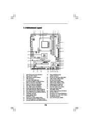
... AUDIO CODEC Super I/O CD1 1 HD_AUDIO1 LPT1 1 PCIE1 AMD 880G Chipset Hybrid CrossFire PCIE2 880GM-LE FX PWR_FAN1 IDE1 SATAII_4 SATAII_5 SATAII_6 (PORT 3) (PORT 4) (PORT 5) RoHS PCI1 IR1 1 FLOPPY1 PCI2 USB10_11 1 AMD SB710 Chipset SPEAKER1 1 PLED PWRBTN PANEL 1 1 HDLED RESET 8Mb BIOS USB8_9 1 CHA_FAN1 USB6_7 1 SATAII_1 SATAII_2 SATAII_3 (PORT 0) (PORT 1) (PORT 2) 27 26 25 24...
... AUDIO CODEC Super I/O CD1 1 HD_AUDIO1 LPT1 1 PCIE1 AMD 880G Chipset Hybrid CrossFire PCIE2 880GM-LE FX PWR_FAN1 IDE1 SATAII_4 SATAII_5 SATAII_6 (PORT 3) (PORT 4) (PORT 5) RoHS PCI1 IR1 1 FLOPPY1 PCI2 USB10_11 1 AMD SB710 Chipset SPEAKER1 1 PLED PWRBTN PANEL 1 1 HDLED RESET 8Mb BIOS USB8_9 1 CHA_FAN1 USB6_7 1 SATAII_1 SATAII_2 SATAII_3 (PORT 0) (PORT 1) (PORT 2) 27 26 25 24...
User Manual
Page 19
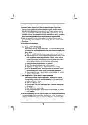
... onto this motherboard. 4. Right-click the display icon and select "Attached", if necessary. F. G. A. If you do not adjust the BIOS setup, the default value of the multi-monitor according to use multiple monitors with your monitors that the value you can adjust the parameters of...[512MB] to enable the function of display icons determines how you would like to the steps below . Click the "Identify" button to enter BIOS setup. C. Click "OK" to positions representing the physical setup of the system memory. Click and drag the display icons to save your system...
... onto this motherboard. 4. Right-click the display icon and select "Attached", if necessary. F. G. A. If you do not adjust the BIOS setup, the default value of the multi-monitor according to use multiple monitors with your monitors that the value you can adjust the parameters of...[512MB] to enable the function of display icons determines how you would like to the steps below . Click the "Identify" button to enter BIOS setup. C. Click "OK" to positions representing the physical setup of the system memory. Click and drag the display icons to save your system...
User Manual
Page 21
... and the discrete graphics card. Please refer to a single display for ATITM Hybrid CrossFireXTM. Step 2. Step 5. For the proper installation procedures, please refer to enter BIOS setup. Enter "Advanced" screen, and enter "Chipset Settings". ATITM Hybrid CrossFireXTM brings multi-GPU performance capabilities by enabling an AMD 880G integrated graphics processor and...
... and the discrete graphics card. Please refer to a single display for ATITM Hybrid CrossFireXTM. Step 2. Step 5. For the proper installation procedures, please refer to enter BIOS setup. Enter "Advanced" screen, and enter "Chipset Settings". ATITM Hybrid CrossFireXTM brings multi-GPU performance capabilities by enabling an AMD 880G integrated graphics processor and...

User Manual
Page 23
... higher standby current provided by power supply. After waiting for 5 seconds. If you need to clear the CMOS when you just finish updating the BIOS, you do not clear the CMOS right after you to short pin2 and pin3 on CLRCMOS1 for 15 seconds, use a jumper cap to clear ...is "Short". To clear and reset the system parameters to enable (see p.12, No. 9) 1_2 2_3 Default Clear CMOS Note: CLRCMOS1 allows you update the BIOS. However, please do the clear-CMOS action. 23 2.7 Jumpers Setup The illustration shows how jumpers are "Short" when jumper cap is placed on these 2 ...
... higher standby current provided by power supply. After waiting for 5 seconds. If you need to clear the CMOS when you just finish updating the BIOS, you do not clear the CMOS right after you to short pin2 and pin3 on CLRCMOS1 for 15 seconds, use a jumper cap to clear ...is "Short". To clear and reset the system parameters to enable (see p.12, No. 9) 1_2 2_3 Default Clear CMOS Note: CLRCMOS1 allows you update the BIOS. However, please do the clear-CMOS action. 23 2.7 Jumpers Setup The illustration shows how jumpers are "Short" when jumper cap is placed on these 2 ...

User Manual
Page 26
... Definition Audio supports Jack Sensing, but the panel wire on the lower right hand taskbar to MIC2_L. Click "Set Default Device" to function correctly. Enter BIOS Setup Utility. G. Front Panel Audio Header (9-pin HD_AUDIO1) (see p.12 No. 16) PLED+ PLEDPWRBTN# GND 1 DUMMY RESET# GND HDLEDHDLED+ This header accommodates several system front...
... Definition Audio supports Jack Sensing, but the panel wire on the lower right hand taskbar to MIC2_L. Click "Set Default Device" to function correctly. Enter BIOS Setup Utility. G. Front Panel Audio Header (9-pin HD_AUDIO1) (see p.12 No. 16) PLED+ PLEDPWRBTN# GND 1 DUMMY RESET# GND HDLEDHDLED+ This header accommodates several system front...
User Manual
Page 33
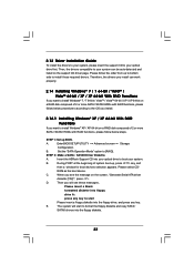
...XP / XP 64-bit on a RAID disk composed of system boot-up, press key, and then a window for boot devices selection appears. Enter BIOS SETUP UTILITY Advanced screen Storage Configuration. Please follow below procedures according to the OS you install. 2.14.1 Installing Windows® XP / XP 64-bit... With RAID Functions If you want to boot your system. Insert the ASRock Support CD into the floppy diskette. 33 D. B. During POST at the beginning of 2 or more SATA / SATAII HDDs with RAID functions, please ...
...XP / XP 64-bit on a RAID disk composed of system boot-up, press key, and then a window for boot devices selection appears. Enter BIOS SETUP UTILITY Advanced screen Storage Configuration. Please follow below procedures according to the OS you install. 2.14.1 Installing Windows® XP / XP 64-bit... With RAID Functions If you want to boot your system. Insert the ASRock Support CD into the floppy diskette. 33 D. B. During POST at the beginning of 2 or more SATA / SATAII HDDs with RAID functions, please ...

User Manual
Page 34
...® XP, or "AMD AHCI Compatible RAID Controller-x64 platform" for proper configuration. Please refer to the BIOS RAID installation guide part of Windows® setup, press F6 to set up BIOS. After step 1, 2, 3, you still need to install a third-party RAID driver. At the beginning of... Installation Guide STEP 3: Install Windows® 7 / 7 64-bit / VistaTM / VistaTM 64-bit OS on your system. 34 A. Before you start to the BIOS RAID installation guide part of 2 or more SATA / SATAII HDDs with RAID functions, please follow below steps. Please refer to install Windows® XP / XP...
...® XP, or "AMD AHCI Compatible RAID Controller-x64 platform" for proper configuration. Please refer to the BIOS RAID installation guide part of Windows® setup, press F6 to set up BIOS. After step 1, 2, 3, you still need to install a third-party RAID driver. At the beginning of... Installation Guide STEP 3: Install Windows® 7 / 7 64-bit / VistaTM / VistaTM 64-bit OS on your system. 34 A. Before you start to the BIOS RAID installation guide part of 2 or more SATA / SATAII HDDs with RAID functions, please follow below steps. Please refer to install Windows® XP / XP...

User Manual
Page 35
... platform" for Windows® XP 64-bit.) 35 When prompted, insert the SATA / SATAII driver diskette containing the AMD AHCI driver. A. Enter BIOS SETUP UTILITY Advanced screen Storage Configuration. At the beginning of Windows® setup, press F6 to install Windows® XP / XP 64-bit on...-bit Without RAID Functions If you still need to set the RAID configuration by using the Windows RAID installation guide in the following path in BIOS first. Select the driver to install according to [RAID] in the Support CD: .. \ RAID Installation Guide NOTE2. Using SATA / SATAII HDDs...
... platform" for Windows® XP 64-bit.) 35 When prompted, insert the SATA / SATAII driver diskette containing the AMD AHCI driver. A. Enter BIOS SETUP UTILITY Advanced screen Storage Configuration. At the beginning of Windows® setup, press F6 to install Windows® XP / XP 64-bit on...-bit Without RAID Functions If you still need to set the RAID configuration by using the Windows RAID installation guide in the following path in BIOS first. Select the driver to install according to [RAID] in the Support CD: .. \ RAID Installation Guide NOTE2. Using SATA / SATAII HDDs...

User Manual
Page 36
... SATA / SATAII HDDs with NCQ and Hot Plug functions (AHCI mode) STEP 1: Set Up BIOS. A. Set the "SATA Operation Mode" option to [IDE]. Enter BIOS SETUP UTILITY Advanced screen Storage Configuration. Enter BIOS SETUP UTILITY Advanced screen Storage Configuration. STEP 2: Install Windows® 7 / 7 64-bit... "SATA Operation Mode" option to [AHCI]. B. Using SATA / SATAII HDDs without NCQ and Hot Plug functions (IDE mode) STEP 1: Set up BIOS. STEP 2: Install Windows® 7 / 7 64-bit / VistaTM / VistaTM 64-bit OS on your SATA / SATAII HDDs without RAID functions,...
... SATA / SATAII HDDs with NCQ and Hot Plug functions (AHCI mode) STEP 1: Set Up BIOS. A. Set the "SATA Operation Mode" option to [IDE]. Enter BIOS SETUP UTILITY Advanced screen Storage Configuration. Enter BIOS SETUP UTILITY Advanced screen Storage Configuration. STEP 2: Install Windows® 7 / 7 64-bit... "SATA Operation Mode" option to [AHCI]. B. Using SATA / SATAII HDDs without NCQ and Hot Plug functions (IDE mode) STEP 1: Set up BIOS. STEP 2: Install Windows® 7 / 7 64-bit / VistaTM / VistaTM 64-bit OS on your SATA / SATAII HDDs without RAID functions,...

User Manual
Page 37
... untied during overclocking, FSB enjoys better margin due to fixed PCI / PCIE buses. Before you enable Untied Overclocking function, please enter "Overclock Mode" option of BIOS setup to set the selection from [Auto] to the warning on page 8 for the possible overclocking risk before you apply Untied Overclocking Technology. 37 2.16...
... untied during overclocking, FSB enjoys better margin due to fixed PCI / PCIE buses. Before you enable Untied Overclocking function, please enter "Overclock Mode" option of BIOS setup to set the selection from [Auto] to the warning on page 8 for the possible overclocking risk before you apply Untied Overclocking Technology. 37 2.16...

User Manual
Page 38
... UTILITY after POST, restart the system by pressing + + , or by turning the system off and then back on the motherboard stores the BIOS SETUP UTILITY. You may not exactly match what you see on the menu bar, and then press to choose among the selections on your system. ... screen has a menu bar with its test routines. You may also restart by pressing the reset button on the system chassis. 3. BIOS SETUP UTILITY 3.1 Introduction This section explains how to use the BIOS SETUP UTILITY to locate and load the Operating System Security To set up the computer. The SPI Memory on .
... UTILITY after POST, restart the system by pressing + + , or by turning the system off and then back on the motherboard stores the BIOS SETUP UTILITY. You may not exactly match what you see on the menu bar, and then press to choose among the selections on your system. ... screen has a menu bar with its test routines. You may also restart by pressing the reset button on the system chassis. 3. BIOS SETUP UTILITY 3.1 Introduction This section explains how to use the BIOS SETUP UTILITY to locate and load the Operating System Security To set up the computer. The SPI Memory on .
User Manual
Page 39
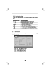
... Tweaker Advanced H/W Monitor System Overview System Time System Date [17:00:09] [Tue 10/18/2011] BIOS Version : 880GM-LE FX P1.0 Processor Type : AMD Phenom(tm) II X3 720 Processor (64bit) Processor Speed : 2800MHz Microcode ... following table for all the settings To save changes and exit the BIOS SETUP UTILITY To jump to the Exit Screen or exit the current screen 3.2 Main Screen When you enter the... BIOS SETUP UTILITY, the Main screen will appear and display the system overview. Navigation Key(s) / ...
... Tweaker Advanced H/W Monitor System Overview System Time System Date [17:00:09] [Tue 10/18/2011] BIOS Version : 880GM-LE FX P1.0 Processor Type : AMD Phenom(tm) II X3 720 Processor (64bit) Processor Speed : 2800MHz Microcode ... following table for all the settings To save changes and exit the BIOS SETUP UTILITY To jump to the Exit Screen or exit the current screen 3.2 Main Screen When you enter the... BIOS SETUP UTILITY, the Main screen will appear and display the system overview. Navigation Key(s) / ...

User Manual
Page 40
BIOS SETUP UTILITY Main OC Tweaker Advanced H/W Monitor Boot Security Exit EZ Overclocking Load Optimized CPU OC Setting Load Optimized mGPU OC Setting CPU Configuration Overclock ...
BIOS SETUP UTILITY Main OC Tweaker Advanced H/W Monitor Boot Security Exit EZ Overclocking Load Optimized CPU OC Setting Load Optimized mGPU OC Setting CPU Configuration Overclock ...

User Manual
Page 41
... Calibration This allows you to enable or disable AMD IO C-State Support. Use this feature. However, it is set to your own risk and expense. BIOS SETUP UTILITY Main OC Tweaker Advanced H/W Monitor Boot Security Exit EZ Overclocking Load Optimized CPU OC Setting Load Optimized mGPU OC Setting CPU Configuration Overclock...
... Calibration This allows you to enable or disable AMD IO C-State Support. Use this feature. However, it is set to your own risk and expense. BIOS SETUP UTILITY Main OC Tweaker Advanced H/W Monitor Boot Security Exit EZ Overclocking Load Optimized CPU OC Setting Load Optimized mGPU OC Setting CPU Configuration Overclock...

User Manual
Page 42
... access contention. 42 Configuration options: [Auto], [x1 200MHz] to enable or disable DDR power down mode. Configuraion options: [Auto], [8 Bit] and [16 Bit]. Memory Timing BIOS SETUP UTILITY OC Tweaker Memory Timing Power Down Enable Bank Interleaving Channel Interleaving CAS Latency (CL) TRCD TRP TRAS Command Rate TRC TRTP TWR TRFC...
... access contention. 42 Configuration options: [Auto], [x1 200MHz] to enable or disable DDR power down mode. Configuraion options: [Auto], [8 Bit] and [16 Bit]. Memory Timing BIOS SETUP UTILITY OC Tweaker Memory Timing Power Down Enable Bank Interleaving Channel Interleaving CAS Latency (CL) TRCD TRP TRAS Command Rate TRC TRTP TWR TRFC...


