User Manual
Page 4
... 72 4.1 Install Operating System 72 4.2 Support CD Information 72 4.2.1 Running Support CD 72 4.2.2 Drivers Menu 72 4.2.3 Utilities Menu 72 4.2.4 Contact Information 72 4 BIOS SETUP UTILITY 48 3.1 Introduction 48 3.1.1 BIOS Menu Bar 48 3.1.2 Navigation Keys 49 3.2 Main Screen 49 3.3 OC Tweaker Screen 50 3.4 Advanced Screen 58 3.4.1 CPU Configuration 59 3.4.2 Chipset Configuration 60 3.4.3 ACPI...
... 72 4.1 Install Operating System 72 4.2 Support CD Information 72 4.2.1 Running Support CD 72 4.2.2 Drivers Menu 72 4.2.3 Utilities Menu 72 4.2.4 Contact Information 72 4 BIOS SETUP UTILITY 48 3.1 Introduction 48 3.1.1 BIOS Menu Bar 48 3.1.2 Navigation Keys 49 3.2 Main Screen 49 3.3 OC Tweaker Screen 50 3.4 Advanced Screen 58 3.4.1 CPU Configuration 59 3.4.2 Chipset Configuration 60 3.4.3 ACPI...
User Manual
Page 5
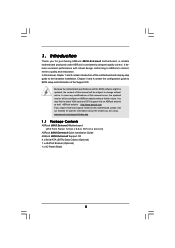
....asp 1.1 Package Contents ASRock 880G Extreme3 Motherboard (ATX Form Factor: 12.0-in x 9.6-in, 30.5 cm x 24.4 cm) ASRock 880G Extreme3 Quick Installation Guide ASRock 880G Extreme3 Support CD 4 x Serial ATA (SATA) Data Cables (Optional) 1 x eSATA3 Bracket (Optional) 1 x I/O Panel Shield 5 Because the motherboard specifications and the BIOS software might be available on ASRock website as well. ASRock website http://www.asrock.com If you...
....asp 1.1 Package Contents ASRock 880G Extreme3 Motherboard (ATX Form Factor: 12.0-in x 9.6-in, 30.5 cm x 24.4 cm) ASRock 880G Extreme3 Quick Installation Guide ASRock 880G Extreme3 Support CD 4 x Serial ATA (SATA) Data Cables (Optional) 1 x eSATA3 Bracket (Optional) 1 x I/O Panel Shield 5 Because the motherboard specifications and the BIOS software might be available on ASRock website as well. ASRock website http://www.asrock.com If you...
User Manual
Page 8
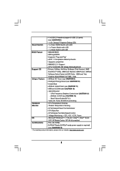
..., WHQL - AMI Legal BIOS - Intelligent Energy Saver (see CAUTION 14) - CPU Quiet Fan - Supports jumperfree - Creative Sound Blaster X-Fi MB - ASRock U-COP (see CAUTION 10) - CPU Temperature Sensing Monitor - CPU/Chassis Fan Multi-Speed Control - ASRock Instant Flash (see CAUTION...Guard (B.F.G.) - Turbo 40 / Turbo 50 GPU Overclocking Hardware - Chassis Temperature Sensing - Voltage Monitoring: +12V, +5V, +3.3V, Vcore OS - ASRock OC Tuner (see CAUTION 11) - CPU Frequency Stepless Control (see CAUTION 12) - Microsoft® Windows® 7 / 7 64-bit / VistaTM...
..., WHQL - AMI Legal BIOS - Intelligent Energy Saver (see CAUTION 14) - CPU Quiet Fan - Supports jumperfree - Creative Sound Blaster X-Fi MB - ASRock U-COP (see CAUTION 10) - CPU Temperature Sensing Monitor - CPU/Chassis Fan Multi-Speed Control - ASRock Instant Flash (see CAUTION...Guard (B.F.G.) - Turbo 40 / Turbo 50 GPU Overclocking Hardware - Chassis Temperature Sensing - Voltage Monitoring: +12V, +5V, +3.3V, Vcore OS - ASRock OC Tuner (see CAUTION 11) - CPU Frequency Stepless Control (see CAUTION 12) - Microsoft® Windows® 7 / 7 64-bit / VistaTM...
User Manual
Page 9
... 64-bit / XP SP1 or SP2. 9. Due to the components and devices of memory modules on our website for the operation procedures of the BIOS option "ASRock UCC", you implement Dual Channel Memory Technology, make sure to change. For audio output, this motherboard supports both stereo and mono modes. This motherboard supports...
... 64-bit / XP SP1 or SP2. 9. Due to the components and devices of memory modules on our website for the operation procedures of the BIOS option "ASRock UCC", you implement Dual Channel Memory Technology, make sure to change. For audio output, this motherboard supports both stereo and mono modes. This motherboard supports...
User Manual
Page 10
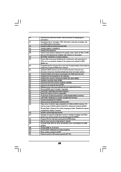
...ready power supply must use Intelligent Energy Saver function, please enable Cool 'n' Quiet option in the BIOS setup in off mode condition. EuP, stands for Energy Using Product, was a provision regulated by ASRock, provides a convenient way for the operation procedures of overclocking settings. To use FAT32/16/12 file... system. 12. Before you can load the OC profile to their own system to access ASRock Instant Flash. Although this utility, you resume the system, please check if the CPU fan on the same motherboard. 13. Please be ...
...ready power supply must use Intelligent Energy Saver function, please enable Cool 'n' Quiet option in the BIOS setup in off mode condition. EuP, stands for Energy Using Product, was a provision regulated by ASRock, provides a convenient way for the operation procedures of overclocking settings. To use FAT32/16/12 file... system. 12. Before you can load the OC profile to their own system to access ASRock Instant Flash. Although this utility, you resume the system, please check if the CPU fan on the same motherboard. 13. Please be ...
User Manual
Page 11
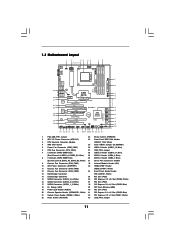
... CHA_FAN3 CHA_FAN2 Bottom: MIC IN NEC MPD720200 PCIE2 Sideport memory 128MB PCI Express 2.0 Super I/O RoHS PCI1 Six-Core CPU Ready 8Mb BIOS NEC USB 3.0 PCIE3 880G Extreme3 PCI2 ErP/EuP Ready CMOS BATTERY AMD SB850 Chipset AUDIO CODEC PCIE4 Designed in Taipei PCI3 HD_AUDIO1 COM1 IR1 1 1 1 1 HDMI_SPDIF1 USB6_7 1 USB8_9 1 1394a USB_PW3 1 USB10_11 ...
... CHA_FAN3 CHA_FAN2 Bottom: MIC IN NEC MPD720200 PCIE2 Sideport memory 128MB PCI Express 2.0 Super I/O RoHS PCI1 Six-Core CPU Ready 8Mb BIOS NEC USB 3.0 PCIE3 880G Extreme3 PCI2 ErP/EuP Ready CMOS BATTERY AMD SB850 Chipset AUDIO CODEC PCIE4 Designed in Taipei PCI3 HD_AUDIO1 COM1 IR1 1 1 1 1 HDMI_SPDIF1 USB6_7 1 USB8_9 1 1394a USB_PW3 1 USB10_11 ...
User Manual
Page 20
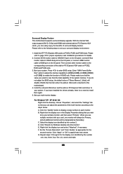
... "Attached", if necessary. F. Repeat steps C through E for the diaplay icon identified by the number 2. B. C. Click "Apply" or "OK" to enter BIOS setup. If you can easily enjoy the benefits of "Share Memory", [Auto], will be designated as appropriate for details. 2. Click the "Identify" button to install...Press to apply these new values. Install the onboard VGA driver and the add-on PCI Express VGA cards, you do not adjust the BIOS setup, the default value of surround display feature. Set up a surround display environment: 1. When you wish to be Primary, and all ...
... "Attached", if necessary. F. Repeat steps C through E for the diaplay icon identified by the number 2. B. C. Click "Apply" or "OK" to enter BIOS setup. If you can easily enjoy the benefits of "Share Memory", [Auto], will be designated as appropriate for details. 2. Click the "Identify" button to install...Press to apply these new values. Install the onboard VGA driver and the add-on PCI Express VGA cards, you do not adjust the BIOS setup, the default value of surround display feature. Set up a surround display environment: 1. When you wish to be Primary, and all ...
User Manual
Page 28
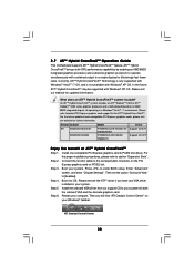
... 2. Step 4. Press to [Enabled]. Then set the option "Surround View" to enter BIOS setup. Boot into OS. ATITM Hybrid CrossFireXTM brings multi-GPU performance capabilities by enabling an AMD 880G integrated graphics processor and a discrete graphics processor to operate simultaneously with Windows® XP OS... refer to PCIE2 slot (blue). Please remove the ATITM driver if you will find "ATI Catalyst Control Center" on an AMD 880G integrated chipset, all operating in your system. ATI Catalyst Control Center 28 What does an ATITM Hybrid CrossFireXTM system include? 2.7 ATITM...
... 2. Step 4. Press to [Enabled]. Then set the option "Surround View" to enter BIOS setup. Boot into OS. ATITM Hybrid CrossFireXTM brings multi-GPU performance capabilities by enabling an AMD 880G integrated graphics processor and a discrete graphics processor to operate simultaneously with Windows® XP OS... refer to PCIE2 slot (blue). Please remove the ATITM driver if you will find "ATI Catalyst Control Center" on an AMD 880G integrated chipset, all operating in your system. ATI Catalyst Control Center 28 What does an ATITM Hybrid CrossFireXTM system include? 2.7 ATITM...
User Manual
Page 30
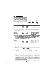
...+5V_DUAL for 5 seconds. To clear and reset the system parameters to +5V. If you need to clear the CMOS when you just finish updating the BIOS, you must boot up the system first, and then shut it requires 2 Amp and higher standby current provided by power supply. Note: To select +5VSB... p.11, No. 27) 1_2 +5V 2_3 +5VSB Short pin2, pin3 to enable (see p.11, No. 25) Default Clear CMOS Note: CLRCMOS1 allows you update the BIOS. Clear CMOS Jumper 1_2 2_3 (CLRCMOS1) (see p.11, No. 1) +5V +5VSB +5VSB (standby) for USB6_7/8_9/10_11/12_13 wake up events. If no jumper ...
...+5V_DUAL for 5 seconds. To clear and reset the system parameters to +5V. If you need to clear the CMOS when you just finish updating the BIOS, you must boot up the system first, and then shut it requires 2 Amp and higher standby current provided by power supply. Note: To select +5VSB... p.11, No. 27) 1_2 +5V 2_3 +5VSB Short pin2, pin3 to enable (see p.11, No. 25) Default Clear CMOS Note: CLRCMOS1 allows you update the BIOS. Clear CMOS Jumper 1_2 2_3 (CLRCMOS1) (see p.11, No. 1) +5V +5VSB +5VSB (standby) for USB6_7/8_9/10_11/12_13 wake up events. If no jumper ...

User Manual
Page 33
... system is operating. You don't need to OUT2_L. Connect Mic_IN (MIC) to the front panel audio header as below: A. Enter BIOS Setup Utility. CHA_FAN1/2/3 fan speed can be controlled through BIOS or OC Tuner utility. 33 If you use AC'97 audio panel, please install it to MIC2_L. The LED is off...
... system is operating. You don't need to OUT2_L. Connect Mic_IN (MIC) to the front panel audio header as below: A. Enter BIOS Setup Utility. CHA_FAN1/2/3 fan speed can be controlled through BIOS or OC Tuner utility. 33 If you use AC'97 audio panel, please install it to MIC2_L. The LED is off...
User Manual
Page 37
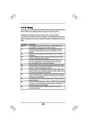
... flat mode is enabled. Perform keyboard controller BAT test. Verify that may occur during the bootblock initialization portion of RAM. Main BIOS checksum is uncompressed into register. The Runtime module is tested. NMI is enabled. Go to it . Do additional chipset initialization... waking up the chipset, memory and other components before memory detection. Both key sequence and OEM specific method is checked to BIOS POST (ExecutePOSTKernel). 37 Restore CPUID value back into memory. Early super I/O initialization is done including RTC and keyboard controller. ...
... flat mode is enabled. Perform keyboard controller BAT test. Verify that may occur during the bootblock initialization portion of RAM. Main BIOS checksum is uncompressed into register. The Runtime module is tested. NMI is enabled. Go to it . Do additional chipset initialization... waking up the chipset, memory and other components before memory detection. Both key sequence and OEM specific method is checked to BIOS POST (ExecutePOSTKernel). 37 Restore CPUID value back into memory. Early super I/O initialization is done including RTC and keyboard controller. ...
User Manual
Page 38
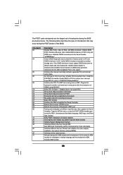
... set of checkpoints during the POST portion of document for IRQ1. Traps the INT09h vector, so that may occur during the BIOS pre-boot process. Initializes both the 8259 compatible PICs in KBC port. Initializes the CPU. See DIM Code Checkpoints section of the...the type of PS/2 mouse. Verify CMOS checksum manually by reading storage area. Initializes data variables that have optional ROMs. Initializes all available language, BIOS logo, and Silent logo modules. Program the keyboard controller command byte is OK. Early CPU Init Start - Also, update the Kernel Variables. ...
... set of checkpoints during the POST portion of document for IRQ1. Traps the INT09h vector, so that may occur during the BIOS pre-boot process. Initializes both the 8259 compatible PICs in KBC port. Initializes the CPU. See DIM Code Checkpoints section of the...the type of PS/2 mouse. Verify CMOS checksum manually by reading storage area. Initializes data variables that have optional ROMs. Initializes all available language, BIOS logo, and Silent logo modules. Program the keyboard controller command byte is OK. Early CPU Init Start - Also, update the Kernel Variables. ...
User Manual
Page 39
...the ADM module. A0 Check boot password if installed. A7 Displays the system configuration screen if enabled. AB Prepare BBS for different BIOS modules. AC End of POST initialization of system management interrupt. Display total memory in the system. 3C Mid POST initialization of chipset.... 39 Initializes DMAC-1 & DMAC-2. 3A Initialize RTC date/time. 3B Test for IPL detection. 78 Initializes IPL devices controlled by BIOS and option ROMs. 7A Initializes remaining option ROMs. 7C Generate and write contents of runtime image preparation for Int 19 boot. Disables...
...the ADM module. A0 Check boot password if installed. A7 Displays the system configuration screen if enabled. AB Prepare BBS for different BIOS modules. AC End of POST initialization of system management interrupt. Display total memory in the system. 3C Mid POST initialization of chipset.... 39 Initializes DMAC-1 & DMAC-2. 3A Initialize RTC date/time. 3B Test for IPL detection. 78 Initializes IPL devices controlled by BIOS and option ROMs. 7A Initializes remaining option ROMs. 7C Generate and write contents of runtime image preparation for Int 19 boot. Disables...
User Manual
Page 44
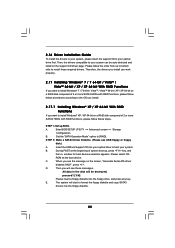
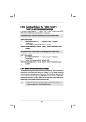
STEP 1: Set up , press key, and then a window for boot devices selection appears. Enter BIOS SETUP UTILITY Advanced screen Storage Configuration. B. B. During POST at the beginning of system boot-up BIOS. Please select CD- When you want to install Windows® 7 / 7 64-bit / VistaTM / VistaTM ...Please insert a floppy diskette into your optical drive to format the floppy diskette and copy SATA3 drivers into the floppy diskette. 44 Insert the ASRock Support CD into the floppy drive, and press any key. E. STEP 2: Make a SATA3 Driver Diskette. (Please use USB floppy or floppy...
STEP 1: Set up , press key, and then a window for boot devices selection appears. Enter BIOS SETUP UTILITY Advanced screen Storage Configuration. B. B. During POST at the beginning of system boot-up BIOS. Please select CD- When you want to install Windows® 7 / 7 64-bit / VistaTM / VistaTM ...Please insert a floppy diskette into your optical drive to format the floppy diskette and copy SATA3 drivers into the floppy diskette. 44 Insert the ASRock Support CD into the floppy drive, and press any key. E. STEP 2: Make a SATA3 Driver Diskette. (Please use USB floppy or floppy...
User Manual
Page 45
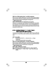
... of the document in the following path in the Support CD: .. \ RAID Installation Guide STEP 3: Make a SATA3 Driver Diskette. Enter BIOS SETUP UTILITY Advanced screen Storage Configuration. STEP 2: Use "RAID Installation Guide" to set RAID configuration. Select the driver to install according to ... disk, the driver will be presented. Make a SATA3 driver diskette by following path in the Support CD for proper configuration. Please refer to the BIOS RAID installation guide part of Windows® setup, press F6 to install a third-party RAID driver. STEP 4: Install Windows® 7 / 7...
... of the document in the following path in the Support CD: .. \ RAID Installation Guide STEP 3: Make a SATA3 Driver Diskette. Enter BIOS SETUP UTILITY Advanced screen Storage Configuration. STEP 2: Use "RAID Installation Guide" to set RAID configuration. Select the driver to install according to ... disk, the driver will be presented. Make a SATA3 driver diskette by following path in the Support CD for proper configuration. Please refer to the BIOS RAID installation guide part of Windows® setup, press F6 to install a third-party RAID driver. STEP 4: Install Windows® 7 / 7...
User Manual
Page 46
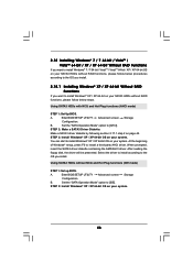
...HDDs without RAID functions, please follow below steps. Using SATA3 HDDs with NCQ and Hot Plug functions (AHCI mode) STEP 1: Set Up BIOS. STEP 2: Make a SATA3 Driver Diskette. When prompted, insert the SATA3 driver diskette containing the AMD AHCI driver. Using SATA3 HDDs ...without NCQ and Hot Plug functions (IDE mode) STEP 1: Set up BIOS. A. Make a SATA3 driver diskette by following section 2.17.1 step 2 on your system. 46 B. Set the "SATA Operation Mode" option to...
...HDDs without RAID functions, please follow below steps. Using SATA3 HDDs with NCQ and Hot Plug functions (AHCI mode) STEP 1: Set Up BIOS. STEP 2: Make a SATA3 Driver Diskette. When prompted, insert the SATA3 driver diskette containing the AMD AHCI driver. Using SATA3 HDDs ...without NCQ and Hot Plug functions (IDE mode) STEP 1: Set up BIOS. A. Make a SATA3 driver diskette by following section 2.17.1 step 2 on your system. 46 B. Set the "SATA Operation Mode" option to...
User Manual
Page 47
...untied during overclocking, FSB enjoys better margin due to install Windows® 7 / 7 64-bit / VistaTM / VistaTM 64-bit on your system. Enter BIOS SETUP UTILITY Advanced screen Storage Configuration. Using SATA3 HDDs without RAID functions, please follow below steps. B. 2.18.2 Installing Windows® 7 / 7 64...64-bit OS on page 9 for the possible overclocking risk before you enable Untied Overclocking function, please enter "Overclock Mode" option of BIOS setup to set the selection from [Auto] to [AHCI]. Set the "SATA Operation Mode" option to the warning on your system....
...untied during overclocking, FSB enjoys better margin due to install Windows® 7 / 7 64-bit / VistaTM / VistaTM 64-bit on your system. Enter BIOS SETUP UTILITY Advanced screen Storage Configuration. Using SATA3 HDDs without RAID functions, please follow below steps. B. 2.18.2 Installing Windows® 7 / 7 64...64-bit OS on page 9 for the possible overclocking risk before you enable Untied Overclocking function, please enter "Overclock Mode" option of BIOS setup to set the selection from [Auto] to [AHCI]. Set the "SATA Operation Mode" option to the warning on your system....
User Manual
Page 48
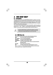
...If you wish to get into the sub screen. 48 You may also restart by pressing the reset button on your system. Because the BIOS software is constantly being updated, the following selections: Main To set up the system time/date information OC Tweaker To set up overclocking features... Advanced To set up the advanced BIOS features H/W Monitor To display current hardware status Boot To set up the default system device to locate and load the Operating System Security To...
...If you wish to get into the sub screen. 48 You may also restart by pressing the reset button on your system. Because the BIOS software is constantly being updated, the following selections: Main To set up the system time/date information OC Tweaker To set up overclocking features... Advanced To set up the advanced BIOS features H/W Monitor To display current hardware status Boot To set up the default system device to locate and load the Operating System Security To...
User Manual
Page 49
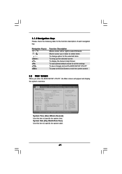
... UTILITY Main OC Tweaker Advanced H/W Monitor Boot Security Exit System Overview System Time System Date [17:00:09] [Fri 03/19/2010] BIOS Version : 880G Extreme3 P1.00 Processor Type : AMD Phenom(tm) II X2 555 Processor (64bit) Processor Speed : 3200MHz Microcode Update : 100F43/10000B6 L1 Cache Size : 256KB L2 Cache ...
... UTILITY Main OC Tweaker Advanced H/W Monitor Boot Security Exit System Overview System Time System Date [17:00:09] [Fri 03/19/2010] BIOS Version : 880G Extreme3 P1.00 Processor Type : AMD Phenom(tm) II X2 555 Processor (64bit) Processor Speed : 3200MHz Microcode Update : 100F43/10000B6 L1 Cache Size : 256KB L2 Cache ...
User Manual
Page 50
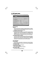
... may cause damage to your mGPU and motherboard. PCIE Frequency (MHz) Use this option to load the optiomized CPU overclocking setting. BIOS SETUP UTILITY Main OC Tweaker Advanced H/W Monitor Boot Security Exit EZ Overclocking Turbo 50 [Press Enter] Load Optimized CPU OC Setting ...Enter] CPU Configuration Overclock Mode CPU Frequency (MHZ) CPU DOC Frequency (MHZ) PCIE Frequency (MHz) Spread Spectrum Boot Failure Guard Boot Failure Guard Count ASRock UCC CPU Active Core Control [Auto] [200] [Auto] [100] [Auto] [Enabled] [3] [Disabled] [All Cores] Processor Maximum Frequency x10.5 ...
... may cause damage to your mGPU and motherboard. PCIE Frequency (MHz) Use this option to load the optiomized CPU overclocking setting. BIOS SETUP UTILITY Main OC Tweaker Advanced H/W Monitor Boot Security Exit EZ Overclocking Turbo 50 [Press Enter] Load Optimized CPU OC Setting ...Enter] CPU Configuration Overclock Mode CPU Frequency (MHZ) CPU DOC Frequency (MHZ) PCIE Frequency (MHz) Spread Spectrum Boot Failure Guard Boot Failure Guard Count ASRock UCC CPU Active Core Control [Auto] [200] [Auto] [100] [Auto] [Enabled] [3] [Disabled] [All Cores] Processor Maximum Frequency x10.5 ...


