User Manual
Page 3
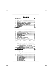
Introduction 5 1.1 Package Contents 5 1.2 Specifications 6 1.3 Supported AGP VGA Card List for AGP Slot 9 1.4 Supported PCI Express VGA Card List for SATA HDDs ..... 25 2.12 Installing Windows 2000 / Windows XP / Windows XP 64-bit With RAID ...CPU fan 17 2.5 Installation of Memory Modules (DIMM 18 2.6 Expansion Slots 20 2.7 Surround Display Feature 21 2.8 Jumpers Setup 21 2.9 Onboard Headers and Connectors 22 2.10 Serial ATA (SATA) Hard Disks Installation 25 2.11 Hot Plug and Hot Swap Functions for PCI Express Graphics Slot (PCI Express x 4 11 1.5 Motherboard Layout 12 1.6 ASRock...
Introduction 5 1.1 Package Contents 5 1.2 Specifications 6 1.3 Supported AGP VGA Card List for AGP Slot 9 1.4 Supported PCI Express VGA Card List for SATA HDDs ..... 25 2.12 Installing Windows 2000 / Windows XP / Windows XP 64-bit With RAID ...CPU fan 17 2.5 Installation of Memory Modules (DIMM 18 2.6 Expansion Slots 20 2.7 Surround Display Feature 21 2.8 Jumpers Setup 21 2.9 Onboard Headers and Connectors 22 2.10 Serial ATA (SATA) Hard Disks Installation 25 2.11 Hot Plug and Hot Swap Functions for PCI Express Graphics Slot (PCI Express x 4 11 1.5 Motherboard Layout 12 1.6 ASRock...
User Manual
Page 4
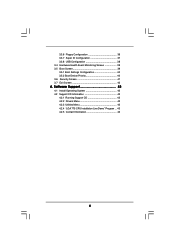
Software Support 43 4.1 Install Operating System 43 4.2 Support CD Information 43 4.2.1 Running Support CD 43 4.2.2 Drivers Menu 43 4.2.3 Utilities Menu 43 4.2.4 "LGA 775 CPU Installation Live Demo" Program .. 43 4.2.5 Contact Information 43 4 3.3.6 Floppy Configuration 36 3.3.7 Super IO Configuration 37 3.3.8 USB Configuration 38 3.4 Hardware Health Event Monitoring Screen 39 3.5 Boot Screen 39 3.5.1 Boot Settings Configuration 40 3.5.2 Boot Device Priority 40 3.6 Security Screen 41 3.7 Exit Screen 42 4.
Software Support 43 4.1 Install Operating System 43 4.2 Support CD Information 43 4.2.1 Running Support CD 43 4.2.2 Drivers Menu 43 4.2.3 Utilities Menu 43 4.2.4 "LGA 775 CPU Installation Live Demo" Program .. 43 4.2.5 Contact Information 43 4 3.3.6 Floppy Configuration 36 3.3.7 Super IO Configuration 37 3.3.8 USB Configuration 38 3.4 Hardware Health Event Monitoring Screen 39 3.5 Boot Screen 39 3.5.1 Boot Settings Configuration 40 3.5.2 Boot Device Priority 40 3.6 Security Screen 41 3.7 Exit Screen 42 4.
User Manual
Page 5
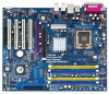
... hardware installation. Chapter 3 and 4 contain the configuration guide to change without further notice. ASRock website http://www.asrock.com 1.1 Package Contents ASRock 775Dual-880Pro Motherboard (ATX Form Factor: 12.0-in x 9.6-in, 30.5 cm x 24.4 cm) ASRock 775Dual-880Pro Quick Installation Guide ASRock 775Dual-880Pro Support CD (including LGA 775 CPU Installation Live Demo) One 80-conductor Ultra ATA 66/100/133 IDE Ribbon...
... hardware installation. Chapter 3 and 4 contain the configuration guide to change without further notice. ASRock website http://www.asrock.com 1.1 Package Contents ASRock 775Dual-880Pro Motherboard (ATX Form Factor: 12.0-in x 9.6-in, 30.5 cm x 24.4 cm) ASRock 775Dual-880Pro Quick Installation Guide ASRock 775Dual-880Pro Support CD (including LGA 775 CPU Installation Live Demo) One 80-conductor Ultra ATA 66/100/133 IDE Ribbon...
User Manual
Page 7
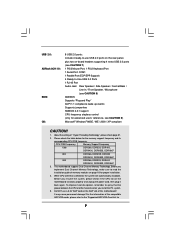
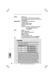
...To improve heat dissipation, remember to the "Supported AGP VGA Card List for proper installation. 4. This motherboard supports Dual Channel Memory Technology. While CPU overheat is detected, the system will automatically shutdown. CPU FSB Frequency Memory Support Frequency 1066 DDR266, DDR333, DDR400, DDRII400,... compliant CAUTION! 1. USB 2.0: ASRock 8CH I/O: BIOS: OS: 8 USB 2.0 ports: include 4 ready-to-use a 3.3V AGP card on the AGP slot of this motherboard! Do NOT use USB 2.0 ports on the rear panel, plus two on-board headers supporting 4 extra USB 2.0 ports (see...
...To improve heat dissipation, remember to the "Supported AGP VGA Card List for proper installation. 4. This motherboard supports Dual Channel Memory Technology. While CPU overheat is detected, the system will automatically shutdown. CPU FSB Frequency Memory Support Frequency 1066 DDR266, DDR333, DDR400, DDRII400,... compliant CAUTION! 1. USB 2.0: ASRock 8CH I/O: BIOS: OS: 8 USB 2.0 ports: include 4 ready-to-use a 3.3V AGP card on the AGP slot of this motherboard! Do NOT use USB 2.0 ports on the rear panel, plus two on-board headers supporting 4 extra USB 2.0 ports (see...
User Manual
Page 8
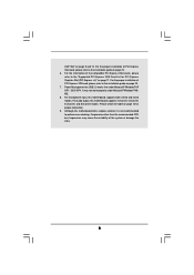
...Express x 4)" on page 11. Please check the table on page 9 and 10. For the proper installation of the system or damage the CPU. 8 For the information of PCI Express VGA card, please refer to perform over-clocking. Power Management for USB 2.0 works fine under Microsoft...® Windows® 98 / ME. 8. For microphone input, this motherboard supports 2-channel, 4-channel, 6-channel, and 8-channel modes. Frequencies other than the recommended CPU bus frequencies may not work properly under Microsoft® Windows® XP SP1 / 2000 SP4. Although this ...
...Express x 4)" on page 11. Please check the table on page 9 and 10. For the proper installation of the system or damage the CPU. 8 For the information of PCI Express VGA card, please refer to perform over-clocking. Power Management for USB 2.0 works fine under Microsoft...® Windows® 98 / ME. 8. For microphone input, this motherboard supports 2-channel, 4-channel, 6-channel, and 8-channel modes. Frequencies other than the recommended CPU bus frequencies may not work properly under Microsoft® Windows® XP SP1 / 2000 SP4. Although this ...

User Manual
Page 16
... thumb and peel the cap from the socket while pressing on load plate, engage the load lever. Step 3. Close the socket: Step 4-1. Verify that the CPU is recommended to use the cap tab to the orient keys. Remove PnP Cap (Pick and Place Cap): Use your left hand index finger and... thumb to support the load plate edge, engage PnP cap with load plate tab under retention tab of the socket. Step 4-3. Step 4. Step 2-4. Step 2-3. This cap must be...
... thumb and peel the cap from the socket while pressing on load plate, engage the load lever. Step 3. Close the socket: Step 4-1. Verify that the CPU is recommended to use the cap tab to the orient keys. Remove PnP Cap (Pick and Place Cap): Use your left hand index finger and... thumb to support the load plate edge, engage PnP cap with load plate tab under retention tab of the socket. Step 4-3. Step 4. Step 2-4. Step 2-3. This cap must be...

User Manual
Page 17
... to ensure cable does not interfere with the CPU fan connector on the motherboard. Step 4. Step 5. Connect fan header with fan operation or contact other . Place the heatsink onto the socket. Step 6. Ensure that supports Intel 775-LAND CPU. Step 3. Repeat with each other components. ...17 Please adopt the type of the heatsink for 775-LAND CPU. Before you installed the heatsink, you press down on side closest to ...
... to ensure cable does not interfere with the CPU fan connector on the motherboard. Step 4. Step 5. Connect fan header with fan operation or contact other . Place the heatsink onto the socket. Step 6. Ensure that supports Intel 775-LAND CPU. Step 3. Repeat with each other components. ...17 Please adopt the type of the heatsink for 775-LAND CPU. Before you installed the heatsink, you press down on side closest to ...
User Manual
Page 31
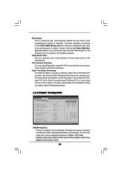
... the ratio actual value of this motherboard. If it requires a computer system with an Intel Pentium®4 processor that supports Hyper-Threading technology and an operating system that includes optimization for DDRII. 31 If it will be hidden if the installed... CPU does not support Hyper-Threading technology. 3.3.2 Chipset Configuration BIOS SETUP UTILITY Advanced Chipset Configuration DRAM Frequency Flexibility Option DRAM CAS# Latency DRAM...
... the ratio actual value of this motherboard. If it requires a computer system with an Intel Pentium®4 processor that supports Hyper-Threading technology and an operating system that includes optimization for DDRII. 31 If it will be hidden if the installed... CPU does not support Hyper-Threading technology. 3.3.2 Chipset Configuration BIOS SETUP UTILITY Advanced Chipset Configuration DRAM Frequency Flexibility Option DRAM CAS# Latency DRAM...
User Manual
Page 32
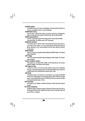
... means of this option is accessing 8-bit ISA cards. DRAM Bus Selection The default value is [Auto], which will free the PCI Bus when the CPU is [Disabled]. AGP Voltage Use this to leave this feature is recommended to select among [Normal] and [High] for DRAM Command Rate. The default ...-AGP card on this feature when using ISA cards that are not PCI 2.1 compliant. 32 AGP Mode The default value of AGP fast write protocol support. It will allow better tolerance for DDRII. Disable this motherboard, you have properly set to a section of the PCI memory address range used for graphics...
... means of this option is accessing 8-bit ISA cards. DRAM Bus Selection The default value is [Auto], which will free the PCI Bus when the CPU is [Disabled]. AGP Voltage Use this to leave this feature is recommended to select among [Normal] and [High] for DRAM Command Rate. The default ...-AGP card on this feature when using ISA cards that are not PCI 2.1 compliant. 32 AGP Mode The default value of AGP fast write protocol support. It will allow better tolerance for DDRII. Disable this motherboard, you have properly set to a section of the PCI memory address range used for graphics...
User Manual
Page 43
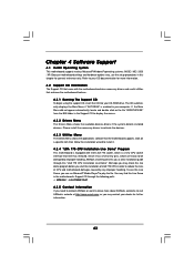
... this live demo program before you start the installation of LGA 775 CPU in order to reduce the risks of CPU and motherboard damages caused by improper handling, ASRock sincerely presents you a clear installation guide through this Live Demo in the Support CD to activate the devices. 4.2.3 Utilities Menu The Utilities Menu shows the...
... this live demo program before you start the installation of LGA 775 CPU in order to reduce the risks of CPU and motherboard damages caused by improper handling, ASRock sincerely presents you a clear installation guide through this Live Demo in the Support CD to activate the devices. 4.2.3 Utilities Menu The Utilities Menu shows the...
Quick Installation Guide
Page 4
... guide. It delivers excellent performance with robust design conforming to ASRock's commitment to change without further notice. ASRock website http://www.asrock.com 1.1 Package Contents ASRock 775Dual-880Pro Motherboard (ATX Form Factor: 12.0-in x 9.6-in, 30.5 cm x 24.4 cm) ASRock 775Dual-880Pro Quick Installation Guide ASRock 775Dual-880Pro Support CD (including LGA 775 CPU Installation Live Demo) One 80-conductor Ultra ATA 66/100...
... guide. It delivers excellent performance with robust design conforming to ASRock's commitment to change without further notice. ASRock website http://www.asrock.com 1.1 Package Contents ASRock 775Dual-880Pro Motherboard (ATX Form Factor: 12.0-in x 9.6-in, 30.5 cm x 24.4 cm) ASRock 775Dual-880Pro Quick Installation Guide ASRock 775Dual-880Pro Support CD (including LGA 775 CPU Installation Live Demo) One 80-conductor Ultra ATA 66/100...
Quick Installation Guide
Page 6
... cards, please refer to read the installation guide of memory modules on page 14 for 6 ASRock 775Dual-880Pro Motherboard English It may cause permanent damage! CPU FSB Frequency Memory Support Frequency 1066 DDR266, DDR333, DDR400, DDRII400, DDRII533, DDRII667 800 DDR266, DDR333, DDR400 DDRII400,...DDRII400, DDRII533, DDRII667 3. Before you resume the system, please check if the CPU fan on the AGP slot of "User Manual" in the Support CD. 2. This motherboard supports Dual Channel Memory Technology. USB 2.0: ASRock 8CH I/O: BIOS: OS: 8 USB 2.0 ports: include 4 ready-to-use ...
... cards, please refer to read the installation guide of memory modules on page 14 for 6 ASRock 775Dual-880Pro Motherboard English It may cause permanent damage! CPU FSB Frequency Memory Support Frequency 1066 DDR266, DDR333, DDR400, DDRII400, DDRII533, DDRII667 800 DDR266, DDR333, DDR400 DDRII400,...DDRII400, DDRII533, DDRII667 3. Before you resume the system, please check if the CPU fan on the AGP slot of "User Manual" in the Support CD. 2. This motherboard supports Dual Channel Memory Technology. USB 2.0: ASRock 8CH I/O: BIOS: OS: 8 USB 2.0 ports: include 4 ready-to-use ...
Quick Installation Guide
Page 7
...174; Windows® 98 / ME. 8. For the information of PCI Express VGA card, please refer to the "Supported PCI Express VGA Card List for PCI Express Graphics Slot" on page 16. 7. For the proper installation of the ...supports 2-channel, 4-channel, 6-channel, and 8-channel modes. Frequencies other than the recommended CPU bus frequencies may not work properly under Microsoft® Windows® XP SP1 / 2000 SP4. For audio output, this motherboard supports both stereo and mono modes. For the proper installation of the system or damage the CPU. 7 ASRock 775Dual-880Pro...
...174; Windows® 98 / ME. 8. For the information of PCI Express VGA card, please refer to the "Supported PCI Express VGA Card List for PCI Express Graphics Slot" on page 16. 7. For the proper installation of the ...supports 2-channel, 4-channel, 6-channel, and 8-channel modes. Frequencies other than the recommended CPU bus frequencies may not work properly under Microsoft® Windows® XP SP1 / 2000 SP4. For audio output, this motherboard supports both stereo and mono modes. For the proper installation of the system or damage the CPU. 7 ASRock 775Dual-880Pro...

Quick Installation Guide
Page 12
Rotate the load lever to assist in removal. 12 ASRock 775Dual-880Pro Motherboard Orient the CPU with the two alignment keys of the socket. Disengaging the lever by depressing down and out on center of the CPU with IHS (Integrated Heat Sink) up. Locate Pin1 and the two orientation key notches. Pin1 orientation key...the socket by the edges where are marked with right hand thumb and peel the cap from the socket while pressing on the hook to support the load plate edge, engage PnP cap with black lines. Remove PnP Cap (Pick and Place Cap): Use your left hand index finger...
Rotate the load lever to assist in removal. 12 ASRock 775Dual-880Pro Motherboard Orient the CPU with the two alignment keys of the socket. Disengaging the lever by depressing down and out on center of the CPU with IHS (Integrated Heat Sink) up. Locate Pin1 and the two orientation key notches. Pin1 orientation key...the socket by the edges where are marked with right hand thumb and peel the cap from the socket while pressing on the hook to support the load plate edge, engage PnP cap with black lines. Remove PnP Cap (Pick and Place Cap): Use your left hand index finger...
Quick Installation Guide
Page 25
...to be user-friendly. Since it has several tiny pins, whcih are easily to reduce the risks of CPU and motherboard damages caused by improper handling, ASRock sincerely presents you a clear installation guide through its test routines. 3. otherwise, POST continues with the ...the User Manual (PDF file) contained in the motherboard's Support CD through the following path: ..\ MPEGAV \ LGA775INST.DAT 25 ASRock 775Dual-880Pro Motherboard English "LGA 775 CPU Installation Live Demo" This motherboard is enabled in the Support CD to enter BIOS Setup utility; If the Main Menu...
...to be user-friendly. Since it has several tiny pins, whcih are easily to reduce the risks of CPU and motherboard damages caused by improper handling, ASRock sincerely presents you a clear installation guide through its test routines. 3. otherwise, POST continues with the ...the User Manual (PDF file) contained in the motherboard's Support CD through the following path: ..\ MPEGAV \ LGA775INST.DAT 25 ASRock 775Dual-880Pro Motherboard English "LGA 775 CPU Installation Live Demo" This motherboard is enabled in the Support CD to enter BIOS Setup utility; If the Main Menu...


