RAID Installation Guide
Page 1
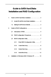
Guide to SATA Hard Disks Installation and RAID Configuration 1. Guide to RAID Configurations 4 2.1 Introduction of Windows 2000 / Windows XP 15 1 Installation of RAID 4 2.2 RAID Configuration Precautions 6 2.3 BIOS Configuration Utility 7 2.3.1 Enter BIOS Configuration Utility 7 2.3.2 Create Disk Array 8 2.3.3 Delete Disk Array 13 2.3.4 Select Boot Array 14 3. Guide to SATA Hard Disks Installation 2 1.1 Serial ATA (SATA) Hard Disks Installation 2 1.2 Making An SATA Driver Diskette 3 2.
Guide to SATA Hard Disks Installation and RAID Configuration 1. Guide to RAID Configurations 4 2.1 Introduction of Windows 2000 / Windows XP 15 1 Installation of RAID 4 2.2 RAID Configuration Precautions 6 2.3 BIOS Configuration Utility 7 2.3.1 Enter BIOS Configuration Utility 7 2.3.2 Create Disk Array 8 2.3.3 Delete Disk Array 13 2.3.4 Select Boot Array 14 3. Guide to SATA Hard Disks Installation 2 1.1 Serial ATA (SATA) Hard Disks Installation 2 1.2 Making An SATA Driver Diskette 3 2.

RAID Installation Guide
Page 3
STEP 1: Insert the ASRock Support CD into your optical drive to boot your system. (Do NOT insert any floppy diskette into the floppy drive at this moment!) STEP 2: During ... driver diskette before you may also set RAID 0 / RAID 1 / JBOD configuration before you install the OS. WARNING! You may start to use "VT8237 SATA RAID BIOS" to set the RAID configuration by using "VIA RAID Tool" in it! 1.2 Making An SATA Driver Diskette If you want to generate Serial ATA driver...
STEP 1: Insert the ASRock Support CD into your optical drive to boot your system. (Do NOT insert any floppy diskette into the floppy drive at this moment!) STEP 2: During ... driver diskette before you may also set RAID 0 / RAID 1 / JBOD configuration before you install the OS. WARNING! You may start to use "VT8237 SATA RAID BIOS" to set the RAID configuration by using "VIA RAID Tool" in it! 1.2 Making An SATA Driver Diskette If you want to generate Serial ATA driver...

RAID Installation Guide
Page 7
2.3 BIOS Configuration Utility 2.3.1 Enter BIOS Configuration Utility After the system powers on, the following information will appear on the screen. The main interface of BIOS configuration utility is as below: 7 Press 'Tab' key to enter BIOS configuration utility.
2.3 BIOS Configuration Utility 2.3.1 Enter BIOS Configuration Utility After the system powers on, the following information will appear on the screen. The main interface of BIOS configuration utility is as below: 7 Press 'Tab' key to enter BIOS configuration utility.

RAID Installation Guide
Page 9
There are two methods to let user select the array drives manually. When using Select Disk Drives method, the channel column will be activated. Select "Select Disk Drives" to create a disk array. When all drives have been selected, press to go back to select the disk drives and create array automatically. Select "Auto Setup" to allow BIOS to the creation steps menu. 9 3. Just highlight the target drives that you want to use and press to select them respectively. One method is "Auto Setup", and another is "Select Disk Drives".
There are two methods to let user select the array drives manually. When using Select Disk Drives method, the channel column will be activated. Select "Select Disk Drives" to create a disk array. When all drives have been selected, press to go back to select the disk drives and create array automatically. Select "Auto Setup" to allow BIOS to the creation steps menu. 9 3. Just highlight the target drives that you want to use and press to select them respectively. One method is "Auto Setup", and another is "Select Disk Drives".
User Manual
Page 3
... UTILITY 28 3.1 Introduction 28 3.1.1 BIOS Menu Bar 28 3.1.2 Navigation Keys 29 3.2 Main Screen 29 3.3 Advanced Screen 30 3.3.1 CPU Configuration 30 3.3.2 Chipset Configuration 31 3.3.3 ACPI Configuration 33 3.3.4 IDE Configuration 34 3.3.5 PCIPnP ... Serial ATA (SATA) Hard Disks Installation 25 2.11 Hot Plug and Hot Swap Functions for PCI Express Graphics Slot (PCI Express x 4 11 1.5 Motherboard Layout 12 1.6 ASRock 8CH I/O 13 2.
... UTILITY 28 3.1 Introduction 28 3.1.1 BIOS Menu Bar 28 3.1.2 Navigation Keys 29 3.2 Main Screen 29 3.3 Advanced Screen 30 3.3.1 CPU Configuration 30 3.3.2 Chipset Configuration 31 3.3.3 ACPI Configuration 33 3.3.4 IDE Configuration 34 3.3.5 PCIPnP ... Serial ATA (SATA) Hard Disks Installation 25 2.11 Hot Plug and Hot Swap Functions for PCI Express Graphics Slot (PCI Express x 4 11 1.5 Motherboard Layout 12 1.6 ASRock 8CH I/O 13 2.
User Manual
Page 5
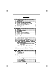
... conforming to ASRock's commitment to BIOS setup and information of this manual occur, the updated version will be updated, the content of the Support CD. You may find the latest memory and CPU support lists on ASRock website without notice. Introduction Thank you for a 3.5-in , 30.5 cm x 24.4 cm) ASRock 775Dual-880Pro Quick Installation Guide ASRock 775Dual-880Pro Support...
... conforming to ASRock's commitment to BIOS setup and information of this manual occur, the updated version will be updated, the content of the Support CD. You may find the latest memory and CPU support lists on ASRock website without notice. Introduction Thank you for a 3.5-in , 30.5 cm x 24.4 cm) ASRock 775Dual-880Pro Quick Installation Guide ASRock 775Dual-880Pro Support...
User Manual
Page 7
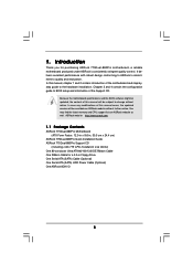
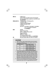
USB 2.0: ASRock 8CH I/O: BIOS: OS: 8 USB 2.0 ports: include 4 ready-to-use a 3.3V AGP card on page 18 for 7 CPU FSB Frequency Memory Support Frequency 1066 DDR266, DDR333, DDR400, DDRII400, ... cause permanent damage! While CPU overheat is detected, the system will automatically shutdown. Please check the table below for advanced users' reference, see CAUTION 8) AMI BIOS Supports "Plug and Play" ACPI 1.1 compliance wake up events Supports jumperfree SMBIOS 2.3.1 support CPU frequency stepless control (only for the memory support frequency and its...
USB 2.0: ASRock 8CH I/O: BIOS: OS: 8 USB 2.0 ports: include 4 ready-to-use a 3.3V AGP card on page 18 for 7 CPU FSB Frequency Memory Support Frequency 1066 DDR266, DDR333, DDR400, DDRII400, ... cause permanent damage! While CPU overheat is detected, the system will automatically shutdown. Please check the table below for advanced users' reference, see CAUTION 8) AMI BIOS Supports "Plug and Play" ACPI 1.1 compliance wake up events Supports jumperfree SMBIOS 2.3.1 support CPU frequency stepless control (only for the memory support frequency and its...
User Manual
Page 21
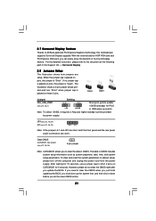
With the external add-on AGP VGA card and PCI Express VGA card, you update the BIOS. Note: To select +5VSB, it down before you to enable (see p.12, No. 1) +5V +5VSB +...Setup The illustration shows how jumpers are setup. If you need to clear the CMOS when you just finish updating the BIOS, you must boot up events. Short Open Jumper Setting PS2_USB_PWR1 1_2 2_3 Short pin2, pin3 to clear the data in... pins, the jumper is "Short". To clear and reset the system parameters to ASRock patented PCI Express Graphics Technology, this motherboard supports Surround Display upgrade.
With the external add-on AGP VGA card and PCI Express VGA card, you update the BIOS. Note: To select +5VSB, it down before you to enable (see p.12, No. 1) +5V +5VSB +...Setup The illustration shows how jumpers are setup. If you need to clear the CMOS when you just finish updating the BIOS, you must boot up events. Short Open Jumper Setting PS2_USB_PWR1 1_2 2_3 Short pin2, pin3 to clear the data in... pins, the jumper is "Short". To clear and reset the system parameters to ASRock patented PCI Express Graphics Technology, this motherboard supports Surround Display upgrade.
User Manual
Page 26
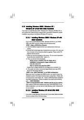
Insert the ASRock Support CD into the floppy diskette. C. The system will lose ALL data ...your SATA HDDs with RAID functions, please follow the below steps. 26 During POST at the following path: .. \ SATA RAID BIOS STEP 3: Install Windows 2000 / Windows XP OS on your system. Then you want to generate Serial ATA driver diskette [YN]?", ...below steps. After making a SATA driver diskette and using "SATA RAID BIOS" to set RAID configuration. Please select CDROM as the boot device. E. STEP 2: Use "SATA RAID BIOS" to format and copy files [YN]? Start to set RAID configuration,...
Insert the ASRock Support CD into the floppy diskette. C. The system will lose ALL data ...your SATA HDDs with RAID functions, please follow the below steps. 26 During POST at the following path: .. \ SATA RAID BIOS STEP 3: Install Windows 2000 / Windows XP OS on your system. Then you want to generate Serial ATA driver diskette [YN]?", ...below steps. After making a SATA driver diskette and using "SATA RAID BIOS" to set RAID configuration. Please select CDROM as the boot device. E. STEP 2: Use "SATA RAID BIOS" to format and copy files [YN]? Start to set RAID configuration,...
User Manual
Page 27
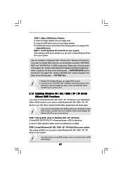
... set up RAID functions, there is located in the support CD, "Guide to VIA RAID Tool", which is no need to use both "SATA RAID BIOS" and "VIA RAID Tool" for Windows 2000 / XP / XP 64-bit) A. If you are located at the following path in Windows environment, ...After making a SATA driver diskette, you want to your floppy drive. If you can start to [non-RAID]. After setting up BIOS. Insert the floppy diskette into your floppy diskette. Enter BIOS SETUP UTILITY Advanced screen IDE Configuration. A. Copy the SATA 64-bit drivers to install Windows 98 / ME / 2000 / XP ...
... set up RAID functions, there is located in the support CD, "Guide to VIA RAID Tool", which is no need to use both "SATA RAID BIOS" and "VIA RAID Tool" for Windows 2000 / XP / XP 64-bit) A. If you are located at the following path in Windows environment, ...After making a SATA driver diskette, you want to your floppy drive. If you can start to [non-RAID]. After setting up BIOS. Insert the floppy diskette into your floppy diskette. Enter BIOS SETUP UTILITY Advanced screen IDE Configuration. A. Copy the SATA 64-bit drivers to install Windows 98 / ME / 2000 / XP ...
User Manual
Page 28
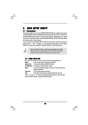
...the system chassis. Please press during the Power-On-Self-Test (POST) to configure your screen. 3.1.1 BIOS Menu Bar The top of the screen has a menu bar with its test routines. You may not...the sub screen. 28 If you see on the motherboard stores the BIOS SETUP UTILITY. The Flash Memory on your system. Because the BIOS software is constantly being updated, the following selections: Main To set... up the system time/date information Advanced To set up the advanced BIOS features H/W Monitor To display current hardware status Boot To set up the default system device...
...the system chassis. Please press during the Power-On-Self-Test (POST) to configure your screen. 3.1.1 BIOS Menu Bar The top of the screen has a menu bar with its test routines. You may not...the sub screen. 28 If you see on the motherboard stores the BIOS SETUP UTILITY. The Flash Memory on your system. Because the BIOS software is constantly being updated, the following selections: Main To set... up the system time/date information Advanced To set up the advanced BIOS features H/W Monitor To display current hardware status Boot To set up the default system device...
User Manual
Page 29
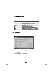
.../Year] Use this item to select a field. 3.1.2 Navigation Keys Please check the following table for all the settings To save changes and exit the BIOS SETUP UTILITY To jump to the Exit Screen or exit the current screen 3.2 Main Screen When you enter the... UTILITY Main Advanced H/W Monitor Boot Security Exit System Overview System Time System Date [17:00:09] [Tue 02/01/2005] BIOS Version : 775Dual-880Pro BIOS P1.00 Processor Type : Intel (R) CPU 3.20 GHz Processor Speed : 3200 MHz Microcode Update : F34/14 Cache Size : 1024KB Total Memory DIMMII 1 DIMM 1 DIMMII 2 DIMM 2 :...
.../Year] Use this item to select a field. 3.1.2 Navigation Keys Please check the following table for all the settings To save changes and exit the BIOS SETUP UTILITY To jump to the Exit Screen or exit the current screen 3.2 Main Screen When you enter the... UTILITY Main Advanced H/W Monitor Boot Security Exit System Overview System Time System Date [17:00:09] [Tue 02/01/2005] BIOS Version : 775Dual-880Pro BIOS P1.00 Processor Type : Intel (R) CPU 3.20 GHz Processor Speed : 3200 MHz Microcode Update : F34/14 Cache Size : 1024KB Total Memory DIMMII 1 DIMM 1 DIMMII 2 DIMM 2 :...
User Manual
Page 30
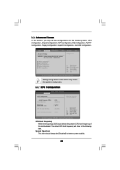
...Configuration, SuperIO Configuration, and USB Configuration. Spread Spectrum This item should always be [Disabled] for the following item. Main BIOS SETUP UTILITY Advanced H/W Monitor Boot Security Exit Advanced Settings WARNING : Setting wrong values in this motherboard. CPU Configuration Chipset ...Select Item Enter Go to malfunction. Setting wrong values in below sections may cause the system to malfunction. 3.3.1 CPU Configuration BIOS SETUP UTILITY Advanced CPU Configuration CPU Host Frequency Actual Frequency (MHz) Spread Spectrum Ratio Status Ratio Actual Value CPU Thermal ...
...Configuration, SuperIO Configuration, and USB Configuration. Spread Spectrum This item should always be [Disabled] for the following item. Main BIOS SETUP UTILITY Advanced H/W Monitor Boot Security Exit Advanced Settings WARNING : Setting wrong values in this motherboard. CPU Configuration Chipset ...Select Item Enter Go to malfunction. Setting wrong values in below sections may cause the system to malfunction. 3.3.1 CPU Configuration BIOS SETUP UTILITY Advanced CPU Configuration CPU Host Frequency Actual Frequency (MHz) Spread Spectrum Ratio Status Ratio Actual Value CPU Thermal ...
User Manual
Page 31
... frequency automatically. Hyper Threading Technology To enable this feature, it will be hidden if the installed CPU does not support Hyper-Threading technology. 3.3.2 Chipset Configuration BIOS SETUP UTILITY Advanced Chipset Configuration DRAM Frequency Flexibility Option DRAM CAS# Latency DRAM Command Rate DRAM Bus Selection [Auto] [Disabled] [Auto] [2T Command] [Auto] DRAM...
... frequency automatically. Hyper Threading Technology To enable this feature, it will be hidden if the installed CPU does not support Hyper-Threading technology. 3.3.2 Chipset Configuration BIOS SETUP UTILITY Advanced Chipset Configuration DRAM Frequency Flexibility Option DRAM CAS# Latency DRAM Command Rate DRAM Bus Selection [Auto] [Disabled] [Auto] [2T Command] [Auto] DRAM...
User Manual
Page 33
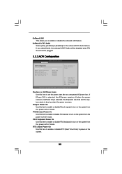
... off mode. OnBoard LAN This allows you select [Auto], the onboard AC'97 Audio will be disabled when PCI Sound card is plugged. 3.3.3 ACPI Configuration BIOS SETUP UTILITY Advanced ACPI Configuration Suspend To RAM Restore on AC / Power Loss Ring-In Power On PCI Devices Power On PS / 2 Keyboard Power On...
... off mode. OnBoard LAN This allows you select [Auto], the onboard AC'97 Audio will be disabled when PCI Sound card is plugged. 3.3.3 ACPI Configuration BIOS SETUP UTILITY Advanced ACPI Configuration Suspend To RAM Restore on AC / Power Loss Ring-In Power On PCI Devices Power On PS / 2 Keyboard Power On...
User Manual
Page 34
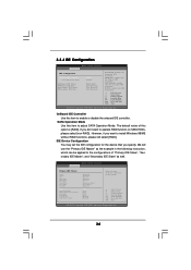
...enable or disable the onboard IDE controller. OnBoard IDE Controller Use this item to the configurations of this option is [RAID]. BIOS SETUP UTILITY Advanced Primary IDE Master Device Vendor Size LBA Mode Block Mode PIO Mode Async DMA Ultra DMA S.M.A.R.T. 3.3.4 IDE Configuration... BIOS SETUP UTILITY Advanced IDE Configuration OnBoard IDE Controller SATA Operation Mode Primary IDE Master Primary IDE Slave Secondary IDE Master Secondary IDE Slave...
...enable or disable the onboard IDE controller. OnBoard IDE Controller Use this item to the configurations of this option is [RAID]. BIOS SETUP UTILITY Advanced Primary IDE Master Device Vendor Size LBA Mode Block Mode PIO Mode Async DMA Ultra DMA S.M.A.R.T. 3.3.4 IDE Configuration... BIOS SETUP UTILITY Advanced IDE Configuration OnBoard IDE Controller SATA Operation Mode Primary IDE Master Primary IDE Slave Secondary IDE Master Secondary IDE Slave...
User Manual
Page 35
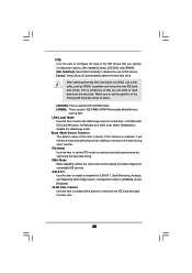
...]. 32-Bit Data Transfer Use this feature is used for a hard disk > 512 MB under DOS and Windows; After selecting the hard disk information into BIOS, use of the Primary IDE hard disk drives to maximize the IDE hard disk data transfer rate. 35
...]. 32-Bit Data Transfer Use this feature is used for a hard disk > 512 MB under DOS and Windows; After selecting the hard disk information into BIOS, use of the Primary IDE hard disk drives to maximize the IDE hard disk data transfer rate. 35
User Manual
Page 36
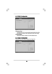
... Latency Timer The default value is recommended to keep the default value unless the installed PCI expansion cards' specifications require other settings. BIOS SETUP UTILITY Advanced Floppy Configuration Floppy A Floppy B [1.44 MB 312"] [Disabled] Select the type of PCI clocks for PCI device ...Item Change Option General Help Load Defaults Save and Exit Exit v02.54 (C) Copyright 1985-2003, American Megatrends, Inc. 3.3.5 PCIPnP Configuration BIOS SETUP UTILITY Advanced PCI / PnP Configuration PCI Latency Timer PCI IDE BusMaster [32] [Enabled] Value in units of floppy drive connected ...
... Latency Timer The default value is recommended to keep the default value unless the installed PCI expansion cards' specifications require other settings. BIOS SETUP UTILITY Advanced Floppy Configuration Floppy A Floppy B [1.44 MB 312"] [Disabled] Select the type of PCI clocks for PCI device ...Item Change Option General Help Load Defaults Save and Exit Exit v02.54 (C) Copyright 1985-2003, American Megatrends, Inc. 3.3.5 PCIPnP Configuration BIOS SETUP UTILITY Advanced PCI / PnP Configuration PCI Latency Timer PCI IDE BusMaster [32] [Enabled] Value in units of floppy drive connected ...
User Manual
Page 37
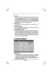
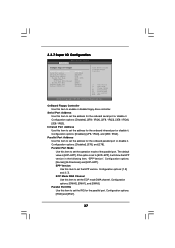
... General Help Load Defaults Save and Exit Exit v02.54 (C) Copyright 1985-2003, American Megatrends, Inc. Configuration options: [IRQ5] and [IRQ7]. 37 3.3.7 Super IO Configuration BIOS SETUP UTILITY Advanced Configure Super IO Chipset OnBoard Floppy Controller Serial Port Address Infrared Port Address Parallel Port Address Parallel Port Mode EPP Version ECP... Mode DMA Channel Parallel Port IRQ OnBoard Game Port OnBoard MIDI Port [Enabled] [3F8 / IRQ4] [Disabled] [378] [ECP + EPP] [1.9] [DMA3] [IRQ7] [Enabled] [Disabled] Allow BIOS to enable or disable floppy drive controller.
... General Help Load Defaults Save and Exit Exit v02.54 (C) Copyright 1985-2003, American Megatrends, Inc. Configuration options: [IRQ5] and [IRQ7]. 37 3.3.7 Super IO Configuration BIOS SETUP UTILITY Advanced Configure Super IO Chipset OnBoard Floppy Controller Serial Port Address Infrared Port Address Parallel Port Address Parallel Port Mode EPP Version ECP... Mode DMA Channel Parallel Port IRQ OnBoard Game Port OnBoard MIDI Port [Enabled] [3F8 / IRQ4] [Disabled] [378] [ECP + EPP] [1.9] [DMA3] [IRQ7] [Enabled] [Disabled] Allow BIOS to enable or disable floppy drive controller.
User Manual
Page 38
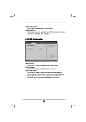
... device connected, "Auto" option will start to select the address for the MIDI Port or disable it . Configuration options: [Disabled], [300], and [330]. 3.3.8 USB Configuration BIOS SETUP UTILITY Advanced USB Configuration USB Controller USB 2.0 Support Legacy USB Support [Enabled] [Enabled] [Disabled] To enable or disable the onboard USB controllers. +F1 F9...
... device connected, "Auto" option will start to select the address for the MIDI Port or disable it . Configuration options: [Disabled], [300], and [330]. 3.3.8 USB Configuration BIOS SETUP UTILITY Advanced USB Configuration USB Controller USB 2.0 Support Legacy USB Support [Enabled] [Enabled] [Disabled] To enable or disable the onboard USB controllers. +F1 F9...


