RAID Installation Guide
Page 2
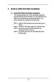
Guide to the SATA hard disk. You may install SATA hard disks on this motherboard for internal storage devices. STEP 1: Install the SATA hard disks into the drive bays of the SATA data cable to the SATA hard disk. 2 STEP 4: ...Connect the other end of your chassis. 1. STEP 2: Connect the SATA power cable to SATA Hard Disks Installation 1.1 Serial ATA (SATA) Hard Disks Installation This motherboard adopts VIA VT8237 southbridge chipset that supports Serial ATA (SATA) hard disks. This section will guide you to the...
Guide to the SATA hard disk. You may install SATA hard disks on this motherboard for internal storage devices. STEP 1: Install the SATA hard disks into the drive bays of the SATA data cable to the SATA hard disk. 2 STEP 4: ...Connect the other end of your chassis. 1. STEP 2: Connect the SATA power cable to SATA Hard Disks Installation 1.1 Serial ATA (SATA) Hard Disks Installation This motherboard adopts VIA VT8237 southbridge chipset that supports Serial ATA (SATA) hard disks. This section will guide you to the...
RAID Installation Guide
Page 4
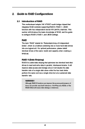
... Striping) RAID 0 is a method combining two or more hard disk drives into one logical unit. For optimal performance, please install identical drives of RAID This motherboard adopts VIA VT8237 south bridge chipset that optimizes two identical hard disk drives to RAID Configurations 2.1 Introduction of the same model and capacity when creating...
... Striping) RAID 0 is a method combining two or more hard disk drives into one logical unit. For optimal performance, please install identical drives of RAID This motherboard adopts VIA VT8237 south bridge chipset that optimizes two identical hard disk drives to RAID Configurations 2.1 Introduction of the same model and capacity when creating...
User Manual
Page 3
... 22 2.10 Serial ATA (SATA) Hard Disks Installation 25 2.11 Hot Plug and Hot Swap Functions for PCI Express Graphics Slot (PCI Express x 4 11 1.5 Motherboard Layout 12 1.6 ASRock 8CH I/O 13 2. BIOS SETUP UTILITY 28 3.1 Introduction 28 3.1.1 BIOS Menu Bar 28 3.1.2 Navigation Keys 29 3.2 Main Screen 29 3.3 Advanced Screen 30 3.3.1 CPU Configuration 30...
... 22 2.10 Serial ATA (SATA) Hard Disks Installation 25 2.11 Hot Plug and Hot Swap Functions for PCI Express Graphics Slot (PCI Express x 4 11 1.5 Motherboard Layout 12 1.6 ASRock 8CH I/O 13 2. BIOS SETUP UTILITY 28 3.1 Introduction 28 3.1.1 BIOS Menu Bar 28 3.1.2 Navigation Keys 29 3.2 Main Screen 29 3.3 Advanced Screen 30 3.3.1 CPU Configuration 30...
User Manual
Page 5
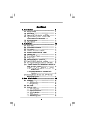
... ASRock website as well. ASRock website http://www.asrock.com 1.1 Package Contents ASRock 775Dual-880Pro Motherboard (ATX Form Factor: 12.0-in x 9.6-in, 30.5 cm x 24.4 cm) ASRock 775Dual-880Pro Quick Installation Guide ASRock 775Dual-880Pro Support CD (including LGA 775 CPU Installation Live Demo) One 80-conductor Ultra ATA 66/100/133 IDE Ribbon Cable One Ribbon Cable for purchasing ASRock 775Dual-880Pro motherboard, a reliable motherboard produced under ASRock...
... ASRock website as well. ASRock website http://www.asrock.com 1.1 Package Contents ASRock 775Dual-880Pro Motherboard (ATX Form Factor: 12.0-in x 9.6-in, 30.5 cm x 24.4 cm) ASRock 775Dual-880Pro Quick Installation Guide ASRock 775Dual-880Pro Support CD (including LGA 775 CPU Installation Live Demo) One 80-conductor Ultra ATA 66/100/133 IDE Ribbon Cable One Ribbon Cable for purchasing ASRock 775Dual-880Pro motherboard, a reliable motherboard produced under ASRock...
User Manual
Page 7
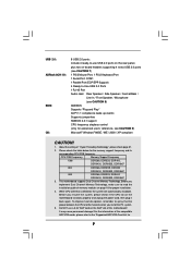
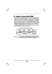
...DDR266, DDR333, DDR400, DDRII400, DDRII533, DDRII667 800 DDR266, DDR333, DDR400 DDRII400, DDRII533, DDRII667 533 DDR266, DDR333, DDR400 DDRII400, DDRII533, DDRII667 3. USB 2.0: ASRock 8CH I/O: BIOS: OS: 8 USB 2.0 ports: include 4 ready-to-use a 3.3V AGP card on -board headers supporting 4 extra USB 2.0 ports (... advanced users' reference, see CAUTION 9) Microsoft® Windows® 98SE / ME / 2000 / XP compliant CAUTION! 1. This motherboard supports Dual Channel Memory Technology. To improve heat dissipation, remember to the "Supported AGP VGA Card List for 7 About the setting ...
...DDR266, DDR333, DDR400, DDRII400, DDRII533, DDRII667 800 DDR266, DDR333, DDR400 DDRII400, DDRII533, DDRII667 533 DDR266, DDR333, DDR400 DDRII400, DDRII533, DDRII667 3. USB 2.0: ASRock 8CH I/O: BIOS: OS: 8 USB 2.0 ports: include 4 ready-to-use a 3.3V AGP card on -board headers supporting 4 extra USB 2.0 ports (... advanced users' reference, see CAUTION 9) Microsoft® Windows® 98SE / ME / 2000 / XP compliant CAUTION! 1. This motherboard supports Dual Channel Memory Technology. To improve heat dissipation, remember to the "Supported AGP VGA Card List for 7 About the setting ...
User Manual
Page 8
...works fine under Microsoft® Windows® 98 / ME. 8. Please check the table on page 20. 6. For audio output, this motherboard offers stepless control, it is not recommended to the installation guide on page 9 and 10. Power Management for proper connection. 9. Frequencies other...not work properly under Microsoft® Windows® XP SP1 / 2000 SP4. Although this motherboard supports 2-channel, 4-channel, 6-channel, and 8-channel modes. For microphone input, this motherboard supports both stereo and mono modes. For the proper installation of PCI Express VGA card, ...
...works fine under Microsoft® Windows® 98 / ME. 8. Please check the table on page 20. 6. For audio output, this motherboard offers stepless control, it is not recommended to the installation guide on page 9 and 10. Power Management for proper connection. 9. Frequencies other...not work properly under Microsoft® Windows® XP SP1 / 2000 SP4. Although this motherboard supports 2-channel, 4-channel, 6-channel, and 8-channel modes. For microphone input, this motherboard supports both stereo and mono modes. For the proper installation of PCI Express VGA card, ...
User Manual
Page 14
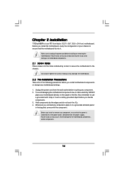
... NEVER place your chassis to unplug the power cord before installing or removing the motherboard. Failure to do so may damage the motherboard. 2.2 Pre-installation Precautions Take note of your motherboard directly on a grounded antistatic pad or in the bag that the power is ... that the motherboard fits into the holes indicated by the edges and do not touch the ICs. 4. Unplug the power cord from the power supply. Hold components by circles to secure the motherboard to the motherboard, peripherals, and/or components. 14 Chapter 2 Installation 775Dual-880Pro is detached ...
... NEVER place your chassis to unplug the power cord before installing or removing the motherboard. Failure to do so may damage the motherboard. 2.2 Pre-installation Precautions Take note of your motherboard directly on a grounded antistatic pad or in the bag that the power is ... that the motherboard fits into the holes indicated by the edges and do not touch the ICs. 4. Unplug the power cord from the power supply. Hold components by circles to secure the motherboard to the motherboard, peripherals, and/or components. 14 Chapter 2 Installation 775Dual-880Pro is detached ...

User Manual
Page 16
Verify that the CPU is recommended to use the cap tab to the orient keys. This cap must be placed if returning the motherboard for after service. Rotate the load plate onto the IHS. Secure load lever with the two alignment keys of the socket. Step 2-3. Step 3. Step 4-2. Carefully ...
Verify that the CPU is recommended to use the cap tab to the orient keys. This cap must be placed if returning the motherboard for after service. Rotate the load plate onto the IHS. Secure load lever with the two alignment keys of the socket. Step 2-3. Step 3. Step 4-2. Carefully ...

User Manual
Page 17
.... Step 1. Ensure fan cables are securely fastened and in good contact with the CPU fan connector on fastener caps with the motherboard throughholes. Align fasteners with thumb to ensure cable does not interfere with remaining fasteners. Rotate the fastener clockwise, then press down ...the fasteners without rotating them clockwise, the heatsink cannot be secured on the motherboard (CPU_FAN1, see page 12, No. 5). Repeat with fan operation or contact other . Secure excess cable with tie-wrap to install...
.... Step 1. Ensure fan cables are securely fastened and in good contact with the CPU fan connector on fastener caps with the motherboard throughholes. Align fasteners with thumb to ensure cable does not interfere with remaining fasteners. Rotate the fastener clockwise, then press down ...the fasteners without rotating them clockwise, the heatsink cannot be secured on the motherboard (CPU_FAN1, see page 12, No. 5). Repeat with fan operation or contact other . Secure excess cable with tie-wrap to install...
User Manual
Page 18
... channel configuration, you have to install identical (the same brand, speed, size and chip-type) DDR DIMM pair in the slots of Memory Modules (DIMM) 775Dual-880Pro motherboard provides two 184-pin DDR (Double Data Rate) DIMM slots and two 240-pin DDRII DIMM slots, and supports Dual Channel Memory Technology. Yellow slots...
... channel configuration, you have to install identical (the same brand, speed, size and chip-type) DDR DIMM pair in the slots of Memory Modules (DIMM) 775Dual-880Pro motherboard provides two 184-pin DDR (Double Data Rate) DIMM slots and two 240-pin DDRII DIMM slots, and supports Dual Channel Memory Technology. Yellow slots...
User Manual
Page 19
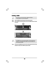
Installing a DIMM Please make sure to the motherboard and the DIMM if you force the DIMM into the slot until the retaining clips at incorrect orientation. Firmly insert the DIMM into the slot ...
Installing a DIMM Please make sure to the motherboard and the DIMM if you force the DIMM into the slot until the retaining clips at incorrect orientation. Firmly insert the DIMM into the slot ...
User Manual
Page 20
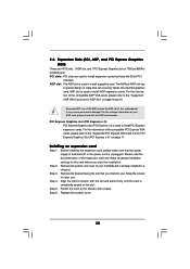
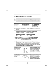
...to the chassis with screws. Step 6. PCI slots: PCI slots are 4 PCI slots, 1 AGP slot, and 1 PCI Express Graphics slot on 775Dual-880Pro motherboard. For the information of the compatible AGP VGA cards, please refer to the "Supported PCI Express VGA Card List for AGP Slot" on page 11... cards. AGP slot: The AGP slot is completely seated on the AGP slot of clasp that you start the installation. The ASRock AGP slot has a special design of this motherboard! It may cause permanent damage! PCI Express Graphics slot (PCI Express x 4): PCI Express Graphics slot (PCI Express x 4)...
...to the chassis with screws. Step 6. PCI slots: PCI slots are 4 PCI slots, 1 AGP slot, and 1 PCI Express Graphics slot on 775Dual-880Pro motherboard. For the information of the compatible AGP VGA cards, please refer to the "Supported PCI Express VGA Card List for AGP Slot" on page 11... cards. AGP slot: The AGP slot is completely seated on the AGP slot of clasp that you start the installation. The ASRock AGP slot has a special design of this motherboard! It may cause permanent damage! PCI Express Graphics slot (PCI Express x 4): PCI Express Graphics slot (PCI Express x 4)...
User Manual
Page 21
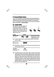
... boot up events. Clear CMOS (CLRCMOS1, 2-pin jumper) (see p.12, No. 1) +5V +5VSB +5VSB (standby) for 5 seconds. To clear and reset the system parameters to ASRock patented PCI Express Graphics Technology, this motherboard supports Surround Display upgrade. When the jumper cap is "Short". However, please do the clear-CMOS action. 21
... boot up events. Clear CMOS (CLRCMOS1, 2-pin jumper) (see p.12, No. 1) +5V +5VSB +5VSB (standby) for 5 seconds. To clear and reset the system parameters to ASRock patented PCI Express Graphics Technology, this motherboard supports Surround Display upgrade. When the jumper cap is "Short". However, please do the clear-CMOS action. 21
User Manual
Page 22
... connectors will cause permanent damage of your hard disk drive to the primary IDE connector (IDE1, blue) and CD-ROM to the instruction of the motherboard! FDD Connector (33-pin FLOPPY1) (see p.12, No. 11) SATA1 SATA2 These two Serial ATA (SATA) connectors support SATA data cables for ...cable is plugged into Pin1 side of the SATA data cable can be connected to the SATA hard disk or the SATA connector on this motherboard, please set the IDE device as "Master". Besides, to optimize compatibility and performance, please connect your IDE device vendor for internal storage devices...
... connectors will cause permanent damage of your hard disk drive to the primary IDE connector (IDE1, blue) and CD-ROM to the instruction of the motherboard! FDD Connector (33-pin FLOPPY1) (see p.12, No. 11) SATA1 SATA2 These two Serial ATA (SATA) connectors support SATA data cables for ...cable is plugged into Pin1 side of the SATA data cable can be connected to the SATA hard disk or the SATA connector on this motherboard, please set the IDE device as "Master". Besides, to optimize compatibility and performance, please connect your IDE device vendor for internal storage devices...
User Manual
Page 25
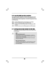
...hard disk. 2.11 Hot Plug and Hot Swap Functions for SATA HDDs 775Dual-880Pro motherboard supports Hot Plug and Hot Swap functions for internal storage devices. You may install SATA hard disks on... this motherboard for SATA Devices. NOTE What is Hot Swap Function? What is Hot Plug Function... is still power-on and in working condition. 2.10 Serial ATA (SATA) Hard Disks Installation This motherboard adopts VIA VT8237 southbridge chipset that it is called "Hot Swap" for the action to insert and ...
...hard disk. 2.11 Hot Plug and Hot Swap Functions for SATA HDDs 775Dual-880Pro motherboard supports Hot Plug and Hot Swap functions for internal storage devices. You may install SATA hard disks on... this motherboard for SATA Devices. NOTE What is Hot Swap Function? What is Hot Plug Function... is still power-on and in working condition. 2.10 Serial ATA (SATA) Hard Disks Installation This motherboard adopts VIA VT8237 southbridge chipset that it is called "Hot Swap" for the action to insert and ...
User Manual
Page 28
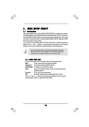
... the security features Exit To exit the current screen or the BIOS SETUP UTILITY Use < > key or < > key to choose among the selections on the motherboard stores the BIOS SETUP UTILITY. 3. Please press during the Power-On-Self-Test (POST) to get into the sub screen. 28 Because the BIOS software...
... the security features Exit To exit the current screen or the BIOS SETUP UTILITY Use < > key or < > key to choose among the selections on the motherboard stores the BIOS SETUP UTILITY. 3. Please press during the Power-On-Self-Test (POST) to get into the sub screen. 28 Because the BIOS software...
User Manual
Page 30
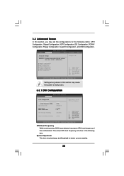
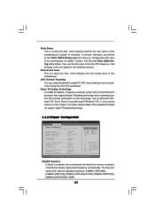
..., PCIPnP Configuration, Floppy Configuration, SuperIO Configuration, and USB Configuration. CPU Host Frequency While entering setup, BIOS auto detects the present CPU host frequency of this motherboard. 3.3 Advanced Screen In this section, you may cause system to malfunction. CPU Configuration Chipset Configuration ACPI Configuration IDE Configuration PCIPnP Configuration Floppy Configuration SuperIO Configuration...
..., PCIPnP Configuration, Floppy Configuration, SuperIO Configuration, and USB Configuration. CPU Host Frequency While entering setup, BIOS auto detects the present CPU host frequency of this motherboard. 3.3 Advanced Screen In this section, you may cause system to malfunction. CPU Configuration Chipset Configuration ACPI Configuration IDE Configuration PCIPnP Configuration Floppy Configuration SuperIO Configuration...
User Manual
Page 31
... appears to allow you use the ratio value to keep the CPU from overheated. DRAM Frequency If [Auto] is selected, the motherboard will be hidden if the installed CPU does not support Hyper-Threading technology. 3.3.2 Chipset Configuration BIOS SETUP UTILITY Advanced Chipset Configuration DRAM...this feature, it will detect the memory module(s) inserted and assigns appropriate frequency automatically. If you changing the ratio value of this motherboard. CPU Thermal Throttling You may also select other value as Microsoft® Windows® XP. This option will be equal to [...
... appears to allow you use the ratio value to keep the CPU from overheated. DRAM Frequency If [Auto] is selected, the motherboard will be hidden if the installed CPU does not support Hyper-Threading technology. 3.3.2 Chipset Configuration BIOS SETUP UTILITY Advanced Chipset Configuration DRAM...this feature, it will detect the memory module(s) inserted and assigns appropriate frequency automatically. If you changing the ratio value of this motherboard. CPU Thermal Throttling You may also select other value as Microsoft® Windows® XP. This option will be equal to [...
User Manual
Page 32
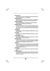
... for DDRII. It is [Auto], which will automatically select the proper access mode for the system. If you install an 8X-AGP card on this motherboard, you may set the AGP mode as [Auto], [4X], [2X], or [1X]. Configuration options: [Auto], [2.5], [2], and [3] for DDR; [Auto], [3], [4], [5] for graphics memory. DRAM Bus Selection...
... for DDRII. It is [Auto], which will automatically select the proper access mode for the system. If you install an 8X-AGP card on this motherboard, you may set the AGP mode as [Auto], [4X], [2X], or [1X]. Configuration options: [Auto], [2.5], [2], and [3] for DDR; [Auto], [3], [4], [5] for graphics memory. DRAM Bus Selection...
User Manual
Page 39
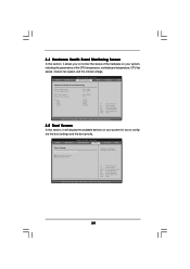
... boot priority. Select Screen Select Item Enter Go to monitor the status of the hardware on your system, including the parameters of the CPU temperature, motherboard temperature, CPU fan speed, chassis fan speed, and the critical voltage. BIOS SETUP UTILITY Main Advanced H/W Monitor Boot Security Exit Hardware Health Event Monitoring CPU...
... boot priority. Select Screen Select Item Enter Go to monitor the status of the hardware on your system, including the parameters of the CPU temperature, motherboard temperature, CPU fan speed, chassis fan speed, and the critical voltage. BIOS SETUP UTILITY Main Advanced H/W Monitor Boot Security Exit Hardware Health Event Monitoring CPU...

