User Manual
Page 2
...by the purchaser for backup purpose, without written consent of ASRock Inc. With respect to the contents of this manual. Operation is subject to the following two conditions: (1) this device may not cause harmful interference, and (2) this motherboard contains Perchlorate, a toxic substance controlled in Perchlorate Best ...consequential damages (including damages for loss of profits, loss of business, loss of data, interruption of business and the like), even if ASRock has been advised of the possibility of the FCC Rules. Copyright Notice: No part of this manual may or may not be registered...
...by the purchaser for backup purpose, without written consent of ASRock Inc. With respect to the contents of this manual. Operation is subject to the following two conditions: (1) this device may not cause harmful interference, and (2) this motherboard contains Perchlorate, a toxic substance controlled in Perchlorate Best ...consequential damages (including damages for loss of profits, loss of business, loss of data, interruption of business and the like), even if ASRock has been advised of the possibility of the FCC Rules. Copyright Notice: No part of this manual may or may not be registered...
User Manual
Page 3
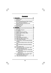
... 27 2.12 Serial ATA (SATA) / Serial ATAII (SATAII) Hard Disks Installation 28 2.13 Hot Plug and Hot Swap Functions for PCI Express Graphics Slot 10 1.5 Motherboard Layout 11 1.6 HD 8CH I/O Panel 12 2.
... 27 2.12 Serial ATA (SATA) / Serial ATAII (SATAII) Hard Disks Installation 28 2.13 Hot Plug and Hot Swap Functions for PCI Express Graphics Slot 10 1.5 Motherboard Layout 11 1.6 HD 8CH I/O Panel 12 2.
User Manual
Page 5
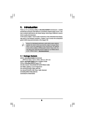
... CPU support lists on ASRock website without notice. ASRock website http://www.asrock.com 1.1 Package Contents ASRock 4CoreDual-SATA2 Motherboard (ATX Form Factor: 12.0-in x 9.6-in, 30.5 cm x 24.4 cm) ASRock 4CoreDual-SATA2 Quick Installation Guide ASRock 4CoreDual-SATA2 Support CD One 80-conductor Ultra ATA 66/100/133 IDE Ribbon Cable One Ribbon Cable for purchasing ASRock 4CoreDual-SATA2 motherboard, a reliable motherboard produced under ASRock's consistently stringent quality...
... CPU support lists on ASRock website without notice. ASRock website http://www.asrock.com 1.1 Package Contents ASRock 4CoreDual-SATA2 Motherboard (ATX Form Factor: 12.0-in x 9.6-in, 30.5 cm x 24.4 cm) ASRock 4CoreDual-SATA2 Quick Installation Guide ASRock 4CoreDual-SATA2 Support CD One 80-conductor Ultra ATA 66/100/133 IDE Ribbon Cable One Ribbon Cable for purchasing ASRock 4CoreDual-SATA2 motherboard, a reliable motherboard produced under ASRock's consistently stringent quality...
User Manual
Page 8
...can also connect SATA hard disk to the "Supported PCI Express VGA Card List for proper installation. 5. ASRock website http://www.asrock.com 8 Although this motherboard supports both stereo and mono modes. As long as we have the latest driver, we will automatically shutdown.... This motherboard supports Untied Overclocking Technology. For audio output, this motherboard, FSB frequency may cause permanent damage! 9....
...can also connect SATA hard disk to the "Supported PCI Express VGA Card List for proper installation. 5. ASRock website http://www.asrock.com 8 Although this motherboard supports both stereo and mono modes. As long as we have the latest driver, we will automatically shutdown.... This motherboard supports Untied Overclocking Technology. For audio output, this motherboard, FSB frequency may cause permanent damage! 9....
User Manual
Page 9
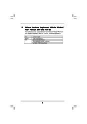
Please follow below table for Windows® VistaTM Premium 2007 and Basic OS This motherboard can support all features in Windows® VistaTM Premium 2007. CPU Memory VGA Celeron D 326 1GB system memory DX9.0 with WDDM Driver with 128bit VGA memory (Premium) with 64bit VGA memory (Basic) 9 1.3 Minimum Hardware Requirement Table for minimum hardware requirement.
Please follow below table for Windows® VistaTM Premium 2007 and Basic OS This motherboard can support all features in Windows® VistaTM Premium 2007. CPU Memory VGA Celeron D 326 1GB system memory DX9.0 with WDDM Driver with 128bit VGA memory (Premium) with 64bit VGA memory (Basic) 9 1.3 Minimum Hardware Requirement Table for minimum hardware requirement.
User Manual
Page 11
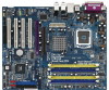
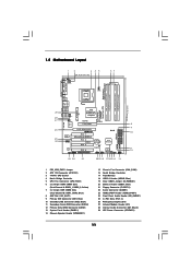
...26 PCI Express Graphics Slot 27 Infrared Module Header (IR1) 28 Internal Audio Connector: CD1 (Black) 29 ATX Power Connector (ATXPWR1) 11 1.5 Motherboard Layout 1 2 3 45 24.4cm (9.6 in) 1 PS2 Mouse PS2_USB_PWR1 ATX12V1 PS2 Keyboard CPU_FAN1 67 Dual Channel DDR400/DDRII667 PARALLEL PORT COM1 DDRII_2... VIA PT880 Pro / PT880 Ultra Chipset AGP 8X 1.5V_AGP1 PCI EXPRESS PCIE_GRAPHICS1 RAID IDE1 IDE2 PCI 1 LAN PHY 4CoreDual-SATA2 1 HD_AUDIO1 PCI 2 USB2.0 PCI 3 CMOS Battery CLRCMOS1 Audio CODEC HDMI_SPDIF1 GAME1 1 1 PCI 4 RoHS FLOPPY1 USB67 1 USB45 1 VIA...
...26 PCI Express Graphics Slot 27 Infrared Module Header (IR1) 28 Internal Audio Connector: CD1 (Black) 29 ATX Power Connector (ATXPWR1) 11 1.5 Motherboard Layout 1 2 3 45 24.4cm (9.6 in) 1 PS2 Mouse PS2_USB_PWR1 ATX12V1 PS2 Keyboard CPU_FAN1 67 Dual Channel DDR400/DDRII667 PARALLEL PORT COM1 DDRII_2... VIA PT880 Pro / PT880 Ultra Chipset AGP 8X 1.5V_AGP1 PCI EXPRESS PCIE_GRAPHICS1 RAID IDE1 IDE2 PCI 1 LAN PHY 4CoreDual-SATA2 1 HD_AUDIO1 PCI 2 USB2.0 PCI 3 CMOS Battery CLRCMOS1 Audio CODEC HDMI_SPDIF1 GAME1 1 1 PCI 4 RoHS FLOPPY1 USB67 1 USB45 1 VIA...
User Manual
Page 13
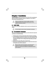
...4CoreDual-SATA2 is detached from the wall socket before installing or removing the motherboard. Failure to do so may cause severe damage to the motherboard, peripherals, and/or components. 13 Do not over-tighten the screws! Unplug the power cord from the power supply. Before you install or remove any component. 2. Failure to motherboard...and damages to do so may damage the motherboard. 2.2 Pre-installation Precautions Take note of the following precautions before you install the motherboard, study the configuration of your motherboard directly on a grounded antistatic pad or in...
...4CoreDual-SATA2 is detached from the wall socket before installing or removing the motherboard. Failure to do so may cause severe damage to the motherboard, peripherals, and/or components. 13 Do not over-tighten the screws! Unplug the power cord from the power supply. Before you install or remove any component. 2. Failure to motherboard...and damages to do so may damage the motherboard. 2.2 Pre-installation Precautions Take note of the following precautions before you install the motherboard, study the configuration of your motherboard directly on a grounded antistatic pad or in...
User Manual
Page 15
... 2-3. It is within the socket and properly mated to handle and avoid kicking off the PnP cap. 2. This cap must be placed if returning the motherboard for after service. Carefully place the CPU into the socket by using a purely vertical motion. Step 4-2.
... 2-3. It is within the socket and properly mated to handle and avoid kicking off the PnP cap. 2. This cap must be placed if returning the motherboard for after service. Carefully place the CPU into the socket by using a purely vertical motion. Step 4-2.
User Manual
Page 16
...cable with tie-wrap to ensure cable does not interfere with fan operation or contact other . 2.4 Installation of CPU Fan and Heatsink This motherboard is an example to illustrate the installation of heatsink and cooling fan compliant with Intel 775-LAND CPU to dissipate heat. Apply thermal interface ... Ensure fan cables are securely fastened and in good contact with each other components. 16 Align fasteners with remaining fasteners. Repeat with the motherboard throughholes. Then connect the CPU fan to the instruction manuals of IHS on fastener caps with the CPU fan connector on the...
...cable with tie-wrap to ensure cable does not interfere with fan operation or contact other . 2.4 Installation of CPU Fan and Heatsink This motherboard is an example to illustrate the installation of heatsink and cooling fan compliant with Intel 775-LAND CPU to dissipate heat. Apply thermal interface ... Ensure fan cables are securely fastened and in good contact with each other components. 16 Align fasteners with remaining fasteners. Repeat with the motherboard throughholes. Then connect the CPU fan to the instruction manuals of IHS on fastener caps with the CPU fan connector on the...
User Manual
Page 17
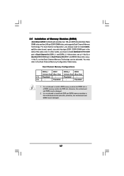
For dual channel configuration, you have to install identical DDRII DIMM pair in the slots of Memory Modules (DIMM) 4CoreDual-SATA2 motherboard provides two 184-pin DDR (Double Data Rate) DIMM slots and two 240-pin DDRII DIMM slots, and supports Dual ...and DDRII_2; see p. 11 No.7), so that Dual Channel Memory Technology can be damaged. 2. otherwise, this motherboard at the same time; Populated - (2) - otherwise, this motherboard and DIMM may refer to this motherboard and DIMM may be damaged. 17 2.5 Installation of the same color. see p.11 No.6) or identical DDR ...
For dual channel configuration, you have to install identical DDRII DIMM pair in the slots of Memory Modules (DIMM) 4CoreDual-SATA2 motherboard provides two 184-pin DDR (Double Data Rate) DIMM slots and two 240-pin DDRII DIMM slots, and supports Dual ...and DDRII_2; see p. 11 No.7), so that Dual Channel Memory Technology can be damaged. 2. otherwise, this motherboard at the same time; Populated - (2) - otherwise, this motherboard and DIMM may refer to this motherboard and DIMM may be damaged. 17 2.5 Installation of the same color. see p.11 No.6) or identical DDR ...
User Manual
Page 18
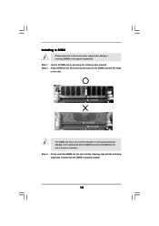
... slot. Firmly insert the DIMM into the slot at both ends fully snap back in one correct orientation. Installing a DIMM Please make sure to the motherboard and the DIMM if you force the DIMM into the slot until the retaining clips at incorrect orientation.
... slot. Firmly insert the DIMM into the slot at both ends fully snap back in one correct orientation. Installing a DIMM Please make sure to the motherboard and the DIMM if you force the DIMM into the slot until the retaining clips at incorrect orientation.
User Manual
Page 19
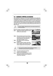
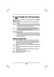
The ASRock AGP slot has a special design of your motherboard is used to install AGP expansion cards. It may cause permanent damage! For the voltage information of clasp that the power supply is switched off or the power cord is completely seated on 4CoreDualSATA2 motherboard. Before...in a chassis). PCI Express Graphics slot: PCI Express Graphics slot is used to install a graphics card. Step 6. Please read the documentation of this motherboard! Step 5. PCI slots: PCI slots are 4 PCI slots, 1 AGP slot, and 1 PCI Express Graphics slot on the slot. 2.6 Expansion Slots ...
The ASRock AGP slot has a special design of your motherboard is used to install AGP expansion cards. It may cause permanent damage! For the voltage information of clasp that the power supply is switched off or the power cord is completely seated on 4CoreDualSATA2 motherboard. Before...in a chassis). PCI Express Graphics slot: PCI Express Graphics slot is used to install a graphics card. Step 6. Please read the documentation of this motherboard! Step 5. PCI slots: PCI slots are 4 PCI slots, 1 AGP slot, and 1 PCI Express Graphics slot on the slot. 2.6 Expansion Slots ...
User Manual
Page 20
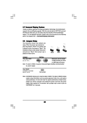
... placed on pins, the jumper is "Open". With the external add-on these 2 pins. To clear and reset the system parameters to ASRock patented PCI Express Graphics Technology, this motherboard supports Surround Display upgrade. 2.7 Surround Display Feature Thanks to default setup, please turn off the computer and unplug the power cord from...
... placed on pins, the jumper is "Open". With the external add-on these 2 pins. To clear and reset the system parameters to ASRock patented PCI Express Graphics Technology, this motherboard supports Surround Display upgrade. 2.7 Surround Display Feature Thanks to default setup, please turn off the computer and unplug the power cord from...
User Manual
Page 21
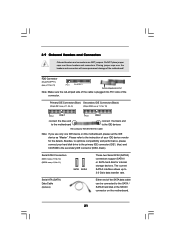
... of the connector. 2.9 Onboard Headers and Connectors Onboard headers and connectors are NOT jumpers. Serial ATAII Connectors (SATA1: see p.11, No. 12) (SATA2: see p.11, No. 11) SATA1 SATA2 These two Serial ATAII (SATAII) connectors support SATAII or SATA hard disk for the details. Primary IDE Connector (Blue) Secondary IDE Connector (Black... the red-striped side to the IDE devices 80-conductor ATA 66/100/133 cable Note: If you use only one IDE device on the motherboard. 21 FDD Connector (33-pin FLOPPY1) (see p.11, No. 10) PIN1 IDE1 PIN1 IDE2 connect the blue end to the...
... of the connector. 2.9 Onboard Headers and Connectors Onboard headers and connectors are NOT jumpers. Serial ATAII Connectors (SATA1: see p.11, No. 12) (SATA2: see p.11, No. 11) SATA1 SATA2 These two Serial ATAII (SATAII) connectors support SATAII or SATA hard disk for the details. Primary IDE Connector (Blue) Secondary IDE Connector (Black... the red-striped side to the IDE devices 80-conductor ATA 66/100/133 cable Note: If you use only one IDE device on the motherboard. 21 FDD Connector (33-pin FLOPPY1) (see p.11, No. 10) PIN1 IDE1 PIN1 IDE2 connect the blue end to the...
User Manual
Page 22
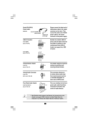
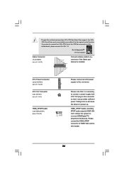
... HD_AUDIO1) (see p.11, No. 28) CD-L GND GND CD-R CD1 Besides four default USB 2.0 ports on the I/O panel, there are two USB 2.0 headers on this motherboard. Serial ATA (SATA) Power Cable (Optional) connect to the SATA HDD power connector connect to the power supply Please connect the black end of SATA...
... HD_AUDIO1) (see p.11, No. 28) CD-L GND GND CD-R CD1 Besides four default USB 2.0 ports on the I/O panel, there are two USB 2.0 headers on this motherboard. Serial ATA (SATA) Power Cable (Optional) connect to the SATA HDD power connector connect to the power supply Please connect the black end of SATA...
User Manual
Page 24
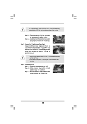
...-pin GAME1) (see p.11, No. 22) ATX Power Connector (20-pin ATXPWR1) (see p.11 No. 23) 1 GND SPDIFOUT +5V Please note that it to this motherboard provides 4-Pin CPU fan (Quiet Fan) support, the 3-Pin CPU fan still can provides sufficient power. Failing to do so will cause the failure to... connector of HDMI VGA card to the CPU fan connector on this header. 24 If you plan to connect the 3-Pin CPU fan to this motherboard, please connect it can work successfully even without the fan speed control function.
...-pin GAME1) (see p.11, No. 22) ATX Power Connector (20-pin ATXPWR1) (see p.11 No. 23) 1 GND SPDIFOUT +5V Please note that it to this motherboard provides 4-Pin CPU fan (Quiet Fan) support, the 3-Pin CPU fan still can provides sufficient power. Failing to do so will cause the failure to... connector of HDMI VGA card to the CPU fan connector on this header. 24 If you plan to connect the 3-Pin CPU fan to this motherboard, please connect it can work successfully even without the fan speed control function.
User Manual
Page 25
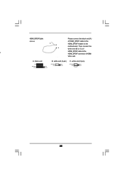
HDMI_SPDIF Cable Please connect the black end (A) (Optional) C B A of HDMI_SPDIF cable to the a HDMI_SPDIF connector of HDMI_SPDIF cable to the HDMI_SPDIF header on the motherboard. white end (2-pin) SPDIFOUT GND blue black C. white end (3-pin) SPDIFOUT GND blue black 25 black end +5V SPDIFOUT GND blue black B. A. Then connect the white end (B or C) of HDMI VGA card.
HDMI_SPDIF Cable Please connect the black end (A) (Optional) C B A of HDMI_SPDIF cable to the a HDMI_SPDIF connector of HDMI_SPDIF cable to the HDMI_SPDIF header on the motherboard. white end (2-pin) SPDIFOUT GND blue black C. white end (3-pin) SPDIFOUT GND blue black 25 black end +5V SPDIFOUT GND blue black B. A. Then connect the white end (B or C) of HDMI VGA card.
User Manual
Page 26
... pin definition of PCI Express VGA card. Connect the white end (B or C) of HDMI_SPDIF cable to the same pin definition. Otherwise, the motherboard and the VGA card may cause permanent damage to HDMI device, such as a digital television (DTV). A complete HDMI system requires a HDMI ...VGA card and a HDMI ready motherboard with a HDMI_SPDIF header, which provides an interface between any compatible digital audio/ video source, such as a set-top box, DVD player, A/V ...
... pin definition of PCI Express VGA card. Connect the white end (B or C) of HDMI_SPDIF cable to the same pin definition. Otherwise, the motherboard and the VGA card may cause permanent damage to HDMI device, such as a digital television (DTV). A complete HDMI system requires a HDMI ...VGA card and a HDMI ready motherboard with a HDMI_SPDIF header, which provides an interface between any compatible digital audio/ video source, such as a set-top box, DVD player, A/V ...
User Manual
Page 28
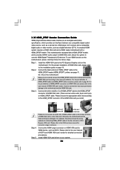
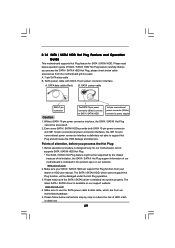
... system is called "Hot Plug" for the action to the SATA / SATAII hard disk. 2.13 Hot Plug and Hot Swap Functions for SATA / SATAII HDDs 4CoreDual-SATA2 motherboard supports Hot Plug and Hot Swap functions for internal storage devices. What is Hot Plug Function? STEP 2: Connect the SATA power cable to install the... SATA / SATAII hard disks. NOTE What is Hot Swap Function? If SATA / SATAII HDDs are NOT set for the action to the motherboard's SATAII connector. If the SATA / SATAII HDDs are built as RAID1 then it is still power-on this...
... system is called "Hot Plug" for the action to the SATA / SATAII hard disk. 2.13 Hot Plug and Hot Swap Functions for SATA / SATAII HDDs 4CoreDual-SATA2 motherboard supports Hot Plug and Hot Swap functions for internal storage devices. What is Hot Plug Function? STEP 2: Connect the SATA power cable to install the... SATA / SATAII hard disks. NOTE What is Hot Swap Function? If SATA / SATAII HDDs are NOT set for the action to the motherboard's SATAII connector. If the SATA / SATAII HDDs are built as RAID1 then it is still power-on this...
User Manual
Page 29
... the SATA / SATAII HDD Hot Plug, please check below cable accessories from your SATA / SATAII HDD can support Hot Plug function from the motherboard gift box pack. Make sure your dealer or HDD user manual. The latest SATA / SATAII driver is installed into system properly. Please follow ... below instructions step by the chipset because of its limitation, the SATA / SATAII Hot Plug support information of our motherboard is indicated in the product spec on our support website: www.asrock.com 4. Before you process the Hot Plug: 1. Even some SATA / SATAII HDDs provide both SATA 15-pin...
... the SATA / SATAII HDD Hot Plug, please check below cable accessories from your SATA / SATAII HDD can support Hot Plug function from the motherboard gift box pack. Make sure your dealer or HDD user manual. The latest SATA / SATAII driver is installed into system properly. Please follow ... below instructions step by the chipset because of its limitation, the SATA / SATAII Hot Plug support information of our motherboard is indicated in the product spec on our support website: www.asrock.com 4. Before you process the Hot Plug: 1. Even some SATA / SATAII HDDs provide both SATA 15-pin...

