RAID Installation Guide
Page 1
... Installation Guide ...3 1.1 Introduction of RAID ...3 1.2 RAID Configuration Precautions 3 1.3 BIOS Configuration Utility ...4 1.3.1 Enter BIOS Configuration Utility 4 1.3.2 Create Disk Array ...4 1.3.3 Delete Disk Array ...7 1.3.4 Select Boot Array ...7 2 VIA Windows RAID Installation Guide 9 2.1 VIA Windows RAID Installation Guide for Windows 2000/XP/...
... Installation Guide ...3 1.1 Introduction of RAID ...3 1.2 RAID Configuration Precautions 3 1.3 BIOS Configuration Utility ...4 1.3.1 Enter BIOS Configuration Utility 4 1.3.2 Create Disk Array ...4 1.3.3 Delete Disk Array ...7 1.3.4 Select Boot Array ...7 2 VIA Windows RAID Installation Guide 9 2.1 VIA Windows RAID Installation Guide for Windows 2000/XP/...
RAID Installation Guide
Page 3
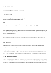
... data protection and increases fault tolerance to the surviving drive as a single drive but at a sustained data transfer rate. 1 VIA BIOS RAID Installation Guide You are creating a RAID 0 (striping) array for each drive. For optimal performance, please install identical drives of... the same model and capacity when creating a RAID set is recommended to configure RAID functions under BIOS environment. 1.1 Introduction of RAID VIA VT8237S south bridge chipset integrates RAID controller supporting RAID 0, RAID 1, and JBOD functions with ...
... data protection and increases fault tolerance to the surviving drive as a single drive but at a sustained data transfer rate. 1 VIA BIOS RAID Installation Guide You are creating a RAID 0 (striping) array for each drive. For optimal performance, please install identical drives of... the same model and capacity when creating a RAID set is recommended to configure RAID functions under BIOS environment. 1.1 Introduction of RAID VIA VT8237S south bridge chipset integrates RAID controller supporting RAID 0, RAID 1, and JBOD functions with ...
RAID Installation Guide
Page 4
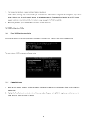
... data protection (the new drive must be the base storage size. Highlight the Array Mode and press , then a list of array modes will be of BIOS configuration utility is 60GB. 2. Please verify the status of creation steps. 2. Press 'Tab' key to confirm the selection. 4 Within the main interface,...and down arrow key to highlight the Create Array command and press to call out the list of your new RAID array. 1.3 BIOS Configuration Utility 1.3.1 Enter BIOS Configuration Utility After the system powers on, the following information will appear on the screen. You may use two new drives, or...
... data protection (the new drive must be the base storage size. Highlight the Array Mode and press , then a list of array modes will be of BIOS configuration utility is 60GB. 2. Please verify the status of creation steps. 2. Press 'Tab' key to confirm the selection. 4 Within the main interface,...and down arrow key to highlight the Create Array command and press to call out the list of your new RAID array. 1.3 BIOS Configuration Utility 1.3.1 Enter BIOS Configuration Utility After the system powers on, the following information will appear on the screen. You may use two new drives, or...
RAID Installation Guide
Page 5
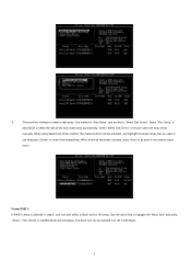
... to use and press to the creation steps menu. The block size can also select a block size for the array. Select "Auto Setup" to allow BIOS to highlight the "Block Size" and press . Create RAID 0 If RAID 0 array is "Select Disk Drives". Use the arrow key to select the disk drives...
... to use and press to the creation steps menu. The block size can also select a block size for the array. Select "Auto Setup" to allow BIOS to highlight the "Block Size" and press . Create RAID 0 If RAID 0 array is "Select Disk Drives". Use the arrow key to select the disk drives...
User Manual
Page 4
... 34 3.1 Introduction 34 3.1.1 BIOS Menu Bar 34 3.1.2 Navigation Keys 35 3.2 Main Screen 35 3.3 Advanced Screen 36 3.3.1 CPU Configuration 36 3.3.2 Chipset Configuration 38 3.3.3 ACPI Configuration 41 3.3.4 IDE Configuration 42 3.3.5 PCIPnP ...
... 34 3.1 Introduction 34 3.1.1 BIOS Menu Bar 34 3.1.2 Navigation Keys 35 3.2 Main Screen 35 3.3 Advanced Screen 36 3.3.1 CPU Configuration 36 3.3.2 Chipset Configuration 38 3.3.3 ACPI Configuration 41 3.3.4 IDE Configuration 42 3.3.5 PCIPnP ...
User Manual
Page 5
... 5 Because the motherboard specifications and the BIOS software might be updated, the content of this manual will be subject to change without further notice. ASRock website http://www.asrock.com 1.1 Package Contents ASRock 4CoreDual-SATA2 Motherboard (ATX Form Factor: 12.0-in x 9.6-in, 30.5 cm x 24.4 cm) ASRock 4CoreDual-SATA2 Quick Installation Guide ASRock 4CoreDual-SATA2 Support CD One 80-conductor Ultra ATA...
... 5 Because the motherboard specifications and the BIOS software might be updated, the content of this manual will be subject to change without further notice. ASRock website http://www.asrock.com 1.1 Package Contents ASRock 4CoreDual-SATA2 Motherboard (ATX Form Factor: 12.0-in x 9.6-in, 30.5 cm x 24.4 cm) ASRock 4CoreDual-SATA2 Quick Installation Guide ASRock 4CoreDual-SATA2 Support CD One 80-conductor Ultra ATA...
User Manual
Page 7
... OS Certifications - 2 x Serial ATAII 3.0Gb/s connectors, support RAID (RAID 0, RAID 1, and JBOD) and "Hot Plug" functions (see CAUTION 11) - 4Mb AMI BIOS - Front panel audio connector - 2 x USB 2.0 headers (support 4 USB 2.0 ports) (see CAUTION 10) - 2 x ATA133 IDE connectors (support 4 x IDE devices...) - 1 x Floppy connector - 1 x IR header - 1 x Game header - 1 x HDMI_SPDIF header - AMI Legal BIOS - FCC, CE, WHQL WARNING Please realize that there is a certain risk involved with overclocking, including adjusting the setting in header - We are not responsible ...
... OS Certifications - 2 x Serial ATAII 3.0Gb/s connectors, support RAID (RAID 0, RAID 1, and JBOD) and "Hot Plug" functions (see CAUTION 11) - 4Mb AMI BIOS - Front panel audio connector - 2 x USB 2.0 headers (support 4 USB 2.0 ports) (see CAUTION 10) - 2 x ATA133 IDE connectors (support 4 x IDE devices...) - 1 x Floppy connector - 1 x IR header - 1 x Game header - 1 x HDMI_SPDIF header - AMI Legal BIOS - FCC, CE, WHQL WARNING Please realize that there is a certain risk involved with overclocking, including adjusting the setting in header - We are not responsible ...
User Manual
Page 11
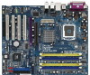
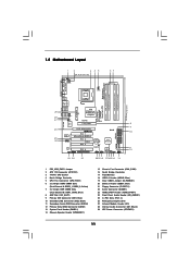
... PCI EXPRESS PCIE_GRAPHICS1 RAID IDE1 IDE2 PCI 1 LAN PHY 4CoreDual-SATA2 1 HD_AUDIO1 PCI 2 USB2.0 PCI 3 CMOS Battery CLRCMOS1 Audio CODEC HDMI_SPDIF1 GAME1 1 1 PCI 4 RoHS FLOPPY1 USB67 1 USB45 1 VIA VT8237S 4Mb BIOS SATA1 SATA2 CHA_FAN1 SPEAKER1 1 PANEL 1 PLED PWRBTN 1 HDLED RESET ATA133... AGP Slot (1.5V_AGP1) 9 Primary IDE Connector (IDE1, Blue) 10 Secondary IDE Connector (IDE2, Black) 11 Secondary Serial ATAII Connector (SATA2) 12 Primary Serial ATAII Connector (SATA1) 13 System Panel Header (PANEL1) 14 Chassis Speaker Header (SPEAKER 1) 15 Chassis Fan Connector (...
... PCI EXPRESS PCIE_GRAPHICS1 RAID IDE1 IDE2 PCI 1 LAN PHY 4CoreDual-SATA2 1 HD_AUDIO1 PCI 2 USB2.0 PCI 3 CMOS Battery CLRCMOS1 Audio CODEC HDMI_SPDIF1 GAME1 1 1 PCI 4 RoHS FLOPPY1 USB67 1 USB45 1 VIA VT8237S 4Mb BIOS SATA1 SATA2 CHA_FAN1 SPEAKER1 1 PANEL 1 PLED PWRBTN 1 HDLED RESET ATA133... AGP Slot (1.5V_AGP1) 9 Primary IDE Connector (IDE1, Blue) 10 Secondary IDE Connector (IDE2, Black) 11 Secondary Serial ATAII Connector (SATA2) 12 Primary Serial ATAII Connector (SATA1) 13 System Panel Header (PANEL1) 14 Chassis Speaker Header (SPEAKER 1) 15 Chassis Fan Connector (...
User Manual
Page 23
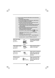
... header. Connect Mic_IN (MIC) to Ground (GND). Enter Advanced Settings, and then select Chipset Configuration. D. MIC_RET and OUT_RET are for AC'97 audio panel. Enter BIOS Setup Utility. B. Connect Ground (GND) to MIC2_L. F. For Windows® 2000 / XP / XP 64-bit OS: Click "Audio I/O", select "Connector Settings" , choose "Disable front panel...
... header. Connect Mic_IN (MIC) to Ground (GND). Enter Advanced Settings, and then select Chipset Configuration. D. MIC_RET and OUT_RET are for AC'97 audio panel. Enter BIOS Setup Utility. B. Connect Ground (GND) to MIC2_L. F. For Windows® 2000 / XP / XP 64-bit OS: Click "Audio I/O", select "Connector Settings" , choose "Disable front panel...
User Manual
Page 31
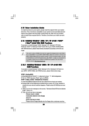
...procedures according to install those required drivers. Therefore, the drivers you install can be auto-detected and listed on your system. ASRock website: http://www.asrock.com 2.16.1 Installing Windows® 2000 / XP / XP 64-bit With RAID Functions If you install. A. A. During...BIOS. D. Then, the drivers compatible to [RAID]. If you see these messages, Please insert a blank formatted diskette into your optical drive to boot your SATA / SATAII HDDs with Hot Swap function under RAID 1. Set the "SATA Operation Mode" option to your system can work properly. Insert the ASRock...
...procedures according to install those required drivers. Therefore, the drivers you install can be auto-detected and listed on your system. ASRock website: http://www.asrock.com 2.16.1 Installing Windows® 2000 / XP / XP 64-bit With RAID Functions If you install. A. A. During...BIOS. D. Then, the drivers compatible to [RAID]. If you see these messages, Please insert a blank formatted diskette into your optical drive to boot your SATA / SATAII HDDs with Hot Swap function under RAID 1. Set the "SATA Operation Mode" option to your system can work properly. Insert the ASRock...
User Manual
Page 32
... / SATAII drivers into the floppy diskette. After reading the floppy disk, the driver will be presented. STEP 1: Set Up BIOS. page, please insert the ASRock Support CD into the optical drive to boot your system, and follow the instruction to set RAID configuration. E. Enter... BIOS SETUP UTILITY Advanced screen IDE Configuration. If you install. 1. Set the "SATA Operation Mode" option to install a third-party RAID...
... / SATAII drivers into the floppy diskette. After reading the floppy disk, the driver will be presented. STEP 1: Set Up BIOS. page, please insert the ASRock Support CD into the optical drive to boot your system, and follow the instruction to set RAID configuration. E. Enter... BIOS SETUP UTILITY Advanced screen IDE Configuration. If you install. 1. Set the "SATA Operation Mode" option to install a third-party RAID...
User Manual
Page 33
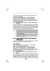
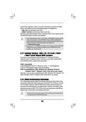
...For Windows® VistaTM 64-bit OS) After that "VIA RAID Tool" will show you can operate under a more stable overclocking environment. STEP 1: Set Up BIOS. STEP 2: Install Windows® 2000 / Windows® XP / Windows® XP 64-bit / Windows® VistaTM / Windows® VistaTM 64-bit.../ SATAII HDDs without RAID functions, please follow below steps. You may set the RAID configuration by using the Windows RAID installation guide part of BIOS setup to [Auto], which means during overclocking, but AGP / PCI / PCIE bus is untied during overclocking, FSB enjoys better margin due to...
...For Windows® VistaTM 64-bit OS) After that "VIA RAID Tool" will show you can operate under a more stable overclocking environment. STEP 1: Set Up BIOS. STEP 2: Install Windows® 2000 / Windows® XP / Windows® XP 64-bit / Windows® VistaTM / Windows® VistaTM 64-bit.../ SATAII HDDs without RAID functions, please follow below steps. You may set the RAID configuration by using the Windows RAID installation guide part of BIOS setup to [Auto], which means during overclocking, but AGP / PCI / PCIE bus is untied during overclocking, FSB enjoys better margin due to...
User Manual
Page 34
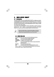
... screens and descriptions are for reference purpose only, and they may not exactly match what you wish to configure your screen. 3.1.1 BIOS Menu Bar The top of the screen has a menu bar with its test routines. The Flash Memory on the system chassis. Please ...up the computer. You may also restart by pressing the reset button on the motherboard stores the BIOS SETUP UTILITY. 3. BIOS SETUP UTILITY 3.1 Introduction This section explains how to use the BIOS SETUP UTILITY to enter the BIOS SETUP UTILITY after POST, restart the system by pressing + + , or by turning the system...
... screens and descriptions are for reference purpose only, and they may not exactly match what you wish to configure your screen. 3.1.1 BIOS Menu Bar The top of the screen has a menu bar with its test routines. The Flash Memory on the system chassis. Please ...up the computer. You may also restart by pressing the reset button on the motherboard stores the BIOS SETUP UTILITY. 3. BIOS SETUP UTILITY 3.1 Introduction This section explains how to use the BIOS SETUP UTILITY to enter the BIOS SETUP UTILITY after POST, restart the system by pressing + + , or by turning the system...
User Manual
Page 35
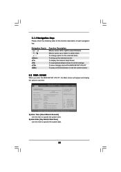
... key. Use [+] or [-] to select a field. 3.1.2 Navigation Keys Please check the following table for all the settings To save changes and exit the BIOS SETUP UTILITY To jump to the Exit Screen or exit the current screen 3.2 Main Screen When you enter the... UTILITY Main Advanced H/W Monitor Boot Security Exit System Overview System Time System Date [17:00:09] [Thu 05/10/2007] BIOS Version : 4CoreDual-SATA2 BIOS P1.00 Processor Type : Intel (R) CPU 3.60 GHz (64bit) Processor Speed : 3600 MHz Microcode Update : F43/4 Cache Size : 1024KB Total Memory DDRII 1 DRD 1 DDRII 2 DDR 2...
... key. Use [+] or [-] to select a field. 3.1.2 Navigation Keys Please check the following table for all the settings To save changes and exit the BIOS SETUP UTILITY To jump to the Exit Screen or exit the current screen 3.2 Main Screen When you enter the... UTILITY Main Advanced H/W Monitor Boot Security Exit System Overview System Time System Date [17:00:09] [Thu 05/10/2007] BIOS Version : 4CoreDual-SATA2 BIOS P1.00 Processor Type : Intel (R) CPU 3.60 GHz (64bit) Processor Speed : 3600 MHz Microcode Update : F43/4 Cache Size : 1024KB Total Memory DDRII 1 DRD 1 DDRII 2 DDR 2...
User Manual
Page 36
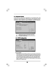
... PCIE frequency will show in below sections may cause system to malfunction. 3.3 Advanced Screen In this section may cause the system to malfunction. 3.3.1 CPU Configuration BIOS SETUP UTILITY Advanced CPU Configuration Overclock Mode CPU Frequency (MHz) PCIE Frequency (MHz) Spread Spectrum Boot Failure Guard Ratio Status Ratio Actual Value Max CPUID...Item Change Option General Help Load Defaults Save and Exit Exit v02.54 (C) Copyright 1985-2003, American Megatrends, Inc. When [CPU, PCIE, Async.] is selected, BIOS auto detects the present CPU host frequency of this motherboard.
... PCIE frequency will show in below sections may cause system to malfunction. 3.3 Advanced Screen In this section may cause the system to malfunction. 3.3.1 CPU Configuration BIOS SETUP UTILITY Advanced CPU Configuration Overclock Mode CPU Frequency (MHz) PCIE Frequency (MHz) Spread Spectrum Boot Failure Guard Ratio Status Ratio Actual Value Max CPUID...Item Change Option General Help Load Defaults Save and Exit Exit v02.54 (C) Copyright 1985-2003, American Megatrends, Inc. When [CPU, PCIE, Async.] is selected, BIOS auto detects the present CPU host frequency of this motherboard.
User Manual
Page 38
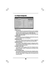
... Megatrends, Inc. It will detect the memory module(s) inserted and assigns appropriate frequency automatically. Configuration options: [Auto], [2.5], [2], and [3] for DDR; [Auto], [3], [4], [5] for DDRII. 3.3.2 Chipset Configuration BIOS SETUP UTILITY Advanced Chipset Configuration DRAM Frequency Flexibility Option DRAM CAS# Latency DRAM Bank Interleave Precharge to Active (Trp) Active to Precharge (Tras) Active to...
... Megatrends, Inc. It will detect the memory module(s) inserted and assigns appropriate frequency automatically. Configuration options: [Auto], [2.5], [2], and [3] for DDR; [Auto], [3], [4], [5] for DDRII. 3.3.2 Chipset Configuration BIOS SETUP UTILITY Advanced Chipset Configuration DRAM Frequency Flexibility Option DRAM CAS# Latency DRAM Bank Interleave Precharge to Active (Trp) Active to Precharge (Tras) Active to...
User Manual
Page 41
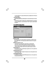
... Panel. If [Power On] is selected, the AC/Power remains off mode. you select [Auto], the onboard HD Audio will enable this option. 3.3.3 ACPI Configuration BIOS SETUP UTILITY Advanced ACPI Configuration Suspend To RAM Restore on AC / Power Loss Ring-In Power On PCI Devices Power On PS / 2 Keyboard Power On...
... Panel. If [Power On] is selected, the AC/Power remains off mode. you select [Auto], the onboard HD Audio will enable this option. 3.3.3 ACPI Configuration BIOS SETUP UTILITY Advanced ACPI Configuration Suspend To RAM Restore on AC / Power Loss Ring-In Power On PCI Devices Power On PS / 2 Keyboard Power On...
User Manual
Page 42
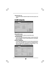
... device connected to the configurations of this option is [non-RAID]. OnBoard IDE Controller Use this item to adjust SATA Operation Mode. BIOS SETUP UTILITY Advanced Primary IDE Master Device Vendor Size LBA Mode Block Mode PIO Mode Async DMA Ultra DMA S.M.A.R.T. IDE Device Configuration You...On Use this item to enable or disable RTC (Real Time Clock) to operate RAID function on the system. 3.3.4 IDE Configuration BIOS SETUP UTILITY Advanced IDE Configuration OnBoard IDE Controller SATA Operation Mode [Both] [non-RAID] To enable or disable the onboard IDE controller.
... device connected to the configurations of this option is [non-RAID]. OnBoard IDE Controller Use this item to adjust SATA Operation Mode. BIOS SETUP UTILITY Advanced Primary IDE Master Device Vendor Size LBA Mode Block Mode PIO Mode Async DMA Ultra DMA S.M.A.R.T. IDE Device Configuration You...On Use this item to enable or disable RTC (Real Time Clock) to operate RAID function on the system. 3.3.4 IDE Configuration BIOS SETUP UTILITY Advanced IDE Configuration OnBoard IDE Controller SATA Operation Mode [Both] [non-RAID] To enable or disable the onboard IDE controller.
User Manual
Page 43
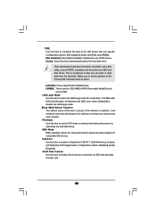
... IDE ARMD (ATAPI Removable Media Device), such as FDISK, to disable the use a disk utility, such as MO. After selecting the hard disk information into BIOS, use of this item to automatically detect the hard disk drive. This is enabled, it will enhance hard disk performance by optimizing the hard disk...
... IDE ARMD (ATAPI Removable Media Device), such as FDISK, to disable the use a disk utility, such as MO. After selecting the hard disk information into BIOS, use of this item to automatically detect the hard disk drive. This is enabled, it will enhance hard disk performance by optimizing the hard disk...
User Manual
Page 44
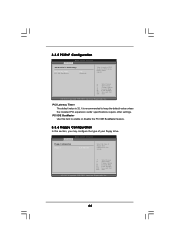
...Select Item Change Option General Help Load Defaults Save and Exit Exit v02.54 (C) Copyright 1985-2003, American Megatrends, Inc. 44 BIOS SETUP UTILITY Advanced Floppy Configuration Floppy A [1.44 MB 312"] Select the type of floppy drive connected to enable or disable the ... The default value is recommended to keep the default value unless the installed PCI expansion cards' specifications require other settings. 3.3.5 PCIPnP Configuration BIOS SETUP UTILITY Advanced Advanced PCI / PnP Settings PCI Latency Timer PCI IDE BusMaster [32] [Enabled] Value in units of your floppy ...
...Select Item Change Option General Help Load Defaults Save and Exit Exit v02.54 (C) Copyright 1985-2003, American Megatrends, Inc. 44 BIOS SETUP UTILITY Advanced Floppy Configuration Floppy A [1.44 MB 312"] Select the type of floppy drive connected to enable or disable the ... The default value is recommended to keep the default value unless the installed PCI expansion cards' specifications require other settings. 3.3.5 PCIPnP Configuration BIOS SETUP UTILITY Advanced Advanced PCI / PnP Settings PCI Latency Timer PCI IDE BusMaster [32] [Enabled] Value in units of your floppy ...


