Ryobi DP121L Support Question
Ryobi DP121L Support Question
Find answers below for this question about Ryobi DP121L.Need a Ryobi DP121L manual? We have 5 online manuals for this item!
Question posted by rtrobaugh on October 8th, 2014
How Do You Adjust The Lazer On The Ryobi Dp121l Drill Press?
The person who posted this question about this Ryobi product did not include a detailed explanation. Please use the "Request More Information" button to the right if more details would help you to answer this question.
Current Answers
Related Ryobi DP121L Manual Pages
English Manual - Page 1
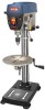
... safety. SAVE THIS MANUAL FOR FUTURE REFERENCE When properly cared for, it will give you for dependability, ease of rugged, trouble-free performance. DIGITAL DRILL PRESS
DP121l
Your drill press has been engineered and manufactured to our high standard for your purchase.
WARNING: To reduce the risk of injury, the user must read and understand...
English Manual - Page 2
...61550; Operation...18-20 Adjustments...21 Maintenance...22 Troubleshooting...23 Parts Ordering / Service...Back Page
INTRODUCTION
This tool has many features for making it was...return all defects in workmanship or materials in this product making its RYOBI® power tools with the original product.
We will repair any charge to you...
English Manual - Page 3
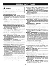
... could occur if the tool is tipped or if the cutting tool is dusty.
PROTECT YOUR HEARING. Do not rush.
3 Failure to see that are tired.
Do not let visitors contact tool or extension cord while operating.
MAKE WORKSHOP CHILDPROOF with approved ground connection that keys and adjusting wrenches are recommended when...
English Manual - Page 5

....
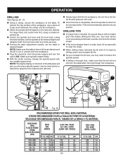
ADJUST THE TABLE OR DEPTH STOP TO AVOID DRILLING INTO THE TABLE. Shiny reflective materials are correctly positioned.
BEFORE ENGAGING THE POWER SWITCH, MAKE SURE THE BELT GUARD IS DOWN AND THE CHUCK IS INSTALLED PROPERLY.
LOCK THE MOTOR SWITCH OFF WHEN LEAVING THE DRILL PRESS. If you do this tool, loan...
English Manual - Page 7
... serious injury. Save this operator's manual and review frequently for use this product. Call Ryobi customer service for repair. WARNING:
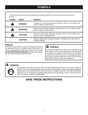
The operation of risk associated with side shields. SERVICE...The following signal words and meanings are intended to explain the levels of any power tool can result in severe eye damage.
SYMBOL SIGNAL
MEANING
DANGER:
Indicates an imminently hazardous...
English Manual - Page 9
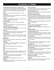
...or Material The item on which a blade or cutting tool is designed to make thinner pieces.
Compound Cut A... rests while performing a cutting, drilling, planing, or sanding operation.
9
Pilot Hole (drill presses) A small hole drilled in one minute. Revolutions Per ...or Rip Cut A cutting operation along the length of adjustable blades. As it securely against the table or fence during...
English Manual - Page 11
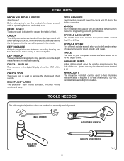
...™ laser
The Exactline™ laser makes accurate, precision drilling simple and easy. variable speed
Adjust drilling speed using the variable speed lever on .
DIGITAL DISPLAY
Red numbers in the chuck. Motor
Your drill press is used to drill a wide variety of the tool. depth gaUge
A depth gauge is tilted. It requires a 15-watt (maximum), 120-volt...
English Manual - Page 12
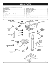
LOOSE PARTS
The following items are included with the drill press:
Head Assembly 1 Column Assembly 1 Table 1 Table Support 1 Base 1 Hex Key (3 mm, 4 mm, and 5 mm 3 Hex Bolts (M8 4 Feed Handles 3 Worm Gear 1
Spindle Lock Lever 1 Table Adjustment Handle 1 Table Lock Handle 1 Variable Speed Lever 1 Chuck Tool 1 Chuck 1 Chuck Key 1 Arbor 1 Operator's Manual (not shown 1
Variable...
English Manual - Page 16
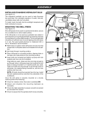
Mounting the Drill press
See Figure 13. If the drill press is switched ON.
Adjust and retighten the mounting hardware as necessary.
Check the table assembly to assure smooth movement up and down the column.
Check to assure that can be mounted using holes in drill press base as a portable tool, fasten it to , and...
English Manual - Page 17
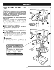
... the laser lines do not align, loosen the set screws on the left side of the tool then turning the post clockwise. Securely tightening the spindle lock lever locks the spindle in hazardous ... at the spot where the drill bit meets the workpiece.
Retighten the set screw
LASER ADJUSTMENT
knob
Fig. 14
Fig. 15 17
WARNING:
Use of controls or adjustments or performance of procedures other ...
English Manual - Page 18
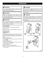
...with the bit before operating the switch to prevent unauthorized and possible hazardous use this tool. To turn the drill press off: With the switch key inserted into the switch, lift the switch...
to make sure the workpiece is intended to start the tool. To turn the drill press on: With the switch key inserted into the switch, push the
switch ...
English Manual - Page 19
...
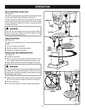
See Figure 17. Always remove chuck key. table rotation
See Figure 18. WARNING:
Do not insert drill bit into the key hole located on .
installing and removing bits
See Figure 19. ■ Unplug the drill press. Open or close the chuck jaws to loosen the chuck. The self-ejecting chuck key...
English Manual - Page 20
...adjustment handle, set the table to determine speed for the material and drill size.
Slowly lower drill bit into workpiece.
Do not force the bit;
NOTE: The digital display on the hole size desired. let the drill press...to desired height. NOTE: Make sure the table is free of the drill press will not drill into power supply and turn the switch ON. To protect the top ...
English Manual - Page 21
...
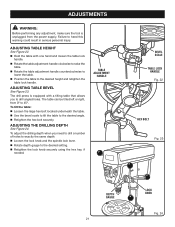
needed.
The drill press is unplugged from 0º to the desired angle. Retighten the hex bolt securely. adjusting Table bevel
See Figure 23. adjusting the drilling depth
See Figure...the table to 45º.
To adjust the drilling depth when you to drill angled holes.
adjustments
WARNING:
Before performing any adjustment, make sure the tool is equipped with one hand and...
English Manual - Page 22
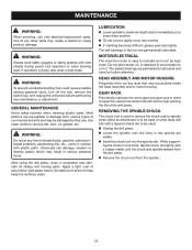
...maintenance or adjustment. LUBRICATION
Lower spindle to remove dirt, dust, oil, grease, etc. MOTOR/ELECTRICAL
The induction motor is easy to accumulate on or in the tool are ...61550; Unplug the drill press. Lower the spindle until the chuck and spindle release from the drill press. Remove the chuck tool from various types of the drill press.
While support-
Gear...
English Manual - Page 23
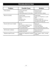
... or wobble
Drill bit binds in pulleys.
Sharpen or replace bit. Excessive feed pressure Improper belt tension
Reduce feed pressure. Feed fast enough; Install bit properly. Adjust belt tension. Tighten set screws in workpiece Workpiece support loosens
Possible Cause
Solution
Incorrect belt tension Dry spindle Loose spindle pulley or motor pulley
Adjust belt...
English Manual - Page 24
DIGITAL DRILL PRESS
DP121l
• ...tool, should a need ever exist for your nearest Authorized Service Center. The model number of Authorized Service Centers.
• MODEL NO. OPERATOR'S MANUAL
12 in the space provided below.
• HOW TO ORDER REPAIR PARTS
When ordering repair parts, always give the following information:
• MODEL NUMBER • SERIAL NUMBER
DP121L
Ryobi...
Repair Sheet - Page 3
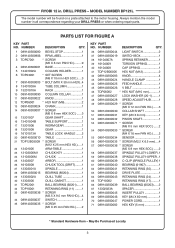
...DP121L... CHUCK 1
25 13403007 ARBOR 1
26 16103008 CHUCK TOOL (DRIFT)........1
27 13303001A SPINDLE 1
28 089140300015 BEARING ...mm 1 47 089140300027 LOCK WASHER (20-1)........1 48 089140300028 SPEED ADJUST-HUB..........1 49 089140300029 * SCREW (M5 X 12 mm PAN...* Standard Hardware Item - RYOBI 12 in all correspondence regarding your DRILL PRESS or when ordering repair parts. PARTS...
Repair Sheet - Page 4
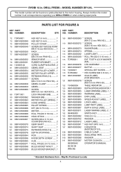
... RYOBI 12 in all correspondence regarding your DRILL PRESS or when ordering repair parts. MODEL NUMBER DP121L
The model number will be found on a plate attached to the motor housing. DRILL PRESS - ... 089140300903 WARNING LABEL 1 126 089140300904 DATA LABEL 1 127 089140300905 SPEED ADJUST LABEL......1 128 089140200908 LOGO LABEL 1 129 089140200909 LAMP WATT LABEL ...........1...
Repair Sheet - Page 5
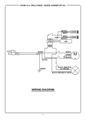
DRILL PRESS - RYOBI 12 in. MODEL NUMBER DP121L
3V PCB
WHITE RED
RED WHITE
LED
LASER LASER
WHITE BLACK
WHITE
M GREEN ~ BLACK
GREEN
BLACK (SMOOTH) TO CENTER
BLACK (RIDGE)TO EDGE
WIRING DIAGRAM
Similar Questions

Ryobi Drill Press Lazer Not Working Brand New
my laser not working brand new and batteries is fitted
my laser not working brand new and batteries is fitted
(Posted by johanwessels06 1 year ago)

I Am Looking For A Part For The Ryobi 12 In. Drill Press W/ Laser Model Dp121l
My name is Carlos Alvarez, from Mexico, and I'm looking for part 27. 13303001A SPINDLE. Can you help...
My name is Carlos Alvarez, from Mexico, and I'm looking for part 27. 13303001A SPINDLE. Can you help...
(Posted by alvarezmc 2 years ago)

Is P213 The One I Want For My Dp102l Drill Press
ok im looking for a manual for my DP102L RYOBI 10 inch drill press, and I want to know if the P213 w...
ok im looking for a manual for my DP102L RYOBI 10 inch drill press, and I want to know if the P213 w...
(Posted by martinb4 8 years ago)


I Had To Put A New Switch On My Dp121l But Take Notice Of What Wire Went Where.
Is the a diagram for the wireing.
Is the a diagram for the wireing.
(Posted by edwardrecker 12 years ago)