
Marantz SR8000 Support Question
Marantz SR8000 Support Question
Find answers below for this question about Marantz SR8000.Need a Marantz SR8000 manual? We have 1 online manual for this item!
Question posted by simonpalmer on November 4th, 2012
How Do I Chnage The Mapping Of A Digital Port From The Front Panel?
The person who posted this question about this Marantz product did not include a detailed explanation. Please use the "Request More Information" button to the right if more details would help you to answer this question.
Current Answers
Related Marantz SR8000 Manual Pages
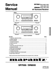
Service Manual - Page 1
...
MULTI
SLEEP
DISPLAY OFF
MUTE
TV
LD
DVD
VCR1
DSS/VCR2
AUX
CDR/MD
TAPE
CD
TUNER
S-VIDEO
AUX INPUT
VIDEO
L AUDIO R
SR8000
AV SURROUND RECEIVER SR8000 SURROUND
CLEAR
MEMORY
TUNING/PRESET
DIGITAL
DOLBY DIGITAL
SURROUND
VOLUME
L
C
R
LFE
LS S RS
PEAK
DOWN
UP
F/P
MODE
STANDBY
POWER ON/STANDBY
PHONES
6ch INPUT
A/D
S-DIRECT
MULTI
SLEEP
DISPLAY OFF...
Service Manual - Page 2
...NOT connected to AC mains and its Power switch ON ), and the face or Front Panel of difficulties, do not hesitate to our National Marantz Subsidiary or Agent. ORDERING PARTS ...OAK CIRCLE, SUITE A AURORA, ILLINOIS 60504 USA PHONE : 630 - 820 - 4800 FAX : 630 - 820 - 8103
AUSTRALIA
TECHNICAL AUDIO GROUP PTY, LTD 558 DARLING STREET, BALMAIN, NSW 2041, AUSTRALIA PHONE : 61 - 2 - 9810 - 5300 FAX : 61 ...
Service Manual - Page 3
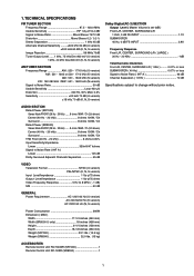
AUDIO SECTION Rated Power (SR7000) Stereo Mode FRONT (20 Hz - 20 kHz) ..... 8 ohms 100W / Ch (2ch driven) Center (40 Hz - 20 kHz 8 ohms 100W / Ch Surround 8 ohms 100W / Ch Rated Power (SR8000) Stereo Mode .... 0.5% Selectivity 20 kHz 70 dB (U version) ±18 kHz 70 dB (K, N, S version)
Dolby Digital(AC-3) SECTION Output Level ( Master Volume is set 0dB ) Front L/R, CENTER, SURROUND L/R 1 KHz, 0...
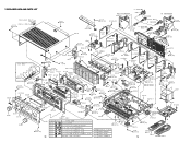
Service Manual - Page 4
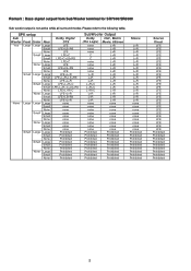
Remark : Bass signal output from Sub Woofer terminal for SR7000/SR8000
Sub woofer output is not active while all surround modes.
Please refer to the following table. SPK ... Large Small None Large Small None Large Small None Large Small None Large Small None Large Small None Large Small None
Dolby Digital DTS
LFE LFE+LS+RS
LFE LFE+C LFE+C+LS+RS LFE+C
LFE LFE+LS+RS
LFE LFE+L+R LFE+L+R+LS+RS LFE...
Service Manual - Page 6
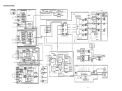
... ON/OFF CONTROL VOL CONTROL MUTE CONTROL CROSS OVER CONTROL POWER DOUN STANDBY CONTROL
5VL FL
24V VKK
+/- 3. CONTROL
V-AUDIO
PS54
TV LD DVD IN VCR1 OUT IN DSS/VCR2 OUT
INPUT SEL.
SR8000 ONLY
6dB
NJM2267 (2/2)
OSD LC74781
OSD LC74781
DRV NJM2244
TV Y C
LD
Y C
DVD Y C
VCR1
IN Y C
OUT Y C
IN Y C
DSS/VCR2...
Service Manual - Page 9
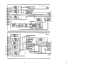
... 22 21 20 19 18 17 16
LC7536 1 2 3 4 5 6 7 8 9 10 11 12 13 14 15
Audio selector(Audio) P.C.Board
PS04
RRJ-*S**
RRM-*S5*
CS63 4.7/50V
-15V -15V-3
RS81 0
CS65 4.7/50V
RS73 100K
RS74 100K CS64 4.7/50V...15V-12
CQ54 100/16V
JQ04 12MQ-ST-L TO JY05(PY04)
1 TUNER-L(IN) 2 TUNER-R(IN) 3 GND 4 AUDIO-R(IN/OUT) 5 AUDIO-L(IN/OUT) 6 GND 7 MULTI-L(OUT) 8 MULTI-R(OUT) 9 GND 10 CDR-OUT-L(OUT) 11 CDR-OUT-R(OUT)...
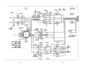
Service Manual - Page 12

...
2
1
QC03 NJM2068M
RC17 100K
VSS
-
+15VE
+
15V-2
+ - VCC
5
678
CC12 10/50V
A2
RC18 100K
CC25 0.01
CENTER
6CH SW
A2
PG04
6ch/Preout P.C.Board
SR8000
RC12 22K RC06 27K CC40 47P CH
2CH/DSP/6CH SELECTOR
CC17 22/50V
DSP CENT 6CH CENT CENT
SL
FL
6CH SL
6CH FL...
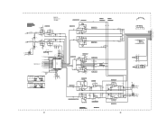
Service Manual - Page 16
...
1
CJ02 10/50V
RJ06 2.2K
RJ10 2.2K
3
+
4
CJ06 M 1000P
-15VAD -15V-37
SURR. P604-2/2
DSP P.C.Board
SR8000
1kHz,0dB=1.886V
+5VAA 5V-26
AL
AR
_ATT
-15V-37 -15VAD
RDA-*K**
RK23 RK25 0 5.6K
LT
RK29 4.7K RK24 RK26...CWDA ADDATA
FS96 _CWDA
RK20 0
INPUT:ANALOG SDWCK=48kHz
SDBCK=3.07MHz MCLK=12.288MHz
INPUT:DIGITAL SDWCK=48kHz SDBCK=64FS MCLK=256FS
ADCAL
D6
CK22 470P 50V
D6
SDOS OCKS M/_S...
Service Manual - Page 17
...
11 12
DEM1 DEM0 MCKO DVDD DVSS _PD XTS ICKS1 ICKS0 CAD1 CAD0 22 23
INPUT:ANALOG SDWCK=48kHz
SDBCK=3.07MHz MCLK=12.288MHz
INPUT:DIGITAL SDWCK=48kHz SDBCK=64FS MCLK=256FS
ADCAL
D6
CK22 470P 50V
D6
CD08 0.1 16V
CD09 100/10V
LD01 *
D6
RK22 22
A1 0V-8
+5VD 5V...
Service Manual - Page 27

... port for general purpose (Refer to " IPORT Register")
98 IPORT1 I + Input port for more than 1024 LR Clock Cycles. Connect to impose a 50ms/15 ms response characteristic on the output audio...clock mode as either 256, 384 or 512 FS . Voltage Reference Filter Capacitor Connection. Connect to digital +5 V supply. Mute. Q351:LC72722 48 Ground
61 RAMA4 O External SRAM Interface address 4
...
Service Manual - Page 28

...DIF1 I Audio Data Interface Format Pin in parallel mode
CCLK I Control Data Clock Pin in serial mode
43 LOOP0 l Loop-back Mode Pin in parallel mode
I Enables digital loop-... MCLK12 ORed with serial control register if P/S="L"
14 MCKO O Master Clock Output Pin
15 DVDD
Digital Power Supply Pin
16 DVSS
Digital Ground Pin
17 PD
I Power-Down & Reset Pin
When "L", the AK4526 is powered-down ...
Service Manual - Page 29

...select - SPDIF output select - Digital/ _Analog select - Analog / ...Audio Serial Port
R e g i s t e r s
11 FSYNC
12 SCK
26 SDATA
1 C
14 U
28 VERF
15 CBL
25 ERF
C 1
CS d/FREQ REPORT 1 Cd/F1 2
CS c/FREQ REPORT 0 Cc/F0 3
CS b/ERROR CONDITION 2 Cb/E2 4
CS a/ERROR CONDITION 1 Ca/E1 5
CS 0/ERROR CONDITION 0 C0/E0 6
DIGITAL POWER
VD+ 7
DIGITAL GROUND DGND 8
RECEIVE POSITIVE
RXP 9
RECEIVE...
Service Manual - Page 30
... OC K WA S HE RS
009G
5128 3 X8 ( U)
5126 4 X8 ( U)
x5
MARK MAT ERI AL / F I ON W0 0 1
905G
SR8000 ONLY
5127 3 X8 ( M)
5127 3 X 8 ( M)
5127 3 X8 ( M)
L B0 1
DSP/ DT S
PU8 4 , PU9 4
5128 3...X 8 ( M)
5128 3 X 8 ( M)
014G 5150 3 X 6 ( M)
002G
901G
PL 0 4 CVBS
5128 3 X1 6 ( M)
x7
PS5 4 AUDIO . 2
PS0 4 AUDIO. 1
5127 3 X8 ( M)
5110 3 X 6 ( M)
5128 3 X 8 ( M)
0 0 1 K, 0 0 2 K 0 0 3 K, 0 0...
Service Manual - Page 31
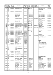
.../U1B
001B 7000 /U1G
996500003422 FRONT AL PANEL BLACK
996500003436 FRONT AL PANEL GOLD
FRONT AL PANEL STANDBY BLACK FRONT AL PANEL STNDBY GOLD
320J248010 320J248110 320J248020 320J248120
001B 8000 ... 7000/U
996500003434
PACKING USER GUIDE SR7000 USER GUIDE SR7000 USER GUIDE SR7000 USER GUIDE SR8000 USER GUIDE SR8000 USER GUIDE SR8000
Z001 7000
Z001 8000
Z007 /K 1
Z007 /K 2
Z007 /N 1
Z007 /N...
Service Manual - Page 33
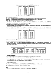
...Large Large Large
SPK setup
Center
Surr. Fig 2. Input selection order by using analog stereo signal or PCM audio signal. When FLD shows "ALL CH D1"(Refer to "3. Input and output test mode"), the Cross Over...to output the same signal from 5 channels, even though 2 channels audio signal comes in page3 of AMP function for SPK setup.
1. When the product is available to 2 channels PCM...
Service Manual - Page 35

... output to transmission *loop antenna. (*:Standard required loop)
999 kHz (K, S, N) 1000 kHz
(U)
Level 300 µV/m (50dB/m) Mod. 400 Hz 30%
Tuning point
LA06
REMARK: For receiving antenna, the adapted one is available. AM (MW) Tracking Adjustment
Output level (L or R)
Maximum at TAPE-OUT
1404 kHz
2
(K, S, N) Level 300 µV/m (50dB/m)
1400 kHz...
Service Manual - Page 38
...or SPK Relay has problem
(Volume, & Power Amp are OK)
PS04,PS54(Audio In) orP604 (QK04:ADC)has any problem
(Volume , Power Amp &
Audio Input are
OK ?
yes
no
Analog S-Direct are OK) QK04,Q601(P604)
...problem
Volume, HDAM, QC04 or Preout Relay has any problem.(PG04)
No sound from SPK on PCM STEREO(Digital In)
Pre output is no OK ?
no DSP (Q601) has any trouble
(DAC is no
S-Direct...
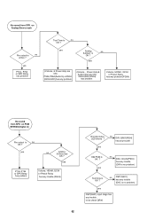
Service Manual - Page 39
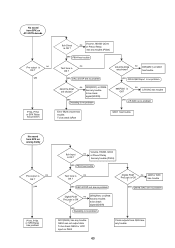
...,PCM are shown?
no DIR(QR01) or Q601 has trouble
yes DIR & Q601input is no problem
Digital PCM ProLogic is
OK ? To be check QK04 or Lt/Rt input on analog Dolby
Pre output is...Relay has problem
6ch Direct is OK ?
to be check
signal(SDIDR)
yes
Decoding is no problem
Digital PCM ProLogic is
no
OK ?
to be check
signal(SDIDR)
yes
Decoding is no problem
96kPCM ...
Service Manual - Page 40
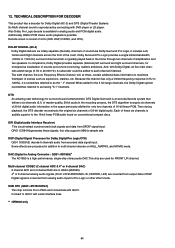
....When added to the 5 full range channels, the Dolby Digital system issometimes referred to QU01 with QU01.
Connect to as explosions, crashes, etc. DIR (Digital audio Interface Receiver) This circuit extract synchronized clock signals and data from analog audio input for Dolby Digital (AC-3) and DTS (Digital Theater System). SUB CPU (Q691:uPD78018FGC) This chip controls ICs...
Service Manual - Page 41
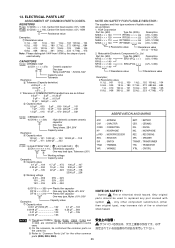
..., be used actually. CAP. HP µ-PRO RES. VAR.
: ANTENNA : CAPACITOR : CONNECTING : HEADPHONE : MICROPROCESSOR : RESISTOR : SWITCH : TRIMMING : VARIABLE
BATT. : BATTERY CER. : CERAMIC DIG. : DIGITAL MIC. : MICROPHONE REC. : RECORDING SPK : SPEAKER TRANSF. : TRANSFORMER TRS. : TRAMSISTOR X'TAL : CRYSTAL
6) DF15 × × × 350
Plastic film capacitor
DF15 × × ×...
Similar Questions

How To Connect To Tv And Speakers From Maranta 4300 Receiver
(Posted by nestorbalbin52 7 months ago)

I Select Cd/dvd Output No Sound.what Happen?how To Repair That?
(Posted by tienlunwu100 4 years ago)

Digital Recorder
I am a dentist that goes to a lot of post-graduate lectures. Would you please suggest an excellent d...
I am a dentist that goes to a lot of post-graduate lectures. Would you please suggest an excellent d...
(Posted by Boytch1984 9 years ago)

Marantz Sr4200...digital 1 & 2
I am trying to hook up a playstation3 to the receiver (into Digital 1)..I can't find diital 1 (or 2 ...
I am trying to hook up a playstation3 to the receiver (into Digital 1)..I can't find diital 1 (or 2 ...
(Posted by hankscompany 10 years ago)

How Do You Switch Tuner To Digital Mode From Analog?
(Posted by Timcunningham 11 years ago)