
Service Manual
Page 1
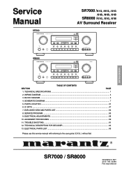
.../MD TAPE CD TUNER S-VIDEO AUX INPUT VIDEO L AUDIO R SR8000 AV SURROUND RECEIVER SR8000 SURROUND CLEAR MEMORY TUNING/PRESET DIGITAL DOLBY DIGITAL SURROUND VOLUME L C R LFE LS S RS PEAK DOWN UP F/P MODE STANDBY POWER ON/STANDBY PHONES 6ch INPUT A/D S-DIRECT MULTI SLEEP DISPLAY OFF MUTE TV LD DVD VCR1 DSS/VCR2 AUX CDR/MD TAPE CD TUNER S-VIDEO AUX INPUT VIDEO L AUDIO R TABLE OF CONTENTS SECTION PAGE 1. BLOCK DIAGRAM ...5 4. IC DATA ...47 7. TECHNICAL DESCRIPTION FOR DECODER 64 13. ELECTRICAL PARTS LIST ...65 Please use this service manual...
.../MD TAPE CD TUNER S-VIDEO AUX INPUT VIDEO L AUDIO R SR8000 AV SURROUND RECEIVER SR8000 SURROUND CLEAR MEMORY TUNING/PRESET DIGITAL DOLBY DIGITAL SURROUND VOLUME L C R LFE LS S RS PEAK DOWN UP F/P MODE STANDBY POWER ON/STANDBY PHONES 6ch INPUT A/D S-DIRECT MULTI SLEEP DISPLAY OFF MUTE TV LD DVD VCR1 DSS/VCR2 AUX CDR/MD TAPE CD TUNER S-VIDEO AUX INPUT VIDEO L AUDIO R TABLE OF CONTENTS SECTION PAGE 1. BLOCK DIAGRAM ...5 4. IC DATA ...47 7. TECHNICAL DESCRIPTION FOR DECODER 64 13. ELECTRICAL PARTS LIST ...65 Please use this service manual...
Service Manual
Page 2
...parts 4. Complete address 2. CHOME, SAGAMIONO SAGAMIHARA - ORDERING PARTS : Parts can insure that your MARANTZ product will be ordered either primary AC cord connector pins ( with unit NOT connected to be repaired or corrected before AC power is applied, and verified before it is return to eliminate delays in stereo sound... TAIWAN R.O.C. Only original MARANTZ parts can be considered as null and void. Way of product and controls and chassis bottom. Ref. MARANTZ DESIGN AND SERVICE Using superior design and selected high grade components, MARANTZ company has created the ...
...parts 4. Complete address 2. CHOME, SAGAMIONO SAGAMIHARA - ORDERING PARTS : Parts can insure that your MARANTZ product will be ordered either primary AC cord connector pins ( with unit NOT connected to be repaired or corrected before AC power is applied, and verified before it is return to eliminate delays in stereo sound... TAIWAN R.O.C. Only original MARANTZ parts can be considered as null and void. Way of product and controls and chassis bottom. Ref. MARANTZ DESIGN AND SERVICE Using superior design and selected high grade components, MARANTZ company has created the ...
Service Manual
Page 3
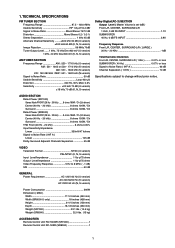
... dB (K, N, S version) Dolby Digital(AC-3) SECTION Output Level ( Master Volume is set 0dB ) Front L/R, CENTER, SURROUND L/R 1 KHz, 0 dB FS INPUT 1.1V SUBWOOFER 40 Hz, 0 dB FS INPUT 3.8V Frequency Response Front L/R, CENTER, SURROUND L/R ( LARGE ) 20 Hz - 20 KHz 1dB Total Harmonic Distortion Front L/R, CENTER, SURROUND L/R ( 1 KHz 0.01% or less SUBWOOFER ( 40 Hz 0.07% or less Signal to Noise Ratio ( IHF-A 96 dB Channel Separation ( 1 KHz 70 dB Specifications subject to 8 MHz...
... dB (K, N, S version) Dolby Digital(AC-3) SECTION Output Level ( Master Volume is set 0dB ) Front L/R, CENTER, SURROUND L/R 1 KHz, 0 dB FS INPUT 1.1V SUBWOOFER 40 Hz, 0 dB FS INPUT 3.8V Frequency Response Front L/R, CENTER, SURROUND L/R ( LARGE ) 20 Hz - 20 KHz 1dB Total Harmonic Distortion Front L/R, CENTER, SURROUND L/R ( 1 KHz 0.01% or less SUBWOOFER ( 40 Hz 0.07% or less Signal to Noise Ratio ( IHF-A 96 dB Channel Separation ( 1 KHz 70 dB Specifications subject to 8 MHz...
Service Manual
Page 4
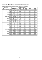
... L+R L+R L+R L+R L+R L+R L+R L+R L+R L+R L+R L+R L+R L+R none none none none none none none none none Prohibited Prohibited Prohibited Prohibited Prohibited Prohibited Prohibited Prohibited Prohibited Source Direct LFE LFE LFE LFE LFE LFE LFE LFE LFE LFE LFE LFE LFE LFE LFE LFE LFE LFE LFE LFE LFE LFE LFE LFE LFE LFE LFE Prohibited Prohibited Prohibited Prohibited Prohibited Prohibited Prohibited Prohibited Prohibited 2 Please refer to the following table. Remark : Bass signal output from Sub Woofer terminal for SR7000/SR8000 Sub woofer output is not active while all surround modes.
... L+R L+R L+R L+R L+R L+R L+R L+R L+R L+R L+R L+R L+R L+R none none none none none none none none none Prohibited Prohibited Prohibited Prohibited Prohibited Prohibited Prohibited Prohibited Prohibited Source Direct LFE LFE LFE LFE LFE LFE LFE LFE LFE LFE LFE LFE LFE LFE LFE LFE LFE LFE LFE LFE LFE LFE LFE LFE LFE LFE LFE Prohibited Prohibited Prohibited Prohibited Prohibited Prohibited Prohibited Prohibited Prohibited 2 Please refer to the following table. Remark : Bass signal output from Sub Woofer terminal for SR7000/SR8000 Sub woofer output is not active while all surround modes.
Service Manual
Page 6
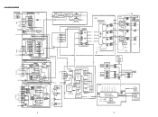
.../6R LT/RT FUNCTION CONTROL 6CH DIRECT IN 6CH DIR/STEREO LC78212 S-DIRECT DSP F L/R 6-CH DSP S L/R 6-CH 6-CH DSP C 6-CH SW DSP FRONT L/R SURR L/R CENTER SUB WOOFER VOL CONTROL MUTE CONTROL MULTI RELAY +15V -15V +5V STEREO CONTROL PRE OUT FRONT P704 MAIN AMP MAIN AMP MAIN AMP PW04 HEADPHONE SPK OUTPUT L G G FRONT R MAIN CENTER AMP CENTER G MAIN SURROUND AMP SUB WOOFER MAIN AMP PROTECTOR DRIVE SPEAKER RELAY CONTROL RELAY CONTROL PY04 PB74 POWER SW (FOR K,N,S) (TV-3) SURROUND L G G R P754 DIG 6 SR8000 ONLY DIG...
.../6R LT/RT FUNCTION CONTROL 6CH DIRECT IN 6CH DIR/STEREO LC78212 S-DIRECT DSP F L/R 6-CH DSP S L/R 6-CH 6-CH DSP C 6-CH SW DSP FRONT L/R SURR L/R CENTER SUB WOOFER VOL CONTROL MUTE CONTROL MULTI RELAY +15V -15V +5V STEREO CONTROL PRE OUT FRONT P704 MAIN AMP MAIN AMP MAIN AMP PW04 HEADPHONE SPK OUTPUT L G G FRONT R MAIN CENTER AMP CENTER G MAIN SURROUND AMP SUB WOOFER MAIN AMP PROTECTOR DRIVE SPEAKER RELAY CONTROL RELAY CONTROL PY04 PB74 POWER SW (FOR K,N,S) (TV-3) SURROUND L G G R P754 DIG 6 SR8000 ONLY DIG...

Service Manual
Page 10
...DVD * * L H H * L L * L H * VCR1 * * * H L * L L * L L L DSS * * L L H * L L * L L H AUX * L H H H * L L L H * * 13 14 CVBS-INPUT Videoo selector(CVBS) P.C.Board PL04 LD CL66 10/50V TV CL61 10/50V RVC-*L** RRL-*L6* RCN-*Y6* +5V 5V-34 14 13 12 11 10 9 8 Q3 Q5 CL62 10/50V VCC Q4 CL85 0.01 GND MM1140 QL61 MM1140 VIDEO SW (MULTI...) TV LD JL01 TV RL01 82 LD DVD JL02 IN VCR1 OUT IN VCR2 JL03 OUT MONITOR RL03 ...2.2/50V SR7000 0 OHM OUT 2.1 SAG QL03-1 NJM2267 CL53 22P CH 1.8 RL31 100 CL75 100/10V SR8000 ONLY MULTI OSD CONTROL DL62 DL63 DAN202K ...
...DVD * * L H H * L L * L H * VCR1 * * * H L * L L * L L L DSS * * L L H * L L * L L H AUX * L H H H * L L L H * * 13 14 CVBS-INPUT Videoo selector(CVBS) P.C.Board PL04 LD CL66 10/50V TV CL61 10/50V RVC-*L** RRL-*L6* RCN-*Y6* +5V 5V-34 14 13 12 11 10 9 8 Q3 Q5 CL62 10/50V VCC Q4 CL85 0.01 GND MM1140 QL61 MM1140 VIDEO SW (MULTI...) TV LD JL01 TV RL01 82 LD DVD JL02 IN VCR1 OUT IN VCR2 JL03 OUT MONITOR RL03 ...2.2/50V SR7000 0 OHM OUT 2.1 SAG QL03-1 NJM2267 CL53 22P CH 1.8 RL31 100 CL75 100/10V SR8000 ONLY MULTI OSD CONTROL DL62 DL63 DAN202K ...

Service Manual
Page 27
... Channel Zero Flag Output. Analog Ground. Analog Power Supply. Must run continuously; Ground - +3.3V power supply (for PLL circuit) I AC-3/DTS bitstream (or PCM) data input for SDOA, SDIB, SDOB. (Refer to the default values. NAME I + Word clock input for Main DSP (Refer to AGND. Used for input data. Digital de-emphasis is enabled when this signal. Selects 48 kHz (LO) or 96 kHz Sample Frequency Control. Filter Capacitor connection, connect...
... Channel Zero Flag Output. Analog Ground. Analog Power Supply. Must run continuously; Ground - +3.3V power supply (for PLL circuit) I AC-3/DTS bitstream (or PCM) data input for SDOA, SDIB, SDOB. (Refer to the default values. NAME I + Word clock input for Main DSP (Refer to AGND. Used for input data. Digital de-emphasis is enabled when this signal. Selects 48 kHz (LO) or 96 kHz Sample Frequency Control. Filter Capacitor connection, connect...

Service Manual
Page 28
... Clock Frequency Select Pin L: MCLK, "H" MCLK12 ORed with serial control register if P/S="L" 14 MCKO O Master Clock Output Pin 15 DVDD Digital Power Supply Pin 16 DVSS Digital Ground Pin 17 PD I Power-Down & Reset Pin When "L", the AK4526 is powered-down . Pin Narne I Lch Analog Positive Input pin 31 RlN- "H": Master mode 4 BICK I/O Audio Serial Data Clock Pin 5 LRCK l/O Input/Output Channel Clock Pin 6 SDTI1 I DAC1 Audio Serial Data Input Pin...
... Clock Frequency Select Pin L: MCLK, "H" MCLK12 ORed with serial control register if P/S="L" 14 MCKO O Master Clock Output Pin 15 DVDD Digital Power Supply Pin 16 DVSS Digital Ground Pin 17 PD I Power-Down & Reset Pin When "L", the AK4526 is powered-down . Pin Narne I Lch Analog Positive Input pin 31 RlN- "H": Master mode 4 BICK I/O Audio Serial Data Clock Pin 5 LRCK l/O Input/Output Channel Clock Pin 6 SDTI1 I DAC1 Audio Serial Data Input Pin...

Service Manual
Page 29
... I - I /F DO L Power OFF output L Power Down - I /F YSS912 - DIR Status - SPDIF input select - SPDIF input select - SPDIF output select - Analog / _Digital select - I - I Avss - I -- I AN POWER_DETECT0 I AN POWER_DETECT1 I AN KEY_INPUT0 I AN KEY_INPUT1 I /F CLK L Surr. Mono L LFE L Peak pull up pull up pull up - Vol. Pulse Encoder - Pulse Encoder L Y/C Video Detector L Multi Video Detector L Head Phone Switch - I AN KEY_INPUT2 Act. I /F YSS912 (sub DSP) - Key Input 0 - n.c. DIR Status - H Fs=96k set H Bypass DSP...
... I - I /F DO L Power OFF output L Power Down - I /F YSS912 - DIR Status - SPDIF input select - SPDIF input select - SPDIF output select - Analog / _Digital select - I - I Avss - I -- I AN POWER_DETECT0 I AN POWER_DETECT1 I AN KEY_INPUT0 I AN KEY_INPUT1 I /F CLK L Surr. Mono L LFE L Peak pull up pull up pull up - Vol. Pulse Encoder - Pulse Encoder L Y/C Video Detector L Multi Video Detector L Head Phone Switch - I AN KEY_INPUT2 Act. I /F YSS912 (sub DSP) - Key Input 0 - n.c. DIR Status - H Fs=96k set H Bypass DSP...
Service Manual
Page 31
... MASTER GOLD 312J154020 LENS IR BLACK 275W355010 LENS IR GOLD 275W355110 MASK IR 312J303030 LENS STANDBY LENS 312J355010 JOINT POWER 312J125010 BUTTON POWER SW BLACK 255W270010 BUTTON POWER SW GOLD 255W270110 BUTTON POWER SW TACT 320J270040 BLACK BUTTON POWER SW TACT 320J270140 GOLD 009G 010G 915G /U 482246242129 LEG FRONT SIDE 482246242048 LEG REAR SIDE BUSHING AC CORD 183J057010 183J057110 450H259010 J001 /K,/N,/S 482226731964 JACK...
... MASTER GOLD 312J154020 LENS IR BLACK 275W355010 LENS IR GOLD 275W355110 MASK IR 312J303030 LENS STANDBY LENS 312J355010 JOINT POWER 312J125010 BUTTON POWER SW BLACK 255W270010 BUTTON POWER SW GOLD 255W270110 BUTTON POWER SW TACT 320J270040 BLACK BUTTON POWER SW TACT 320J270140 GOLD 009G 010G 915G /U 482246242129 LEG FRONT SIDE 482246242048 LEG REAR SIDE BUSHING AC CORD 183J057010 183J057110 450H259010 J001 /K,/N,/S 482226731964 JACK...
Service Manual
Page 32
... -- Input selection mode (without setting to system setup menu) This mode is available to select the input without using system setup menu) 5 or 6 channels output mode (This mode is changed in the following steps. 1. By pressing both [ MEMO ] and [ MODE ] buttons simultaneously each time as shown in Fig 2. ( [ MODE ] button is available for the functions as follows. When FLD shows "AUTO D1"( Refer to "3. 8. Input and output test mode This mode is in Fig 1 by the following steps. 1. SERVICE PROGRAM...
... -- Input selection mode (without setting to system setup menu) This mode is available to select the input without using system setup menu) 5 or 6 channels output mode (This mode is changed in the following steps. 1. By pressing both [ MEMO ] and [ MODE ] buttons simultaneously each time as shown in Fig 2. ( [ MODE ] button is available for the functions as follows. When FLD shows "AUTO D1"( Refer to "3. 8. Input and output test mode This mode is in Fig 1 by the following steps. 1. SERVICE PROGRAM...
Service Manual
Page 33
... Large Subwoofer ON OFF OFF 4. FLD shows "DEFAULT" for RC-18SR*) 2. AC-3 or DTS source is not necessary to work the muting transistor only by using analog stereo signal or PCM audio signal. But, Left channel and Right channel of AMP function for remote commander only. 2. SPK set up mode Button for RC-18SR [ CH+ ] [ LVL+ ] [ LVL- ] INDICATION for analog input. Note * : The remote controller RC2000mkII is POWER ON, press both [ CLEAR ] and [ DISPLAY OFF ] buttons simultaneously. Input selection...
... Large Subwoofer ON OFF OFF 4. FLD shows "DEFAULT" for RC-18SR*) 2. AC-3 or DTS source is not necessary to work the muting transistor only by using analog stereo signal or PCM audio signal. But, Left channel and Right channel of AMP function for remote commander only. 2. SPK set up mode Button for RC-18SR [ CH+ ] [ LVL+ ] [ LVL- ] INDICATION for analog input. Note * : The remote controller RC2000mkII is POWER ON, press both [ CLEAR ] and [ DISPLAY OFF ] buttons simultaneously. Input selection...

Service Manual
Page 34
... table for adjustment vaule Time since power on after 4 minutes Channel Front L Center Front R Surr. R Adjustment Point R767 RT67 R768 RP67 RT68 Test Point Speaker Output Terminal Adjustment Vaule ± 20mV Note : If the measured value is not exceed ±50mV, no need to adjust the DC offset. 2. L Surr. ELECTRICAL ADJUSTMENTS 1. DC offset adjustment Master Volume : Minimum, Speaker out : non Load Step 1 Power on Channel Front L Center Front...
... table for adjustment vaule Time since power on after 4 minutes Channel Front L Center Front R Surr. R Adjustment Point R767 RT67 R768 RP67 RT68 Test Point Speaker Output Terminal Adjustment Vaule ± 20mV Note : If the measured value is not exceed ±50mV, no need to adjust the DC offset. 2. L Surr. ELECTRICAL ADJUSTMENTS 1. DC offset adjustment Master Volume : Minimum, Speaker out : non Load Step 1 Power on Channel Front L Center Front...

Service Manual
Page 35
...is preset by the original supplier. AM (LW) Tracking Adjustment [N version] Step **Input Signal Source Signal Connection Frequency Source Signal Output Level and Modulation Reception Adjustment Adjustment Frequency Point Value Signal generator output to 1 transmission *loop antenna. 171 kHz (*:Standard required loop) Level 500 µV/m (54dB/m) Mod. 400 Hz 30% 171 kHz LA03 Output level (L or R) Maximum at TAPE-OUT 3. FM MONO. AM (MW) Tracking Adjustment Output level (L or R) Maximum at TAPE-OUT Step **Input Signal Source Signal Connection Frequency Source Signal...
...is preset by the original supplier. AM (LW) Tracking Adjustment [N version] Step **Input Signal Source Signal Connection Frequency Source Signal Output Level and Modulation Reception Adjustment Adjustment Frequency Point Value Signal generator output to 1 transmission *loop antenna. 171 kHz (*:Standard required loop) Level 500 µV/m (54dB/m) Mod. 400 Hz 30% 171 kHz LA03 Output level (L or R) Maximum at TAPE-OUT 3. FM MONO. AM (MW) Tracking Adjustment Output level (L or R) Maximum at TAPE-OUT Step **Input Signal Source Signal Connection Frequency Source Signal...

Service Manual
Page 36
... L channel with the RF signal modulated only L channel first and confirm the R channel with the RF signal modulated only R channel. Reception Adjustment Adjustment Frequency Point Value 98 MHz (P2) R211 Output level Minimum at TAPE-OUT R channel same specification as Output level 2 98 MHz FM STEREO distortion adjustment. 98 MHz (P2) R211 Similar as FM STEREO distortion adjustment. R channel 60 FM STEREO Separation Adjustment Step Input Signal Source Connection Signal Frequency 1 Signal generator output to the "TUNED" indicate point. FM Muting Level Adjustment Turn...
... L channel with the RF signal modulated only L channel first and confirm the R channel with the RF signal modulated only R channel. Reception Adjustment Adjustment Frequency Point Value 98 MHz (P2) R211 Output level Minimum at TAPE-OUT R channel same specification as Output level 2 98 MHz FM STEREO distortion adjustment. 98 MHz (P2) R211 Similar as FM STEREO distortion adjustment. R channel 60 FM STEREO Separation Adjustment Step Input Signal Source Connection Signal Frequency 1 Signal generator output to the "TUNED" indicate point. FM Muting Level Adjustment Turn...
Service Manual
Page 37
... OSD menu is too Low. standby mode To be ckeck CV-DET, Y/C-DET 61 yes FLD shows no supply +24V ? yes Can PY04 no to PU04? yes PB04 , or connection has any problem PY04,or Main Transf(L001) has any trouble. yes Vkk or FL is OK ? yes Supply +15V no to PU04? Video input detection has any problem No picture from Monitor output...
... OSD menu is too Low. standby mode To be ckeck CV-DET, Y/C-DET 61 yes FLD shows no supply +24V ? yes Can PY04 no to PU04? yes PB04 , or connection has any problem PY04,or Main Transf(L001) has any trouble. yes Vkk or FL is OK ? yes Supply +15V no to PU04? Video input detection has any problem No picture from Monitor output...
Service Manual
Page 38
... any trouble (DIR is no problem) Test tone is OK ? yes P704, P754 or SPK Relay has problem (Volume, & Power Amp are OK) PS04,PS54(Audio In) orP604 (QK04:ADC)has any problem (Volume , Power Amp & Audio Input are OK ? to be check QR06 No sound from SPK on Analog Stereo mode Test Tone is no OK ? no problem) yes DSP(Q601) input stage has any problem.(PG04) No sound from SPK on PCM STEREO(Digital In) Pre output is...
... any trouble (DIR is no problem) Test tone is OK ? yes P704, P754 or SPK Relay has problem (Volume, & Power Amp are OK) PS04,PS54(Audio In) orP604 (QK04:ADC)has any problem (Volume , Power Amp & Audio Input are OK ? to be check QR06 No sound from SPK on Analog Stereo mode Test Tone is no OK ? no problem) yes DSP(Q601) input stage has any problem.(PG04) No sound from SPK on PCM STEREO(Digital In) Pre output is...
Service Manual
Page 39
... problem DD,DTS,PCM are no problem ADC(QK04) has any trouble 63 No sound from QK04 are shown? QK04 can not output data To be check signal(SDIDR) yes Decoding is no problem Digital PCM ProLogic is OK ? No sound from SPK on analog Dolby Pre output is no OK ? yes P704, P754 or SPK Relay has problem 6ch Direct is no or Preout Relay has any trouble. Volume...
... problem DD,DTS,PCM are no problem ADC(QK04) has any trouble 63 No sound from QK04 are shown? QK04 can not output data To be check signal(SDIDR) yes Decoding is no problem Digital PCM ProLogic is OK ? No sound from SPK on analog Dolby Pre output is no OK ? yes P704, P754 or SPK Relay has problem 6ch Direct is no or Preout Relay has any trouble. Volume...
Service Manual
Page 40
... speakers. The sixth channel, the Low Frequency Effects Channel, will, at times, contain additional bass information to the 16-bit linear PCM audio found on HALL, MATRIX, and MOVIE mode. Each of DSP. DSP (Digital Signal Processor for Dolby Digital/Pro Logic/DTS) Q601 (YSS912) decode 6 channels audio from SPDIF signal input. Decode circuit is reproduced by connecting with DVD player or LD player. In comparison, Dolby Digital provides separate (discrete) left surround and right surround channels...
... speakers. The sixth channel, the Low Frequency Effects Channel, will, at times, contain additional bass information to the 16-bit linear PCM audio found on HALL, MATRIX, and MOVIE mode. Each of DSP. DSP (Digital Signal Processor for Dolby Digital/Pro Logic/DTS) Q601 (YSS912) decode 6 channels audio from SPDIF signal input. Decode circuit is reproduced by connecting with DVD player or LD player. In comparison, Dolby Digital provides separate (discrete) left surround and right surround channels...
Service Manual
Page 41
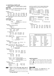
...component substitution (other common parts (RI05, DD4, DK4). 65 ELECTRICAL PARTS LIST ASSIGNMENT OF COMMON PARTS CODES. Only original parts should be confirmed the common parts on the parts list. 3) Refer to replaced any part marked with symbol . NOTE : 1) The above CODES... (0.1 Ω − 10 kΩ) 2. VAR. : ANTENNA : CAPACITOR : CONNECTING : HEADPHONE : MICROPROCESSOR : RESISTOR : SWITCH : TRIMMING : VARIABLE BATT. : BATTERY CER. : CERAMIC DIG. : DIGITAL MIC. : MICROPHONE REC. : RECORDING SPK : SPEAKER TRANSF. : TRANSFORMER TRS. : TRAMSISTOR X'TAL : CRYSTAL 6) DF15...
...component substitution (other common parts (RI05, DD4, DK4). 65 ELECTRICAL PARTS LIST ASSIGNMENT OF COMMON PARTS CODES. Only original parts should be confirmed the common parts on the parts list. 3) Refer to replaced any part marked with symbol . NOTE : 1) The above CODES... (0.1 Ω − 10 kΩ) 2. VAR. : ANTENNA : CAPACITOR : CONNECTING : HEADPHONE : MICROPROCESSOR : RESISTOR : SWITCH : TRIMMING : VARIABLE BATT. : BATTERY CER. : CERAMIC DIG. : DIGITAL MIC. : MICROPHONE REC. : RECORDING SPK : SPEAKER TRANSF. : TRANSFORMER TRS. : TRAMSISTOR X'TAL : CRYSTAL 6) DF15...


