eMachines E627 Quick Guide - English
Page 6
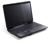
... screen brightness. Brightness up . Fully charged: The light shows blue when in AC mode. 2 Multi-in-1 Accepts Secure Digital (SD), MultiMediaCard card reader (MMC), Memory Stick (MS), Memory Stick PRO (MS PRO), xD-Picture Card (xD). English 6 Hotkey Icon + + < > + < > + < > + < > Function Description Speaker toggle Turns the speakers on and off. Volume up Increases...
... screen brightness. Brightness up . Fully charged: The light shows blue when in AC mode. 2 Multi-in-1 Accepts Secure Digital (SD), MultiMediaCard card reader (MMC), Memory Stick (MS), Memory Stick PRO (MS PRO), xD-Picture Card (xD). English 6 Hotkey Icon + + < > + < > + < > + < > Function Description Speaker toggle Turns the speakers on and off. Volume up Increases...

eMachines E627 Quick Guide - English
Page 9
Note: Do not cover or obstruct the opening of the fan. 9 Base view English # Icon Item 1 Battery bay Description Houses the computer's battery pack. 2 Battery release latch Releases the battery for removal. 3 Battery lock Locks the battery in position. 4 Hard disk bay Houses the computer's hard disk (secured with screws). 5 Memory compartment Houses the computer's main memory. 6 Ventilation slots and Enable the computer to stay cool, even cooling fan after prolonged use.
Note: Do not cover or obstruct the opening of the fan. 9 Base view English # Icon Item 1 Battery bay Description Houses the computer's battery pack. 2 Battery release latch Releases the battery for removal. 3 Battery lock Locks the battery in position. 4 Hard disk bay Houses the computer's hard disk (secured with screws). 5 Memory compartment Houses the computer's main memory. 6 Ventilation slots and Enable the computer to stay cool, even cooling fan after prolonged use.
eMachines E627 Quick Guide - English
Page 10
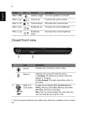
10 English Specifications Operating • system Platform • System memory • • Display • • Graphics • Storage • subsystem • • Audio • • • Communication • • • Dimensions • • ...AMD Athlon™ 64 single-core processor* • AMD M780G Chipset • IEEE 802.11b/g Dual-channel support Up to 2 GB of DDR2 667 MHz memory, upgradeable to 4 GB using two soDIMM modules 15.6" HD 1366 x 768 16:9 aspect ratio ATI Radeon™ HD 3200 Graphics 2.5" hard disk drive DVD...
10 English Specifications Operating • system Platform • System memory • • Display • • Graphics • Storage • subsystem • • Audio • • • Communication • • • Dimensions • • ...AMD Athlon™ 64 single-core processor* • AMD M780G Chipset • IEEE 802.11b/g Dual-channel support Up to 2 GB of DDR2 667 MHz memory, upgradeable to 4 GB using two soDIMM modules 15.6" HD 1366 x 768 16:9 aspect ratio ATI Radeon™ HD 3200 Graphics 2.5" hard disk drive DVD...
Service Guide
Page 5
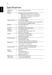
... printed Service Guide. Please note WHEN ORDERING FRU PARTS, that you with all technical information relating to -date information available on card, modem, or extra memory capability). In such cases, please contact your regional office MAY have a DIFFERENT part number code to extend the functionality of customer machines. For ACER-AUTHORIZED...
... printed Service Guide. Please note WHEN ORDERING FRU PARTS, that you with all technical information relating to -date information available on card, modem, or extra memory capability). In such cases, please contact your regional office MAY have a DIFFERENT part number code to extend the functionality of customer machines. For ACER-AUTHORIZED...
Service Guide
Page 11
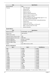
...; Vista™ Platform • AMD Athlon™ 64 X2 dual-core processor • AMD Athlon™ 64 single-core processor • AMD M780G Chipset System Memory • Low-latency, high-bandwidth • 128-bit DDR2 SDRAM controller operating at up to 333 MHz • On-board... up to 2 unbuffered SO-DIMM slots supporting DDR II 667/800. • Adjustable Maximum 128MB UMA VGA memory shared from North Bridge • Maximum memory: 2GB per slot; 4GB total • On-board cache up to 1MB Display • 15.6" WXGA, HD 720p, 1366x768 Graphics • ATI Radeon™ HD ...
...; Vista™ Platform • AMD Athlon™ 64 X2 dual-core processor • AMD Athlon™ 64 single-core processor • AMD M780G Chipset System Memory • Low-latency, high-bandwidth • 128-bit DDR2 SDRAM controller operating at up to 333 MHz • On-board... up to 2 unbuffered SO-DIMM slots supporting DDR II 667/800. • Adjustable Maximum 128MB UMA VGA memory shared from North Bridge • Maximum memory: 2GB per slot; 4GB total • On-board cache up to 1MB Display • 15.6" WXGA, HD 720p, 1366x768 Graphics • ATI Radeon™ HD ...

Service Guide
Page 16
... computer cover is active. Fully charged: The light shows green when in AC mode. 2 Multi-in-1 card Accepts Secure Digital (SD), MultiMediaCard reader (MMC), Memory Stick (MS), Memory Stick PRO (MS PRO), xD-Picture Card (xD). No. 7 8 9 Icon Item Click buttons (left and right) Palmrest HDD Description The left and right buttons...
... computer cover is active. Fully charged: The light shows green when in AC mode. 2 Multi-in-1 card Accepts Secure Digital (SD), MultiMediaCard reader (MMC), Memory Stick (MS), Memory Stick PRO (MS PRO), xD-Picture Card (xD). No. 7 8 9 Icon Item Click buttons (left and right) Palmrest HDD Description The left and right buttons...
Service Guide
Page 19
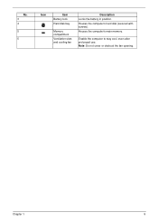
No. 3 4 5 5 Icon Item Battery lock Hard disk bay Memory compartment Ventilation slots and cooling fan Description Locks the battery in position. Note: Do not cover or obstruct the fan opening. Enable the computer to stay cool, even after prolonged use. Chapter 1 9 Houses the computer's main memory. Houses the computer's hard disk (secured with screws).
No. 3 4 5 5 Icon Item Battery lock Hard disk bay Memory compartment Ventilation slots and cooling fan Description Locks the battery in position. Note: Do not cover or obstruct the fan opening. Enable the computer to stay cool, even after prolonged use. Chapter 1 9 Houses the computer's main memory. Houses the computer's hard disk (secured with screws).
Service Guide
Page 28
...Specification ATI RS780MN + ATI SB710 4GB maximum 2 2GB 4GB (total) 200-pin +1.8V DDRII 667/800 MHz 1.8V Upto 1MB L2 Cache on CPU Memory Combinations Slot 1 0MB 0MB 0MB 512MB 512MB 512MB 1024MB 1024MB 1024MB 1024MB 2048MB 2048MB 2048MB 2048MB 512MB 1024MB 2048MB 512MB 1024MB 2048MB 0MB 512MB 1024MB... 2048MB 0MB 512MB 1024MB 2048MB Slot 2 Total Memory 512MB 1024MB 2048MB 1024MB 1536MB 2560MB 1024MB 1536MB 2048MB 3072MB 2048MB 2560MB 3072MB 4096MB NOTE: Above table lists some system...
...Specification ATI RS780MN + ATI SB710 4GB maximum 2 2GB 4GB (total) 200-pin +1.8V DDRII 667/800 MHz 1.8V Upto 1MB L2 Cache on CPU Memory Combinations Slot 1 0MB 0MB 0MB 512MB 512MB 512MB 1024MB 1024MB 1024MB 1024MB 2048MB 2048MB 2048MB 2048MB 512MB 1024MB 2048MB 512MB 1024MB 2048MB 0MB 512MB 1024MB... 2048MB 0MB 512MB 1024MB 2048MB Slot 2 Total Memory 512MB 1024MB 2048MB 1024MB 1536MB 2560MB 1024MB 1536MB 2048MB 3072MB 2048MB 2560MB 3072MB 4096MB NOTE: Above table lists some system...
Service Guide
Page 30
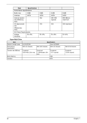
... 150 5V ±5% 8 MB SATA 395~952 (typical) 300 5V ±5% Super-Multi Drive Item Vendor & model name Performance Specification Transfer rate (MB/sec) Buffer Memory Interface HLDS GT20N With CD Diskette Specification Sony AD7580S With DVD Diskette With CD Diskette Sustained: Sustained: 3,600 KB/s (24x) max. 11.08 Mbytes/s (8x...
... 150 5V ±5% 8 MB SATA 395~952 (typical) 300 5V ±5% Super-Multi Drive Item Vendor & model name Performance Specification Transfer rate (MB/sec) Buffer Memory Interface HLDS GT20N With CD Diskette Specification Sony AD7580S With DVD Diskette With CD Diskette Sustained: Sustained: 3,600 KB/s (24x) max. 11.08 Mbytes/s (8x...
Service Guide
Page 37
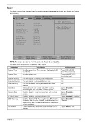
Main The Main screen allows the user to boot the system. Sets the system date. This field reports the memory size of the system. This field shows the memory allocated for your reference only. Allows startup to skip certain tests while booting, decreasing the time needed to set...or Disabled Option: Enabled or Enabled Option: Enabled or Disabled Option: AHCI or IDE Chapter 2 27 Parameter System Time System Date System Memory Extended Memory Video Memory Quiet Boot Network Boot F12 Boot Menu D2D Recovery SATA Mode Description Sets the system time. Quiet Boot: Network Boot: F12 Boot ...
Main The Main screen allows the user to boot the system. Sets the system date. This field reports the memory size of the system. This field shows the memory allocated for your reference only. Allows startup to skip certain tests while booting, decreasing the time needed to set...or Disabled Option: Enabled or Enabled Option: Enabled or Disabled Option: AHCI or IDE Chapter 2 27 Parameter System Time System Date System Memory Extended Memory Video Memory Quiet Boot Network Boot F12 Boot Menu D2D Recovery SATA Mode Description Sets the system time. Quiet Boot: Network Boot: F12 Boot ...
Service Guide
Page 43
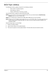
... to run the Phlash utility. Prepare a bootable diskette. 2. Copy the flash utilities to update the system BIOS flash ROM. Chapter 2 33 NOTE: Do not install memory-related drivers (XMS, EMS, DPMI) when you may not boot the system because the BIOS is required for the following conditions: • New versions of...
... to run the Phlash utility. Prepare a bootable diskette. 2. Copy the flash utilities to update the system BIOS flash ROM. Chapter 2 33 NOTE: Do not install memory-related drivers (XMS, EMS, DPMI) when you may not boot the system because the BIOS is required for the following conditions: • New versions of...

Service Guide
Page 49
... to eeprom (max. 22 characters) • dmitools /wu xxxx ==> Write uuid to eeprom • dmitools /wa xxxx ==> Write asset tag to EEPROM ( Create UUID from Memory Input: dmitools /r Output: Manufacturer (Type1, Offset04h): Acer Product Name (Type1, Offset05h): TravelMate xxxxx Serial Number (Type1, Offset07h): 01234567890123456789 UUID String (Type1, Offset08h): xxxxxxxx-xxxx-xxxx...
... to eeprom (max. 22 characters) • dmitools /wu xxxx ==> Write uuid to eeprom • dmitools /wa xxxx ==> Write asset tag to EEPROM ( Create UUID from Memory Input: dmitools /r Output: Manufacturer (Type1, Offset04h): Acer Product Name (Type1, Offset05h): TravelMate xxxxx Serial Number (Type1, Offset07h): 01234567890123456789 UUID String (Type1, Offset08h): xxxxxxxx-xxxx-xxxx...
Service Guide
Page 56
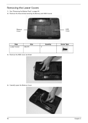
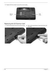
Removing the Lower Covers 1. Quantity 3 Screw Type 4. See "Removing the Battery Pack" on page 44. 2. Remove the three screws securing the Memory and HDD Covers. Carefully open the Memory Cover. 46 Chapter 3 Memory Cover HDD Cover Step Lower Covers Size M2.5*8 3. Remove the HDD cover as shown.
Removing the Lower Covers 1. Quantity 3 Screw Type 4. See "Removing the Battery Pack" on page 44. 2. Remove the three screws securing the Memory and HDD Covers. Carefully open the Memory Cover. 46 Chapter 3 Memory Cover HDD Cover Step Lower Covers Size M2.5*8 3. Remove the HDD cover as shown.
Service Guide
Page 127
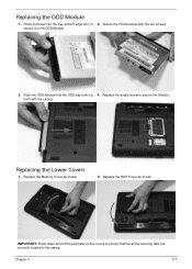
Replacing the ODD Module 1. flush with the two screws. IMPORTANT: Press down around the perimeter of the covers to secure the Module. Replace the HDD Cover as shown. 2. Push the ODD Module into the tray, bottom edge first, to the ODD Module. 3. Replace the single screw to ensure that the all the securing tabs are correctly located in the casing. Replacing the Lower Covers 1. secure it is 4. Press the bezel into the ODD bay until it to 2. Secure the ODD bracket with the casing. Replace the Memory Cover as shown. Chapter 3 117
Replacing the ODD Module 1. flush with the two screws. IMPORTANT: Press down around the perimeter of the covers to secure the Module. Replace the HDD Cover as shown. 2. Push the ODD Module into the tray, bottom edge first, to the ODD Module. 3. Replace the single screw to ensure that the all the securing tabs are correctly located in the casing. Replacing the Lower Covers 1. secure it is 4. Press the bezel into the ODD bay until it to 2. Secure the ODD bracket with the casing. Replace the Memory Cover as shown. Chapter 3 117
Service Guide
Page 128
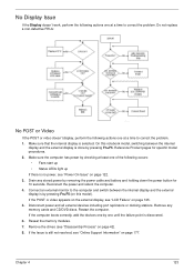
Push until the card clicks into the slot as shown. 2. Insert the SD Dummy Card into place and is flush with the casing. 118 Chapter 3 Memory Cover HDD Cover Replacing the SD Dummy Card 1. Replace the three screws to secure the covers in place. 3.
Push until the card clicks into the slot as shown. 2. Insert the SD Dummy Card into place and is flush with the casing. 118 Chapter 3 Memory Cover HDD Cover Replacing the SD Dummy Card 1. Replace the three screws to secure the covers in place. 3.
Service Guide
Page 133
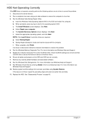
Drain any memory cards and CD/DVD discs. Remove the drives (see "LCD Failure" on page 125. 5. Reconnect the power and reboot the computer. 4. If the computer boots .... Disconnect power and all external devices including port replicators or docking stations. Remove any stored power by pressing Fn+F5 (on page 42). 8. Reseat the memory modules. 7.
Drain any memory cards and CD/DVD discs. Remove the drives (see "LCD Failure" on page 125. 5. Reconnect the power and reboot the computer. 4. If the computer boots .... Disconnect power and all external devices including port replicators or docking stations. Remove any stored power by pressing Fn+F5 (on page 42). 8. Reseat the memory modules. 7.
Service Guide
Page 134
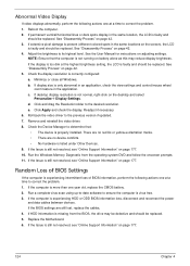
... displays abnormally, perform the following actions one year old, replace the CMOS battery. 2. See "Disassembly Process" on page 42. 4. c. Readjust if necessary. 6. Run the Windows Memory Diagnostic from the BIOS, the drive may reduce display brightness. If HDD information is more than one at a time to correct the problem. 1. Remove and...
... displays abnormally, perform the following actions one year old, replace the CMOS battery. 2. See "Disassembly Process" on page 42. 4. c. Readjust if necessary. 6. Run the Windows Memory Diagnostic from the BIOS, the drive may reduce display brightness. If HDD information is more than one at a time to correct the problem. 1. Remove and...
Service Guide
Page 138
... one at a time to ensure the computer is set correctly. 7. Run the Windows Vista Startup Repair Utility: a. The Install Windows screen displays. Run the Windows Memory Diagnostic Tool. Ensure all external devices. 2. Disconnect all cables and jumpers on the HDD and ODD are required. Run a complete virus scan using System Restore...
... one at a time to ensure the computer is set correctly. 7. Run the Windows Vista Startup Repair Utility: a. The Install Windows screen displays. Run the Windows Memory Diagnostic Tool. Ensure all external devices. 2. Disconnect all cables and jumpers on the HDD and ODD are required. Run a complete virus scan using System Restore...
Service Guide
Page 145
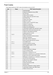
... describe the POST codes and descriptions during warm boot Initialize PCI Bus Mastering devices Initialize keyboard controller BIOS ROM checksum Initialize cache before memory autosize 8254 timer initialization 8237 DMA controller initialization Reset Programmable Interrupt Controller Test DRAM refresh Test 8742 Keyboard Controller Set ES segment register... to 4 GB Enable A20 line Autosize DRAM Initialize POST Memory Manager Clear 512 KB base RAM RAM failure on address line xxxx* RAM failure on data bits xxxx* of low byte of...
... describe the POST codes and descriptions during warm boot Initialize PCI Bus Mastering devices Initialize keyboard controller BIOS ROM checksum Initialize cache before memory autosize 8254 timer initialization 8237 DMA controller initialization Reset Programmable Interrupt Controller Test DRAM refresh Test 8742 Keyboard Controller Set ES segment register... to 4 GB Enable A20 line Autosize DRAM Initialize POST Memory Manager Clear 512 KB base RAM RAM failure on address line xxxx* RAM failure on data bits xxxx* of low byte of...
Service Guide
Page 146
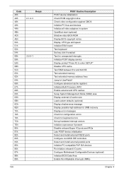
... interrupts Initialize POST display service Display prompt "Press F2 to enter SETUP" Disable CPU cache Test RAM between 512 and 640 KB Test extended memory Test extended memory address lines Jump to UserPatch1 Configure advanced cache registers Initialize Multi Processor APIC Enable external and CPU caches Setup System Management Mode (SMM) area...
... interrupts Initialize POST display service Display prompt "Press F2 to enter SETUP" Disable CPU cache Test RAM between 512 and 640 KB Test extended memory Test extended memory address lines Jump to UserPatch1 Configure advanced cache registers Initialize Multi Processor APIC Enable external and CPU caches Setup System Management Mode (SMM) area...


