User Guide
Page 3
... Connection 23 Hardware Overview ...27 The Web Configurator ...35 Initial Setup Example ...44 Tutorials ...48 Technical Reference ...53 System Status and Port Statistics 55 Basic Setting ...73 VDSL Setup ...99 VLAN ...129 Static MAC Forward Setup ...152 Static Multicast Forward Setup 154 Filtering ...158 Spanning Tree Protocol ...160 Broadcast Storm Control... ...267 CFM ...271 VLAN Mapping ...275 Layer 2 Protocol Tunneling ...279 DoS Prevention ...283 PPPoE IA ...285 SFP Threshold ...291 Static Route ...295 Differentiated Services ...298 VES1724-56 User's Guide 3
... Connection 23 Hardware Overview ...27 The Web Configurator ...35 Initial Setup Example ...44 Tutorials ...48 Technical Reference ...53 System Status and Port Statistics 55 Basic Setting ...73 VDSL Setup ...99 VLAN ...129 Static MAC Forward Setup ...152 Static Multicast Forward Setup 154 Filtering ...158 Spanning Tree Protocol ...160 Broadcast Storm Control... ...267 CFM ...271 VLAN Mapping ...275 Layer 2 Protocol Tunneling ...279 DoS Prevention ...283 PPPoE IA ...285 SFP Threshold ...291 Static Route ...295 Differentiated Services ...298 VES1724-56 User's Guide 3
User Guide
Page 6
... Initial Setup Example...44 5.1 Overview ...44 5.2 Configuring Switch Management IP Address 44 5.2.1 Creating a VLAN ...45 5.2.2 Setting Port VID ...46 Chapter 6 Tutorials ...48 6.1 How to Use DHCP Relay Per VLAN on the Switch 48 6.1.1 ...Settings 51 6.1.5 Testing the Connection 52 Part II: Technical Reference 53 Chapter 7 System Status and Port Statistics 55 7.1 Overview ...55 7.2 Port Status Summary ...55 7.2.1 VDSL Port Status Change 56 7.2.2 VDSL Port Details ...57 7.2.3 VDSL Summary ...67 7.2.4 VTUR Counter ...68 7.2.5 Port Details ...70 Chapter 8 Basic Setting ...73 6 VES1724-56...
... Initial Setup Example...44 5.1 Overview ...44 5.2 Configuring Switch Management IP Address 44 5.2.1 Creating a VLAN ...45 5.2.2 Setting Port VID ...46 Chapter 6 Tutorials ...48 6.1 How to Use DHCP Relay Per VLAN on the Switch 48 6.1.1 ...Settings 51 6.1.5 Testing the Connection 52 Part II: Technical Reference 53 Chapter 7 System Status and Port Statistics 55 7.1 Overview ...55 7.2 Port Status Summary ...55 7.2.1 VDSL Port Status Change 56 7.2.2 VDSL Port Details ...57 7.2.3 VDSL Summary ...67 7.2.4 VTUR Counter ...68 7.2.5 Port Details ...70 Chapter 8 Basic Setting ...73 6 VES1724-56...
User Guide
Page 8
... VLAN ...132 10.5.1 Static VLAN Status 132 10.5.2 VLAN Details ...133 10.5.3 Configure a Static VLAN 134 10.5.4 Configure a VLAN Profile 135 10.5.5 Configure VLAN Port Settings 137 10.6 Subnet Based VLANs ...138 10.7 Configuring Subnet Based VLAN 139 10.8 Protocol Based VLANs ...141 10.9 Configuring Protocol Based VLAN 142 10.10... Multicast Forwarding Overview 154 12.2 Configuring Static Multicast Forwarding 155 Chapter 13 Filtering...158 13.1 Configure a Filtering Rule 158 Chapter 14 Spanning Tree Protocol...160 8 VES1724-56 User's Guide
... VLAN ...132 10.5.1 Static VLAN Status 132 10.5.2 VLAN Details ...133 10.5.3 Configure a Static VLAN 134 10.5.4 Configure a VLAN Profile 135 10.5.5 Configure VLAN Port Settings 137 10.6 Subnet Based VLANs ...138 10.7 Configuring Subnet Based VLAN 139 10.8 Protocol Based VLANs ...141 10.9 Configuring Protocol Based VLAN 142 10.10... Multicast Forwarding Overview 154 12.2 Configuring Static Multicast Forwarding 155 Chapter 13 Filtering...158 13.1 Configure a Filtering Rule 158 Chapter 14 Spanning Tree Protocol...160 8 VES1724-56 User's Guide
User Guide
Page 9
... Aggregation ...180 17.1 Link Aggregation Overview 180 17.2 Dynamic Link Aggregation 180 17.2.1 Link Aggregation ID 181 17.3 Link Aggregation Status 181 17.4 Link Aggregation Setting 182 17.5 Link Aggregation Control Protocol 183 17.6 Static Trunking Example 184 Chapter 18 Port Authentication ...186 18.1 Port Authentication Overview 186 18.1.1 IEEE 802....1.2 MAC Authentication 187 18.2 Port Authentication Configuration 188 18.2.1 Activate IEEE 802.1x Security 188 18.2.2 Activate MAC Authentication 189 Chapter 19 MAC Limit ...191 VES1724-56 User's Guide 9
... Aggregation ...180 17.1 Link Aggregation Overview 180 17.2 Dynamic Link Aggregation 180 17.2.1 Link Aggregation ID 181 17.3 Link Aggregation Status 181 17.4 Link Aggregation Setting 182 17.5 Link Aggregation Control Protocol 183 17.6 Static Trunking Example 184 Chapter 18 Port Authentication ...186 18.1 Port Authentication Overview 186 18.1.1 IEEE 802....1.2 MAC Authentication 187 18.2 Port Authentication Configuration 188 18.2.1 Activate IEEE 802.1x Security 188 18.2.2 Activate MAC Authentication 189 Chapter 19 MAC Limit ...191 VES1724-56 User's Guide 9
User Guide
Page 11
... 24.1.4 IGMP Snooping and VLANs 218 24.1.5 IGMP Proxy ...218 24.1.6 Multicast Listener Discovery 218 24.1.7 MLD Messages ...218 24.2 Multicast Status ...219 24.3 Multicast Setting ...221 24.4 IGMP Snooping VLAN ...223 24.5 IGMP Filtering Profile ...224 24.6 MVR Overview ...225 24.6.1 Types of MVR Ports 226 24.6.2 MVR Modes ...226... Source Guard ...250 26.3 IP Source Guard Static Binding 250 26.4 DHCP Snooping ...252 26.5 DHCP Snooping Configure 254 26.5.1 DHCP Snooping Port Configure 256 VES1724-56 User's Guide 11
... 24.1.4 IGMP Snooping and VLANs 218 24.1.5 IGMP Proxy ...218 24.1.6 Multicast Listener Discovery 218 24.1.7 MLD Messages ...218 24.2 Multicast Status ...219 24.3 Multicast Setting ...221 24.4 IGMP Snooping VLAN ...223 24.5 IGMP Filtering Profile ...224 24.6 MVR Overview ...225 24.6.1 Types of MVR Ports 226 24.6.2 MVR Modes ...226... Source Guard ...250 26.3 IP Source Guard Static Binding 250 26.4 DHCP Snooping ...252 26.5 DHCP Snooping Configure 254 26.5.1 DHCP Snooping Port Configure 256 VES1724-56 User's Guide 11
User Guide
Page 13
...-blind Mode 300 35.2.2 TRTCM-Color-aware Mode 300 35.3 Activating DiffServ ...300 35.3.1 Configuring 2-Rate 3 Color Marker Settings 301 35.4 DSCP-to-IEEE 802.1p Priority Settings 303 35.4.1 Configuring DSCP Settings 303 Chapter 36 DHCP...305 36.1 DHCP Overview ...305 36.1.1 DHCP Modes ...305 36.1.2 DHCP Configuration Options 305 36... Format 306 36.3.3 Sub-Option Format 307 36.3.4 Configuring DHCP Global Relay 307 36.3.5 Global DHCP Relay Configuration Example 309 36.4 Configuring DHCP VLAN Settings 310 36.4.1 Example: DHCP Relay for Two VLANs 311 VES1724-56 User's Guide 13
...-blind Mode 300 35.2.2 TRTCM-Color-aware Mode 300 35.3 Activating DiffServ ...300 35.3.1 Configuring 2-Rate 3 Color Marker Settings 301 35.4 DSCP-to-IEEE 802.1p Priority Settings 303 35.4.1 Configuring DSCP Settings 303 Chapter 36 DHCP...305 36.1 DHCP Overview ...305 36.1.1 DHCP Modes ...305 36.1.2 DHCP Configuration Options 305 36... Format 306 36.3.3 Sub-Option Format 307 36.3.4 Configuring DHCP Global Relay 307 36.3.5 Global DHCP Relay Configuration Example 309 36.4 Configuring DHCP VLAN Settings 310 36.4.1 Example: DHCP Relay for Two VLANs 311 VES1724-56 User's Guide 13
User Guide
Page 14
... 38.3.1 SNMP v3 and Security 321 38.3.2 Supported MIBs ...322 38.3.3 SNMP Traps ...322 38.3.4 Configuring SNMP 326 38.3.5 Configuring SNMP Trap Group 328 38.3.6 Setting Up Login Accounts 328 38.4 SSH Overview ...330 38.5 How SSH works ...330 38.6 SSH Implementation on the Switch 331 38.6.1 Requirements for Using SSH... 336 38.8.4 The Main Screen ...337 38.9 Service Port Access Control 338 38.10 Remote Management 339 Chapter 39 Diagnostic ...341 39.1 Diagnostic ...341 14 VES1724-56 User's Guide
... 38.3.1 SNMP v3 and Security 321 38.3.2 Supported MIBs ...322 38.3.3 SNMP Traps ...322 38.3.4 Configuring SNMP 326 38.3.5 Configuring SNMP Trap Group 328 38.3.6 Setting Up Login Accounts 328 38.4 SSH Overview ...330 38.5 How SSH works ...330 38.6 SSH Implementation on the Switch 331 38.6.1 Requirements for Using SSH... 336 38.8.4 The Main Screen ...337 38.9 Service Port Access Control 338 38.10 Remote Management 339 Chapter 39 Diagnostic ...341 39.1 Diagnostic ...341 14 VES1724-56 User's Guide
User Guide
Page 21
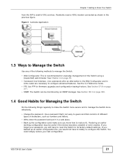
...the Switch. • Web Configurator. You could simply restore your password, you would not have to reset the Switch to its factory default settings. Figure 2 Curbside Application 1.3 Ways to Manage the Switch Use any of characters, such as shown in the previous figure. If you ...browser. See Chapter 4 on page 317. • SNMP. Use FTP for Managing the Switch Do the following methods to configure advanced features. VES1724-56 User's Guide 21 The Switch can be useful if the device becomes unstable or even crashes. If you forget your last configuration. This is recommended...
...the Switch. • Web Configurator. You could simply restore your password, you would not have to reset the Switch to its factory default settings. Figure 2 Curbside Application 1.3 Ways to Manage the Switch Use any of characters, such as shown in the previous figure. If you ...browser. See Chapter 4 on page 317. • SNMP. Use FTP for Managing the Switch Do the following methods to configure advanced features. VES1724-56 User's Guide 21 The Switch can be useful if the device becomes unstable or even crashes. If you forget your last configuration. This is recommended...
User Guide
Page 23
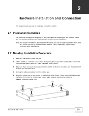
...attachment of the Switch and the connected cables. Make sure there is a power outlet nearby. 3 Make sure there is clean and dry. 2 Set the Switch on a standard EIA rack. This is especially important for enclosed rack installations. 2.2 Desktop Installation Procedure 1 Make sure the Switch is ... the power cord. 4 Remove the adhesive backing from shock or vibration and ensure space between devices when stacking. Figure 3 Attaching Rubber Feet VES1724-56 User's Guide 23 These rubber feet help protect the Switch from the rubber feet. 5 Attach the rubber feet to install and connect the ...
...attachment of the Switch and the connected cables. Make sure there is a power outlet nearby. 3 Make sure there is clean and dry. 2 Set the Switch on a standard EIA rack. This is especially important for enclosed rack installations. 2.2 Desktop Installation Procedure 1 Make sure the Switch is ... the power cord. 4 Remove the adhesive backing from shock or vibration and ensure space between devices when stacking. Figure 3 Attaching Rubber Feet VES1724-56 User's Guide 23 These rubber feet help protect the Switch from the rubber feet. 5 Attach the rubber feet to install and connect the ...
User Guide
Page 28
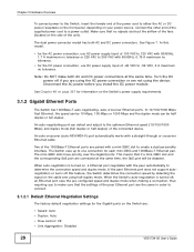
... (full duplex or half duplex) of the connected device. The Switch uses up to connect. 3.1.2.1 Default Ethernet Negotiation Settings The factory default negotiation settings for each mini-GBIC and 1000Base-T Ethernet pair. If the peer Ethernet port does not support autonegotiation or turns off ...• Speed: Auto • Duplex: Auto • Flow control: Off • Link Aggregation: Disabled 28 VES1724-56 User's Guide Connect the other end of the supplied power cord to -56 VDC, 4 A maximum no tolerance. • for information on page 367 for the DC power connection, use ...
... (full duplex or half duplex) of the connected device. The Switch uses up to connect. 3.1.2.1 Default Ethernet Negotiation Settings The factory default negotiation settings for each mini-GBIC and 1000Base-T Ethernet pair. If the peer Ethernet port does not support autonegotiation or turns off ...• Speed: Auto • Duplex: Auto • Flow control: Off • Link Aggregation: Disabled 28 VES1724-56 User's Guide Connect the other end of the supplied power cord to -56 VDC, 4 A maximum no tolerance. • for information on page 367 for the DC power connection, use ...

User Guide
Page 38
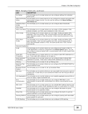
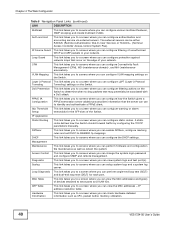
... identification information about the Switch. IP Setup This link takes you to 64 IPv4 routing domains. 38 VES1724-56 User's Guide Table 5 Navigation Panel Links LINK DESCRIPTION Basic Settings System Info This link takes you can set up global Switch parameters such as VLAN type, MAC address learning, GARP and priority queues. General Setup...
... identification information about the Switch. IP Setup This link takes you to 64 IPv4 routing domains. 38 VES1724-56 User's Guide Table 5 Navigation Panel Links LINK DESCRIPTION Basic Settings System Info This link takes you can set up global Switch parameters such as VLAN type, MAC address learning, GARP and priority queues. General Setup...
User Guide
Page 39
...to perform special treatment on the specified criteria. Classifier This link takes you to a screen where you can configure alarm thresholds. VES1724-56 User's Guide 39 Hardware Alarm This link takes you to screens where you can configure queuing with associated queue weights for clients...VDSL alarm template for individual Switch ports. MAC Limit This link takes you to a screen where you can activate MAC address learning and set up broadcast filters. Chapter 4 The Web Configurator Table 5 Navigation Panel Links (continued) LINK DESCRIPTION Port Setup This link takes you ...
...to perform special treatment on the specified criteria. Classifier This link takes you to a screen where you can configure alarm thresholds. VES1724-56 User's Guide 39 Hardware Alarm This link takes you to screens where you can configure queuing with associated queue weights for clients...VDSL alarm template for individual Switch ports. MAC Limit This link takes you to a screen where you can activate MAC address learning and set up broadcast filters. Chapter 4 The Web Configurator Table 5 Navigation Panel Links (continued) LINK DESCRIPTION Port Setup This link takes you ...
User Guide
Page 40
... static routes. Auth and Acct This link takes you to a screen where you can configure L2PT (Layer 2 Protocol Tunneling Tunneling) settings on the Switch to determine when to a screen where you can configure authentication and accounting service via external servers. DoS Prevention This ... file maintenance as well as CPU, packet buffer, memory utilization. 40 VES1724-56 User's Guide DiffServ This link takes you to screens where you can enable DiffServ, configure marking rules and set DSCP-to screens where you can configure filtering of your network. Hardware ...
... static routes. Auth and Acct This link takes you to a screen where you can configure L2PT (Layer 2 Protocol Tunneling Tunneling) settings on the Switch to determine when to a screen where you can configure authentication and accounting service via external servers. DoS Prevention This ... file maintenance as well as CPU, packet buffer, memory utilization. 40 VES1724-56 User's Guide DiffServ This link takes you to screens where you can enable DiffServ, configure marking rules and set DSCP-to screens where you can configure filtering of your network. Hardware ...
User Guide
Page 41
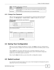
... your configuration to nonvolatile memory. Click the Save link in the run -time memory. Settings in the upper right hand corner of the following: VES1724-56 User's Guide 41 Note: Use the Save link when you are done modifying the settings in for the first time, it is turned off . Figure 16 Change Administrator...
... your configuration to nonvolatile memory. Click the Save link in the run -time memory. Settings in the upper right hand corner of the following: VES1724-56 User's Guide 41 Note: Use the Save link when you are done modifying the settings in for the first time, it is turned off . Figure 16 Change Administrator...
User Guide
Page 42
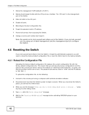
... bps with 8 data bits, no parity, one stop bit and flow control set to enter debug mode. 4 Type atlc after the "Enter Debug Mode" message. 5 Wait for the "Starting XMODEM upload" message before activating XMODEM upload on your terminal. 42 VES1724-56 User's Guide The "CPU port" is VLAN 1). 2 Delete all traffic to...
... bps with 8 data bits, no parity, one stop bit and flow control set to enter debug mode. 4 Type atlc after the "Enter Debug Mode" message. 5 Wait for the "Starting XMODEM upload" message before activating XMODEM upload on your terminal. 42 VES1724-56 User's Guide The "CPU port" is VLAN 1). 2 Delete all traffic to...
User Guide
Page 44
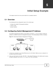
... Configurator. The following lists the configuration steps for the initial setup: • Configure the Switch IP management address • Create a VLAN • Set port VLAN ID 5.2 Configuring Switch Management IP Address The default management IP address of the Switch is in the same subnet as the Switch. 2 Open... IP address) in the address bar to an in a different subnet for more information. CHAPTER 5 Initial Setup Example This chapter shows how to set up the Switch for an example network. 5.1 Overview The following figure shows an example. VES1724-56 User's Guide 44
... Configurator. The following lists the configuration steps for the initial setup: • Configure the Switch IP management address • Create a VLAN • Set port VLAN ID 5.2 Configuring Switch Management IP Address The default management IP address of the Switch is in the same subnet as the Switch. 2 Open... IP address) in the address bar to an in a different subnet for more information. CHAPTER 5 Initial Setup Example This chapter shows how to set up the Switch for an example network. 5.1 Overview The following figure shows an example. VES1724-56 User's Guide 44
User Guide
Page 45
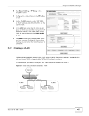
... tagged static VLAN with fixed port members. This is turned off. 5.2.1 Creating a VLAN Chapter 5 Initial Setup Example VLANs confine broadcast frames to belong. Settings in the run-time memory are lost when the Switch's power is the same as the VLAN ID you want to configure port 1 and port... 6 In the VID field, enter the ID of VLAN 2. Figure 20 Initial Setup Network Example: VLAN Internet port1 VLAN1 192.168.1.x 192.168.1.x VLAN2 VES1724-56 User's Guide 45 You can do this management IP address to the VLAN group in which you configure in the IP Setup screen. 5 For the...
... tagged static VLAN with fixed port members. This is turned off. 5.2.1 Creating a VLAN Chapter 5 Initial Setup Example VLANs confine broadcast frames to belong. Settings in the run-time memory are lost when the Switch's power is the same as the VLAN ID you want to configure port 1 and port... 6 In the VID field, enter the ID of VLAN 2. Figure 20 Initial Setup Network Example: VLAN Internet port1 VLAN1 192.168.1.x 192.168.1.x VLAN2 VES1724-56 User's Guide 45 You can do this management IP address to the VLAN group in which you configure in the IP Setup screen. 5 For the...
User Guide
Page 46
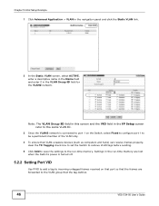
...Setup screen refer to the same VLAN ID. 3 Since the VLAN2 network is turned off. 5.2.2 Setting Port VID Use PVID to add a tag to incoming untagged frames received on the Switch, select ...Fixed to configure port 1 to the run-time memory. Settings in the VLAN Group ID field for the VLAN2 network. Chapter 5 Initial Setup Example 1 Click Advanced... box to set the Switch to remove VLAN tags before sending. 5 Click Add to save the settings to be a permanent member of the VLAN only. 4 To ensure that the tag defines. 46 VES1724-56 User's Guide...
...Setup screen refer to the same VLAN ID. 3 Since the VLAN2 network is turned off. 5.2.2 Setting Port VID Use PVID to add a tag to incoming untagged frames received on the Switch, select ...Fixed to configure port 1 to the run-time memory. Settings in the VLAN Group ID field for the VLAN2 network. Chapter 5 Initial Setup Example 1 Click Advanced... box to set the Switch to remove VLAN tags before sending. 5 Click Add to save the settings to be a permanent member of the VLAN only. 4 To ensure that the tag defines. 46 VES1724-56 User's Guide...
User Guide
Page 47
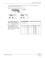
Then click the VLAN Port Setting link. 2 Enter 2 in the PVID field for port 1 and click Apply to save your changes back to VLAN 2. Settings in the navigation panel. Figure 21 Initial Setup Network Example: Port VID 1 Click Advanced Applications > VLAN in the run -time memory. VES1724-56 User's Guide 47 Chapter 5 Initial Setup Example In the example network, configure 2 as the port VID on port 1 so that any untagged frames received on that port get sent to the run -time memory are lost when the Switch's power is turned off.
Then click the VLAN Port Setting link. 2 Enter 2 in the PVID field for port 1 and click Apply to save your changes back to VLAN 2. Settings in the navigation panel. Figure 21 Initial Setup Network Example: Port VID 1 Click Advanced Applications > VLAN in the run -time memory. VES1724-56 User's Guide 47 Chapter 5 Initial Setup Example In the example network, configure 2 as the port VID on port 1 so that any untagged frames received on that port get sent to the run -time memory are lost when the Switch's power is turned off.
User Guide
Page 48
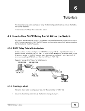
... CPE A 192.168.2.3 6.1.2 Creating a VLAN Follow the steps below to configure ports 2 and 18 as a member of using the Web Configurator to set up and use the Switch. VES1724-56 User's Guide 48 The DHCP server can then assign a specific IP address based on the system name, VLAN ID and port number in...
... CPE A 192.168.2.3 6.1.2 Creating a VLAN Follow the steps below to configure ports 2 and 18 as a member of using the Web Configurator to set up and use the Switch. VES1724-56 User's Guide 48 The DHCP server can then assign a specific IP address based on the system name, VLAN ID and port number in...


