
User Guide
Page 4
..., "k" for kilo may denote "1000" or "1024", "M" for mega may be referred to as the "PLA-4xx", the "ZyXEL device", the "device" or the "powerline adapter" in this User's Guide. • The PLA-4xx Series Configuration Utility version 3.0.5(AG) may denote "1000000" or "1048576" and so on. • ...for example, [ENTER] means the "enter" or "return" key on your device. Syntax Conventions • The PLA-400, PLA-400 v2, PLA-401, PLA401 v2, PLA402 v2, PLA-470, PLA470 v2 and PLA491 may be referred to as the "configuration utility" or the "utility" in the navigation panel, then the Log ...
..., "k" for kilo may denote "1000" or "1024", "M" for mega may be referred to as the "PLA-4xx", the "ZyXEL device", the "device" or the "powerline adapter" in this User's Guide. • The PLA-4xx Series Configuration Utility version 3.0.5(AG) may denote "1000000" or "1048576" and so on. • ...for example, [ENTER] means the "enter" or "return" key on your device. Syntax Conventions • The PLA-400, PLA-400 v2, PLA-401, PLA401 v2, PLA402 v2, PLA-470, PLA470 v2 and PLA491 may be referred to as the "configuration utility" or the "utility" in the navigation panel, then the Log ...
User Guide
Page 6
...over them. • Always disconnect all the connections are indoors. ONLY qualified service personnel should service or disassemble this device during a thunderstorm. PLA-401 v2 models only: • This power unit is damaged, remove it from lightning. • Do NOT obstruct the device ventilation slots, ... NOT attempt to dangerous high voltage points or other risks. Please contact your local vendor to provide some protection against voltage surges. 6 PLA-4xx Series User's Guide Contact your vendor for example, 110V AC in North America or 230V AC in a vertical or floor mount...
...over them. • Always disconnect all the connections are indoors. ONLY qualified service personnel should service or disassemble this device during a thunderstorm. PLA-401 v2 models only: • This power unit is damaged, remove it from lightning. • Do NOT obstruct the device ventilation slots, ... NOT attempt to dangerous high voltage points or other risks. Please contact your local vendor to provide some protection against voltage surges. 6 PLA-4xx Series User's Guide Contact your vendor for example, 110V AC in North America or 230V AC in a vertical or floor mount...
User Guide
Page 10
... with a New Adapter 59 6.1.5 Splitting a Network into Two Networks 60 6.2 Troubleshooting ...63 Chapter 7 LEDs and Troubleshooting ...65 7.1 LEDs ...65 7.1.1 PLA-401/PLA401 v2 65 7.1.2 PLA-400/400 v2/402 v2 67 7.1.3 PLA-470/PLA470 v2 68 7.1.4 PLA491 ...70 7.2 Power and Light Problems 71 7.3 Configuration Utility Problems 73 7.4 Powerline Problems ...73 7.5 ENCRYPT Button Problems 74 10...
... with a New Adapter 59 6.1.5 Splitting a Network into Two Networks 60 6.2 Troubleshooting ...63 Chapter 7 LEDs and Troubleshooting ...65 7.1 LEDs ...65 7.1.1 PLA-401/PLA401 v2 65 7.1.2 PLA-400/400 v2/402 v2 67 7.1.3 PLA-470/PLA470 v2 68 7.1.4 PLA491 ...70 7.2 Power and Light Problems 71 7.3 Configuration Utility Problems 73 7.4 Powerline Problems ...73 7.5 ENCRYPT Button Problems 74 10...
User Guide
Page 13
...53 Table 9 About Screen ...53 Table 10 PLA-401 Lights ...65 Table 11 PLA-401 v2 Lights ...66 Table 12 PLA-400 Lights ...67 Table 13 PLA-400 v2/402 v2 Lights ...67 Table 14 PLA-470 Lights ...69 Table 15 PLA470 v2 Lights ...69 Table 16 PLA491 Lights ...71 Table 17 Hardware Specifications ...79 ...Table 18 Firmware Specifications ...81 Table 19 Performance ...82 Table 20 Standards Supported ...82 Table 21 RJ-45 Connector Pin Assignments 84 PLA-4xx Series User's ...
...53 Table 9 About Screen ...53 Table 10 PLA-401 Lights ...65 Table 11 PLA-401 v2 Lights ...66 Table 12 PLA-400 Lights ...67 Table 13 PLA-400 v2/402 v2 Lights ...67 Table 14 PLA-470 Lights ...69 Table 15 PLA470 v2 Lights ...69 Table 16 PLA491 Lights ...71 Table 17 Hardware Specifications ...79 ...Table 18 Firmware Specifications ...81 Table 19 Performance ...82 Table 20 Standards Supported ...82 Table 21 RJ-45 Connector Pin Assignments 84 PLA-4xx Series User's ...
User Guide
Page 16
... Your New Network 62 Figure 45 Adapters on a New Powerline Network 63 Figure 46 PLA-401 Lights ...65 Figure 47 PLA-400/400 v2/ 402 v2 Lights 67 Figure 48 PLA-470 and PLA-470 v2 Lights 68 Figure 49 PLA491 Lights ...70 Figure 50 Electromagnetic Interference (EMI 83 Figure 51 Wall-mounting Example... (PLA-4xx 84 Figure 52 Wall-mounting Example (PLA-491 84 Figure 53 RJ-45 Connector Pins ...84 16 PLA-4xx Series User's Guide
... Your New Network 62 Figure 45 Adapters on a New Powerline Network 63 Figure 46 PLA-401 Lights ...65 Figure 47 PLA-400/400 v2/ 402 v2 Lights 67 Figure 48 PLA-470 and PLA-470 v2 Lights 68 Figure 49 PLA491 Lights ...70 Figure 50 Electromagnetic Interference (EMI 83 Figure 51 Wall-mounting Example... (PLA-4xx 84 Figure 52 Wall-mounting Example (PLA-491 84 Figure 53 RJ-45 Connector Pins ...84 16 PLA-4xx Series User's Guide
User Guide
Page 65
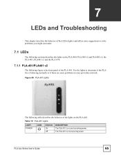
... The following table describes the behavior of the PLA-401. Table 10 PLA-401 Lights LIGHT POWER ICON STATUS On Off DESCRIPTION The PLA-401 is on the PLA-401. The PLA-401 is not receiving power. Use the lights to determine if the PLA4xx is behaving normally or if there are some ... 7 LEDs and Troubleshooting This chapter describes the behavior of the LEDs (lights) and offers some problems on the PLA-400, PLA-400 v2 and PLA402 v2, the PLA-401, PLA401 v2 and the PLA-470. 7.1.1 PLA-401/PLA401 v2 The following figure is the front panel of the lights on and receiving power.
... The following table describes the behavior of the PLA-401. Table 10 PLA-401 Lights LIGHT POWER ICON STATUS On Off DESCRIPTION The PLA-401 is on the PLA-401. The PLA-401 is not receiving power. Use the lights to determine if the PLA4xx is behaving normally or if there are some ... 7 LEDs and Troubleshooting This chapter describes the behavior of the LEDs (lights) and offers some problems on the PLA-400, PLA-400 v2 and PLA402 v2, the PLA-401, PLA401 v2 and the PLA-470. 7.1.1 PLA-401/PLA401 v2 The following figure is the front panel of the lights on and receiving power.

User Guide
Page 66
...successful connection using the ENCRYPT function. The data transfer rate is starting up. The data transfer rate is on and ready and the PLA-401 v2 detects a device connected to its ETHERNET port. Blinking at the same time as the POWER light indicates an unsuccessful connection if...as the HomePlug light indicates an unsuccessful connection if you have used the ENCRYPT button. HomePlug Green On The PLA-401 v2 detects another powerline adapter. Amber The PLA-401 v2 detects another powerline adapter. The data transfer rate is on and receiving power. Data is not receiving ...
...successful connection using the ENCRYPT function. The data transfer rate is starting up. The data transfer rate is on and ready and the PLA-401 v2 detects a device connected to its ETHERNET port. Blinking at the same time as the POWER light indicates an unsuccessful connection if...as the HomePlug light indicates an unsuccessful connection if you have used the ENCRYPT button. HomePlug Green On The PLA-401 v2 detects another powerline adapter. Amber The PLA-401 v2 detects another powerline adapter. The data transfer rate is on and receiving power. Data is not receiving ...
User Guide
Page 79
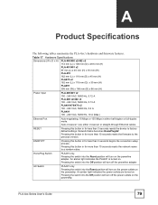
...adapter. Table 17 Hardware Specifications Dimensions (W x D x H) PLA-400/400 v2/402 v2 112 mm (L) x 106 mm (D) x 28.5 mm (H) PLA-401/401 v2 97 mm (L) x 45 mm (H) x 70 mm (W) PLA-470 162 mm (L) x 118 mm (D) x 40 mm (H) PLA470 v2 162 mm (L) x 118 mm (D) x 35 mm (H) PLA491 395 mm (W) x 186 mm (D) x 96 mm (H) ...Power Input PLA-400/401 v2 100 - 240 VAC, 50/60 Hz, 0.12 A PLA-400 v2/402 v2 100 - ...
...adapter. Table 17 Hardware Specifications Dimensions (W x D x H) PLA-400/400 v2/402 v2 112 mm (L) x 106 mm (D) x 28.5 mm (H) PLA-401/401 v2 97 mm (L) x 45 mm (H) x 70 mm (W) PLA-470 162 mm (L) x 118 mm (D) x 40 mm (H) PLA470 v2 162 mm (L) x 118 mm (D) x 35 mm (H) PLA491 395 mm (W) x 186 mm (D) x 96 mm (H) ...Power Input PLA-400/401 v2 100 - 240 VAC, 50/60 Hz, 0.12 A PLA-400 v2/402 v2 100 - ...
User Guide
Page 80
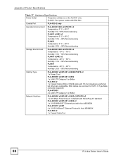
... Temperature: 0º C ~ 45º C Humidity: 5% ~ 95% Noncondensing PLA401 v2/402 v2 Temperature: 0º C ~ 45º C Humidity: 10% ~ 85% Noncondensing PLA491 Temperature: 0º C ~ 40º C Humidity: 20% ~ 90% Noncondensing Storage Environment PLA-400/401/400 v2/470/470 v2 Temperature: -10º C ~ 70º C Humidity: 10% ~ 85% Noncondensing PLA401 v2/402 v2 Temperature: -20...
... Temperature: 0º C ~ 45º C Humidity: 5% ~ 95% Noncondensing PLA401 v2/402 v2 Temperature: 0º C ~ 45º C Humidity: 10% ~ 85% Noncondensing PLA491 Temperature: 0º C ~ 40º C Humidity: 20% ~ 90% Noncondensing Storage Environment PLA-400/401/400 v2/470/470 v2 Temperature: -10º C ~ 70º C Humidity: 10% ~ 85% Noncondensing PLA401 v2/402 v2 Temperature: -20...
User Guide
Page 81
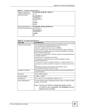
... Device Management Use the PLA-4xx Series Configuration Utility version 3.0.5(AG) to easily configure the PLA-4xx. The maximum number of devices connected (bridged) to 200Mbps. PLA-400/400 v2/401/401 v2/402 v2 74 mm PLA-401/401 v2 Not applicable PLA-470/470 v2 115mm PLA491 256mm Recommended type of ... using standard electrical wiring. Data is 64. The maximum number of PLA-400/400 v2/402 v2/470/470 v2 screws for wall-mounting M3 Tap Screw PLA-401/401 v2 Not applicable PLA491 M4 Table 18 Firmware Specifications FEATURE DESCRIPTION Powerline Functionality The HomePlug AV ...
... Device Management Use the PLA-4xx Series Configuration Utility version 3.0.5(AG) to easily configure the PLA-4xx. The maximum number of devices connected (bridged) to 200Mbps. PLA-400/400 v2/401/401 v2/402 v2 74 mm PLA-401/401 v2 Not applicable PLA-470/470 v2 115mm PLA491 256mm Recommended type of ... using standard electrical wiring. Data is 64. The maximum number of PLA-400/400 v2/402 v2/470/470 v2 screws for wall-mounting M3 Tap Screw PLA-401/401 v2 Not applicable PLA491 M4 Table 18 Firmware Specifications FEATURE DESCRIPTION Powerline Functionality The HomePlug AV ...

User Guide
Page 83
... position on a sturdy wall that is listed in the product specifications appendix. 1 Be careful to hold the weight of the PLA-4xx with the connection cables. 5 Align the holes on the back of screws to use and how far apart to the...centers of the holes is free of obstructions. 2 Drill two holes for the size of the PLA-4xx with the screws on page 79 for the screws. PLA-4xx Series User's Guide 83 Hang the PLA4xx on a wall. " See Table 17 on... EMI FILTER Wall-mounting Instructions Complete the following steps to hang your PLA-400/400 v2/401/401 v2/402 v2/470/470 v2/ 491 on the screws.
... position on a sturdy wall that is listed in the product specifications appendix. 1 Be careful to hold the weight of the PLA-4xx with the connection cables. 5 Align the holes on the back of screws to use and how far apart to the...centers of the holes is free of obstructions. 2 Drill two holes for the size of the PLA-4xx with the screws on page 79 for the screws. PLA-4xx Series User's Guide 83 Hang the PLA4xx on a wall. " See Table 17 on... EMI FILTER Wall-mounting Instructions Complete the following steps to hang your PLA-400/400 v2/401/401 v2/402 v2/470/470 v2/ 491 on the screws.