
Service Manual
Page 1
SERVICE MANUAL MODEL : XBV613 SERVICE MANUAL Product Type: VCR+DVD COMBI Chassis: D37 + DP-10C Manual Series: XBV613 Manual Part #: 3829RGN005G Model Line: D Product Year: 2006 Model Series: XBV613 Printed in U.S.A CONTENTS SUMMARY 1 CABINET & MAIN CHASSIS 2 ELECTRICAL 3 MECHANISM OF VCR PART 4 REPLACEMENT PARTS LIST 5 Published March 2006 by Technical Publications Zenith Electronics Corporation 201 James Record Road Huntsville, Alabama 35824-1513 Copyright © 2006 by Zenith Electronics Corporation
SERVICE MANUAL MODEL : XBV613 SERVICE MANUAL Product Type: VCR+DVD COMBI Chassis: D37 + DP-10C Manual Series: XBV613 Manual Part #: 3829RGN005G Model Line: D Product Year: 2006 Model Series: XBV613 Printed in U.S.A CONTENTS SUMMARY 1 CABINET & MAIN CHASSIS 2 ELECTRICAL 3 MECHANISM OF VCR PART 4 REPLACEMENT PARTS LIST 5 Published March 2006 by Technical Publications Zenith Electronics Corporation 201 James Record Road Huntsville, Alabama 35824-1513 Copyright © 2006 by Zenith Electronics Corporation
Service Manual
Page 5
... turn the power on or near this service manual might be used to help reduce the incidence of the safety precautions in this VCR+DVD and/or any internal electrical plug or other assembly. (2) Disconnection or reconnecting any of the assembly. 3. Immediately before : (1) ...an elec- NOTE : if unforeseen circumstances create conflict between each blade of the attachment plug. SERVICING PRECAUTIONS CAUTION : Before servicing the VCR+DVD covered by applying an appropriate contact cleaning solution to the contacts with a pipe cleaner, cotton-tipped swab, or comparable soft applicator....
... turn the power on or near this service manual might be used to help reduce the incidence of the safety precautions in this VCR+DVD and/or any internal electrical plug or other assembly. (2) Disconnection or reconnecting any of the assembly. 3. Immediately before : (1) ...an elec- NOTE : if unforeseen circumstances create conflict between each blade of the attachment plug. SERVICING PRECAUTIONS CAUTION : Before servicing the VCR+DVD covered by applying an appropriate contact cleaning solution to the contacts with a pipe cleaner, cotton-tipped swab, or comparable soft applicator....
Service Manual
Page 6
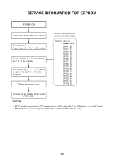
...(1~6 for a while) Use arrow key (F D G E) to move to approprite position and make changes Press pause key once DETECT NEW EEPROM (OPTION EDIT SCREEN) MODEL XBV613 NAME HEX OPT 1 55 OPT 2 53 OPT 3 00 OPT 4 45 OPT 5 12 OPT 6 05 OPT 7 E4 OPT 8 00 OPT 9 00 OPT A ... when power OFF-->ON. * OPTION • NTSC model doesn't have VCR option and use DVD option B~F as VCR option. (only DVD exist) • PAL model has another separate VCR option. (Both VCR and DVD exist) 1-5 SERVICE INFORMATION FOR EEPROM POWER ON DVD LOGO Status (NO Disk status) Remotecontrol Pause key-->1-->4-->7-->2 in order.
...(1~6 for a while) Use arrow key (F D G E) to move to approprite position and make changes Press pause key once DETECT NEW EEPROM (OPTION EDIT SCREEN) MODEL XBV613 NAME HEX OPT 1 55 OPT 2 53 OPT 3 00 OPT 4 45 OPT 5 12 OPT 6 05 OPT 7 E4 OPT 8 00 OPT 9 00 OPT A ... when power OFF-->ON. * OPTION • NTSC model doesn't have VCR option and use DVD option B~F as VCR option. (only DVD exist) • PAL model has another separate VCR option. (Both VCR and DVD exist) 1-5 SERVICE INFORMATION FOR EEPROM POWER ON DVD LOGO Status (NO Disk status) Remotecontrol Pause key-->1-->4-->7-->2 in order.
Service Manual
Page 7
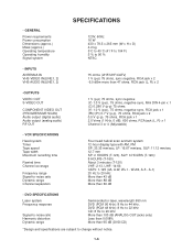
...LINE1, 2) 75 ohms (VHF/UHF/CATV) 1 V (p-p) 75 ohms, sync negative, RCA jack x 2 -6.0 dBm more than 95 dB (DVD/CD) *Design and specifications are subject to -noise ratio Dynamic range Channel separation Four head helical scan azimuth system 12-hour display type with AM... 0.7 V (p-p), 75 ohms, RCA jack x 2 0.5 V (p-p), 75 ohms, RCA jack x 1 2.0 Vrms (1 KHz, 0 dB), 600 ohms, RCA jack (L, R) x 1 Channel 3 or 4 (Adjustable) • VCR SPECIFICATIONS Head system Timer Tape speed Tape width Maximum recording time Rewind time Channel coverage Frequency range Signal-to change without notice. 1-6
...LINE1, 2) 75 ohms (VHF/UHF/CATV) 1 V (p-p) 75 ohms, sync negative, RCA jack x 2 -6.0 dBm more than 95 dB (DVD/CD) *Design and specifications are subject to -noise ratio Dynamic range Channel separation Four head helical scan azimuth system 12-hour display type with AM... 0.7 V (p-p), 75 ohms, RCA jack x 2 0.5 V (p-p), 75 ohms, RCA jack x 1 2.0 Vrms (1 KHz, 0 dB), 600 ohms, RCA jack (L, R) x 1 Channel 3 or 4 (Adjustable) • VCR SPECIFICATIONS Head system Timer Tape speed Tape width Maximum recording time Rewind time Channel coverage Frequency range Signal-to change without notice. 1-6
Service Manual
Page 12
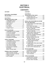
... CIRCUIT DIAGRAM 3-33 3. SYSTEM 27MHZ CLOCK, RESET SIGNAL ...3-65 2. SLED CONTROL RELATED SIGNAL (NO DISC CONDITION 3-68 5. DISC TYPE JUDGEMENT WAVEFORM.........3-69 8. SECTION 3 ELECTRICAL VCR PART CONTENTS DVD PART ELECTRICAL ADJUSTMENT PROCEDURES 3-2 ELECTRICAL TROUBLESHOOTING GUIDE 3-3 1. POWER(SMPS) CIRCUIT 3-3 2. SYSTEM OPERATION FLOW 3-58 3. TUNER/IF CIRCUIT 3-17 BLOCK DIAGRAMS 3-19 1. SYSTEM BLOCK DIAGRAM...
... CIRCUIT DIAGRAM 3-33 3. SYSTEM 27MHZ CLOCK, RESET SIGNAL ...3-65 2. SLED CONTROL RELATED SIGNAL (NO DISC CONDITION 3-68 5. DISC TYPE JUDGEMENT WAVEFORM.........3-69 8. SECTION 3 ELECTRICAL VCR PART CONTENTS DVD PART ELECTRICAL ADJUSTMENT PROCEDURES 3-2 ELECTRICAL TROUBLESHOOTING GUIDE 3-3 1. POWER(SMPS) CIRCUIT 3-3 2. SYSTEM OPERATION FLOW 3-58 3. TUNER/IF CIRCUIT 3-17 BLOCK DIAGRAMS 3-19 1. SYSTEM BLOCK DIAGRAM...
Service Manual
Page 13
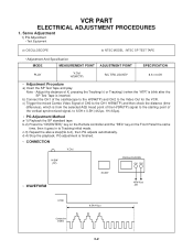
... on the Remote controller and the "REC" key on the Front Panel the same time, then it goes in to the Video Out for the VCR. VCR PART ELECTRICAL ADJUSTMENT PROCEDURES 1.
... on the Remote controller and the "REC" key on the Front Panel the same time, then it goes in to the Video Out for the VCR. VCR PART ELECTRICAL ADJUSTMENT PROCEDURES 1.
Service Manual
Page 35
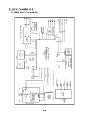
... + CTL DPG CFG CAP. H.SW 19 A. MUTE 'H' 68 REC 'H' 74 CLK 71 DATA 72 CV OUT 52 AFT 100 PLL CLK 71 PLL DATA 72 VCR 'H' 26 MODU CTL 61 TO/FROM AUDIO(Hi-Fi) Hi-Fi ONLY TO/ FROM TU/IF OSC in 66 OSC S out 65... DVD DATA OUT 65 DVD DATA IN 66 DVD CLK 67 DVD RESET 82 DVD ENA 85 IC5F1 TO/FROM DVD IC501 M37760 A. ENV 8 A. REV 'H' LD CTL V. 6. SYSTEM BLOCK DIAGRAM TO/FROM DECK TO/FROM AVCP MODE S/W 5.3VA...
... + CTL DPG CFG CAP. H.SW 19 A. MUTE 'H' 68 REC 'H' 74 CLK 71 DATA 72 CV OUT 52 AFT 100 PLL CLK 71 PLL DATA 72 VCR 'H' 26 MODU CTL 61 TO/FROM AUDIO(Hi-Fi) Hi-Fi ONLY TO/ FROM TU/IF OSC in 66 OSC S out 65... DVD DATA OUT 65 DVD DATA IN 66 DVD CLK 67 DVD RESET 82 DVD ENA 85 IC5F1 TO/FROM DVD IC501 M37760 A. ENV 8 A. REV 'H' LD CTL V. 6. SYSTEM BLOCK DIAGRAM TO/FROM DECK TO/FROM AVCP MODE S/W 5.3VA...
Service Manual
Page 71
... OPTION MIIC_DET L AIN IC607 CS5331A R AM CL K AB CLK ALRCLK RFV33/DV33/1.8V MIC_IN KA RAOKE 5V MC IC605 KS24C021CS EEPROM MD DVD:RF,A,B,C,D CD:RF,A,B,C,D,E,F DVD_LD,CD_LD, V C PICKSEL HOMESW OUTSW , INSW OPEN, CLOSE DRVSB,TRACK_S,FOCUS_S,SLED_S SPINDLE_S MOTOR_VCC REG_12V REG_9V 8V ...3.3V PWR_CTL_H 33V 5.3VA 5.0V M5V/5VT IC601 ZR36882ELCG DSP/MPEG/RF VCR_DATA DVD_RESET 27MHz X-TAL DVD_ENA* DVD_CLK DVD_DATA* IC501 MN101DF10G VCR MICOM 5V/REG12V IC801 TDA9605H HIFI MUTE_C MUTE CIRCUIT AL PCLK , AB CLK AMCLK , AOUTO A_L +/- A_R +/- 3-78 FACT+/-,TACTT +/MOT_SPDL ...
... OPTION MIIC_DET L AIN IC607 CS5331A R AM CL K AB CLK ALRCLK RFV33/DV33/1.8V MIC_IN KA RAOKE 5V MC IC605 KS24C021CS EEPROM MD DVD:RF,A,B,C,D CD:RF,A,B,C,D,E,F DVD_LD,CD_LD, V C PICKSEL HOMESW OUTSW , INSW OPEN, CLOSE DRVSB,TRACK_S,FOCUS_S,SLED_S SPINDLE_S MOTOR_VCC REG_12V REG_9V 8V ...3.3V PWR_CTL_H 33V 5.3VA 5.0V M5V/5VT IC601 ZR36882ELCG DSP/MPEG/RF VCR_DATA DVD_RESET 27MHz X-TAL DVD_ENA* DVD_CLK DVD_DATA* IC501 MN101DF10G VCR MICOM 5V/REG12V IC801 TDA9605H HIFI MUTE_C MUTE CIRCUIT AL PCLK , AB CLK AMCLK , AOUTO A_L +/- A_R +/- 3-78 FACT+/-,TACTT +/MOT_SPDL ...
Service Manual
Page 78
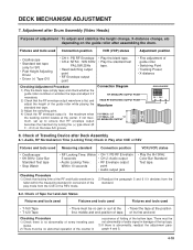
... Play after Drum Assembly (Video Heads 4-18 8. Checking Points before Repair 4-19 2. Essential Check and Repair 4-20 3. Tools for Deck Adjustment 4-14 3. SECTION 4 MECHANISM OF VCR PART(D-37) CONTENTS DECK MECHANISM PARTS LOCATIONS • Top View 4-1 • Bottom View 4-1 DISASSEMBLY AND ASSEMBLY OF DECK MECHANISM 01.Disassembly of Drum assembly 4-2 02...
... Play after Drum Assembly (Video Heads 4-18 8. Checking Points before Repair 4-19 2. Essential Check and Repair 4-20 3. Tools for Deck Adjustment 4-14 3. SECTION 4 MECHANISM OF VCR PART(D-37) CONTENTS DECK MECHANISM PARTS LOCATIONS • Top View 4-1 • Bottom View 4-1 DISASSEMBLY AND ASSEMBLY OF DECK MECHANISM 01.Disassembly of Drum assembly 4-2 02...

Service Manual
Page 91
...) status Checking Position • Blank Tape (empty tape) • Eject Mode (with cassette withdrawn) • Mechanism and Mode Switch 1) Turn the VCR on the main P.C. board locates at a proper position as in (B) of chassis correspond (Fig. board and perform all types of the gear cam hole (O) and ...
...) status Checking Position • Blank Tape (empty tape) • Eject Mode (with cassette withdrawn) • Mechanism and Mode Switch 1) Turn the VCR on the main P.C. board locates at a proper position as in (B) of chassis correspond (Fig. board and perform all types of the gear cam hole (O) and ...
Service Manual
Page 92
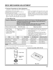
...-O3ATR0ES3QVRSIUESDETERTOEK SRK - C-3-1) • Read scale of the supply or take -up reel remains at stop mode is abnormally proceeded: Fixtures and tools used VCR (VCP) status Measuring method • Torque Gauge (600 g.cm ATG) • Torque Gauge Adaptor • Cassette Torque Meter SRK-VHT-303 &#...cannot detect the reel pulse (however, possible for Deck Adjustment). • Measure after adhering and fixing the torque gauge adaptor to operate the VCR (VCP) per mode with cassette tape not inserted) 1) Take the power cord from the consent. 2) Separate the top cover and the...
...-O3ATR0ES3QVRSIUESDETERTOEK SRK - C-3-1) • Read scale of the supply or take -up reel remains at stop mode is abnormally proceeded: Fixtures and tools used VCR (VCP) status Measuring method • Torque Gauge (600 g.cm ATG) • Torque Gauge Adaptor • Cassette Torque Meter SRK-VHT-303 &#...cannot detect the reel pulse (however, possible for Deck Adjustment). • Measure after adhering and fixing the torque gauge adaptor to operate the VCR (VCP) per mode with cassette tape not inserted) 1) Take the power cord from the consent. 2) Separate the top cover and the...
Service Manual
Page 93
.... Prior Adjustment Fixtures and tools used • Oscilloscope • Standard test tape • Post height adjusting driver Measuring tools and connection position VCR (VCP) status • CH-1: PB RF Envelope • Play the standard test • CH-2: NTSC : SW 30Hz tape. C-4-3) ...C-4-2 Flatten the waveform by constantly and adjusting and maintaining the height of the drum. (Fig. Fine Adjustment Fixtures and tools used VCR (VCP) status Adjustment position • Post Height Adjusting Driver • Play or Review Mode Adjustment Procedure 1) Travel the tape and...
.... Prior Adjustment Fixtures and tools used • Oscilloscope • Standard test tape • Post height adjusting driver Measuring tools and connection position VCR (VCP) status • CH-1: PB RF Envelope • Play the standard test • CH-2: NTSC : SW 30Hz tape. C-4-3) ...C-4-2 Flatten the waveform by constantly and adjusting and maintaining the height of the drum. (Fig. Fine Adjustment Fixtures and tools used VCR (VCP) status Adjustment position • Post Height Adjusting Driver • Play or Review Mode Adjustment Procedure 1) Travel the tape and...
Service Manual
Page 94
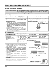
... (C) • Height adjusting screw (B) • Azimuth adjusting screw (A) 3) Where the tape bottom is crumpling and folding of the standard test tape) Fixtures and tools used VCR (VCP) status Adjustment position • Blank Tape (Empty Tape) • Driver (+) Type ø 5 • Play the blank tape (empty tape). CAUTIONS Always check the height...
... (C) • Height adjusting screw (B) • Azimuth adjusting screw (A) 3) Where the tape bottom is crumpling and folding of the standard test tape) Fixtures and tools used VCR (VCP) status Adjustment position • Blank Tape (Empty Tape) • Driver (+) Type ø 5 • Play the blank tape (empty tape). CAUTIONS Always check the height...

Service Manual
Page 95
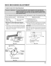
Fixtures and tools used Connection position VCR (VCP) status Adjustment position • Oscilloscope • Standard test tape (only for SP) • Driver (+) Type Ø 4 • Audio Output Jack Adjustment Procedure...the standard test • CH-2: NTSC ; Fine Adjustment (Azimuth Adjustment) Fixtures and tools used Connection position VCR (VCP) status Adjustment position • Oscilloscope • Standard test tape (only for SP with other VCR (VCP). SW 30Hz tape. Connection Diagram X-distance Adjusting Hole Fixing Screw Azimuth Adjustment Screw(A) Fig. DECK ...
Fixtures and tools used Connection position VCR (VCP) status Adjustment position • Oscilloscope • Standard test tape (only for SP) • Driver (+) Type Ø 4 • Audio Output Jack Adjustment Procedure...the standard test • CH-2: NTSC ; Fine Adjustment (Azimuth Adjustment) Fixtures and tools used Connection position VCR (VCP) status Adjustment position • Oscilloscope • Standard test tape (only for SP with other VCR (VCP). SW 30Hz tape. Connection Diagram X-distance Adjusting Hole Fixing Screw Azimuth Adjustment Screw(A) Fig. DECK ...
Service Manual
Page 96
...the maximum by turning the (+) type driver (Ø 3 ~ Ø 4) on the guide roller after CUE or REV Fixtures and tools used Connection position VCR (VCP) status Adjustment position • Oscilloscope • Standard test tape (only for SP) • Post Height Adjusting Driver • Driver (+) Type &#...There must be no jam or curl at the • Travel the tape at the center. Fixtures and tools used Measuring standard Connection position VCR (VCP) status • Oscilloscope • 6H 3KHz Color Bar Standard Test tape • Stop Watch • RF Locking Time: Within...
...the maximum by turning the (+) type driver (Ø 3 ~ Ø 4) on the guide roller after CUE or REV Fixtures and tools used Connection position VCR (VCP) status Adjustment position • Oscilloscope • Standard test tape (only for SP) • Post Height Adjusting Driver • Driver (+) Type &#...There must be no jam or curl at the • Travel the tape at the center. Fixtures and tools used Measuring standard Connection position VCR (VCP) status • Oscilloscope • 6H 3KHz Color Bar Standard Test tape • Stop Watch • RF Locking Time: Within...

Service Manual
Page 110
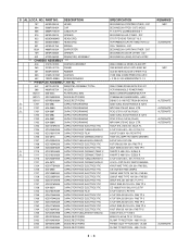
... 5 REPLACEMENT PARTS LIST MODEL : XBV613(LGEUS) S AL LOCA. NA1ULZ SWM3-A LGEUSZE VCR COMBIV9 130 COMBI SOFT(MIDI) AAAM(R03) SEOTONG 1-5 V - 1PA N6 V1310MZ.NA1ULZ ZENITH NSP VCR V1310MZ NA1ULZ ZENITH 2006 VCR V1310MZ NA1ULZ MOLD ZENITH VCR V1310MZ NA1ULZ MOLD HF-380 DOOR VCR V1310MZ NA1ULZ MOLD HF-380 PLATE ... 2 D3.0 L10.0 MSWR3/FZB 3 CR + 2 D3.0 L6.5 MSWR3/FZMCY-1 3 + 2 D3.0 21MM MSWR3/FZMCY-1 3C + 2 D3.0 L16.0 MSWR3/FN SILVER VCR V1310MZ.NA1ULZ V1310MZ. NOTES) If you want to purchase Flash memory, you must order " IC604A " NOTES) Warning Parts that are shaded are critical with respect...
... 5 REPLACEMENT PARTS LIST MODEL : XBV613(LGEUS) S AL LOCA. NA1ULZ SWM3-A LGEUSZE VCR COMBIV9 130 COMBI SOFT(MIDI) AAAM(R03) SEOTONG 1-5 V - 1PA N6 V1310MZ.NA1ULZ ZENITH NSP VCR V1310MZ NA1ULZ ZENITH 2006 VCR V1310MZ NA1ULZ MOLD ZENITH VCR V1310MZ NA1ULZ MOLD HF-380 DOOR VCR V1310MZ NA1ULZ MOLD HF-380 PLATE ... 2 D3.0 L10.0 MSWR3/FZB 3 CR + 2 D3.0 L6.5 MSWR3/FZMCY-1 3 + 2 D3.0 21MM MSWR3/FZMCY-1 3C + 2 D3.0 L16.0 MSWR3/FN SILVER VCR V1310MZ.NA1ULZ V1310MZ. NOTES) If you want to purchase Flash memory, you must order " IC604A " NOTES) Warning Parts that are shaded are critical with respect...
Service Manual
Page 112
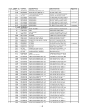
... MOLD HIPS 403AF BK CCD 05 NEW SILICON OTHER 2T (3 V10S 2006 COMBI PRESS RCA W/O + 2 D3.0 L10.0 MSWR3/FZMCY-1 3 2006 COMBI ZORAN WITH DIVX NT VCR V9500 MOLD POWER PWB BEAD CORE BFS3550R2FD8,R T/P S1WBA60 BK SHINDENGEN - 600V DB105-C-S-V50 RECTRON BK NON 6 435D SUNIL ELECTRONICS 0.1UF/2 MPX104K 275VAC BULK ETR PCX2...
... MOLD HIPS 403AF BK CCD 05 NEW SILICON OTHER 2T (3 V10S 2006 COMBI PRESS RCA W/O + 2 D3.0 L10.0 MSWR3/FZMCY-1 3 2006 COMBI ZORAN WITH DIVX NT VCR V9500 MOLD POWER PWB BEAD CORE BFS3550R2FD8,R T/P S1WBA60 BK SHINDENGEN - 600V DB105-C-S-V50 RECTRON BK NON 6 435D SUNIL ELECTRONICS 0.1UF/2 MPX104K 275VAC BULK ETR PCX2...
Service Manual
Page 114
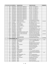
NO. PRE AMP SLIM COMBI C-CORE A NO VCR ONE BOARD SLIM MOLD HIPS 6 COMBI-P NTSC 2006 ZV1002020010 00-6232-023-006-800 ELCO 23PIN 00-6232-009-006-800 ELCO 9P 1JE117-D22T-... PYUNG CHANG GDZJ13A 26MM TP GRANDE DO34 0 UZ-13BSA 26MM TP PYUNG CHANG UZ-10BSB 26MM TP PYUNG CHANG D UZ-10BM TP PYUNG CHANG - 0.5W VCR V1310MZ.NA1ULZ MAIN BOARD SHIELD(SLIM-COMBI) PRESS . PART NO. S AL LOCA.
NO. PRE AMP SLIM COMBI C-CORE A NO VCR ONE BOARD SLIM MOLD HIPS 6 COMBI-P NTSC 2006 ZV1002020010 00-6232-023-006-800 ELCO 23PIN 00-6232-009-006-800 ELCO 9P 1JE117-D22T-... PYUNG CHANG GDZJ13A 26MM TP GRANDE DO34 0 UZ-13BSA 26MM TP PYUNG CHANG UZ-10BSB 26MM TP PYUNG CHANG D UZ-10BM TP PYUNG CHANG - 0.5W VCR V1310MZ.NA1ULZ MAIN BOARD SHIELD(SLIM-COMBI) PRESS . PART NO. S AL LOCA.
Service Manual
Page 127
...DP-10C LOADING/FEEDING DP-10C FEEDING (MTK 1389E, ZOR P=1.0 FFC UL2896(0.035X0.7) 23 DECK/MECHA DP-10 FEEDING DVD DP-9 PINION MOLD DVD DP-9 MIDDLE MOLD DVD DP-9 RACK MOLD DVD PU, DR-02 SUS-420J2 OTHER REMARKS ALTERNATE ALTERNATE ALTERNATE ALTERNATE NSP NSP 5 - 18 PART NO. DESCRIPTION R901 ...579545MHZ +/ HC-49/SM CSC(SSANGTAI) 3.57954 MA V 8283-0212 WH ELCO MPU12970MLB0 VCR CST IN S/W MI VCR DECK/MECHA END(S) VCR DECK/MECHA END(S) M3776AMCH-1D6GP 3RD RENESAS 10 DPAE-0385 DOOWON RGB 2004 CO VCR DECK/MECHA END(S) TOS-366AGMGMRMY-B OASIS UNIVER SSS-51MD-3 SHINMEI 5VDC 1MA D3 MMS01080ZMBO...
...DP-10C LOADING/FEEDING DP-10C FEEDING (MTK 1389E, ZOR P=1.0 FFC UL2896(0.035X0.7) 23 DECK/MECHA DP-10 FEEDING DVD DP-9 PINION MOLD DVD DP-9 MIDDLE MOLD DVD DP-9 RACK MOLD DVD PU, DR-02 SUS-420J2 OTHER REMARKS ALTERNATE ALTERNATE ALTERNATE ALTERNATE NSP NSP 5 - 18 PART NO. DESCRIPTION R901 ...579545MHZ +/ HC-49/SM CSC(SSANGTAI) 3.57954 MA V 8283-0212 WH ELCO MPU12970MLB0 VCR CST IN S/W MI VCR DECK/MECHA END(S) VCR DECK/MECHA END(S) M3776AMCH-1D6GP 3RD RENESAS 10 DPAE-0385 DOOWON RGB 2004 CO VCR DECK/MECHA END(S) TOS-366AGMGMRMY-B OASIS UNIVER SSS-51MD-3 SHINMEI 5VDC 1MA D3 MMS01080ZMBO...


