Owner's Manual
Page 5
...control features 96 Setting remote control codes 96 Controlling other external components 27 Connecting a subwoofer 28 Connecting the FM antenna 29 About the IR IN terminal (U.S.A. and Canada models)... a TV 22 Connecting a DVD player/recorder 23 Connecting a digital satellite tuner or a cable TV tuner 24 Connecting a digital airwave tuner 25 Connecting a portable audio player 26 Connecting other ...tuning 51 Selecting a preset station 52 Displaying the Radio Data System information (Europe model only 52 Enjoying surround sound 54 5 Beam 54 Stereo plus 3 Beam 55 3 Beam 55 ...
...control features 96 Setting remote control codes 96 Controlling other external components 27 Connecting a subwoofer 28 Connecting the FM antenna 29 About the IR IN terminal (U.S.A. and Canada models)... a TV 22 Connecting a DVD player/recorder 23 Connecting a digital satellite tuner or a cable TV tuner 24 Connecting a digital airwave tuner 25 Connecting a portable audio player 26 Connecting other ...tuning 51 Selecting a preset station 52 Displaying the Radio Data System information (Europe model only 52 Enjoying surround sound 54 5 Beam 54 Stereo plus 3 Beam 55 3 Beam 55 ...
Owner's Manual
Page 7
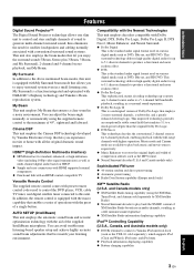
..., a subwoofer, and a greatly enhanced steering logic. You can adjust the beam angle manually or automatically using the XM MiniTuner Dock, and Antenna sold separately), which supports iPod (Click and Wheel), iPod nano, and iPod mini ◆ Playback information displaying capability ◆ Battery charging capability English 3 En INTRODUCTION Features Features Digital Sound Projector™ The Digital Sound Projector...
..., a subwoofer, and a greatly enhanced steering logic. You can adjust the beam angle manually or automatically using the XM MiniTuner Dock, and Antenna sold separately), which supports iPod (Click and Wheel), iPod nano, and iPod mini ◆ Playback information displaying capability ◆ Battery charging capability English 3 En INTRODUCTION Features Features Digital Sound Projector™ The Digital Sound Projector...
Owner's Manual
Page 10
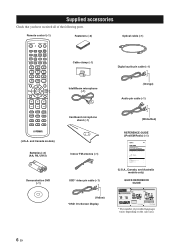
...Home Dock 5 Activating XM Satellite Radio ...6 Basic XM Satellite Radio operations ...6 Presetting the XM Satellite Radio channels 9 Displaying the XM Satellite Radio information 10 Troubleshooting ...11 (U.S.A., Canada, and Australia models only) QUICK REFERENCE GUIDE YSP-3000... connection AUX 1 DVD IN OUT HDMI AUDIO INPUT OUT VIDEO DIGITAL INPUT AUX 2 DVD COAXIAL YSP-3000 AUX 1 TV/STB SUBWOOFER AUX 1 TV/STB Subwoofer Audio connection * The rear panel illustration shows jacks and their ... Yamaha YSP-3000 Digital Sound Projector. For details, see pages 19 to rack.
...Home Dock 5 Activating XM Satellite Radio ...6 Basic XM Satellite Radio operations ...6 Presetting the XM Satellite Radio channels 9 Displaying the XM Satellite Radio information 10 Troubleshooting ...11 (U.S.A., Canada, and Australia models only) QUICK REFERENCE GUIDE YSP-3000... connection AUX 1 DVD IN OUT HDMI AUDIO INPUT OUT VIDEO DIGITAL INPUT AUX 2 DVD COAXIAL YSP-3000 AUX 1 TV/STB SUBWOOFER AUX 1 TV/STB Subwoofer Audio connection * The rear panel illustration shows jacks and their ... Yamaha YSP-3000 Digital Sound Projector. For details, see pages 19 to rack.
Owner's Manual
Page 13
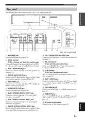
... AUX 1 TV/STB SUBWOOFER DIGITAL INPUT AUX 2 DVD COAXIAL OPTICAL AUX 1 TV/STB XM IR IN AUX 1 C DVD D IN E OUT HDMI 12 3 4 5 6 78 1 ANTENNA jack Connect the FM antenna (see page 29). 2 DOCK terminal (U.S.A., Canada, and Australia models only) Connect the Yamaha iPod universal dock (such as a TV or a projector connected to display the...
... AUX 1 TV/STB SUBWOOFER DIGITAL INPUT AUX 2 DVD COAXIAL OPTICAL AUX 1 TV/STB XM IR IN AUX 1 C DVD D IN E OUT HDMI 12 3 4 5 6 78 1 ANTENNA jack Connect the FM antenna (see page 29). 2 DOCK terminal (U.S.A., Canada, and Australia models only) Connect the Yamaha iPod universal dock (such as a TV or a projector connected to display the...
Owner's Manual
Page 23
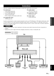
... 2 sets of external components to this unit, see pages 21 to 28. Further, by connecting a subwoofer to this unit. Audio connection Video connection TV This unit English DVD player Subwoofer portable audio player Digital satellite tuner or cable TV tuner VCR or game console 19 En For details on how to... complete. • Unplug the AC power supply cable before changing connections, moving or cleaning this unit, you can enjoy reinforced low-bass sounds. CAUTION • Do not connect this unit or other components to connect external components such as your TV, DVD player, VCR...
... 2 sets of external components to this unit, see pages 21 to 28. Further, by connecting a subwoofer to this unit. Audio connection Video connection TV This unit English DVD player Subwoofer portable audio player Digital satellite tuner or cable TV tuner VCR or game console 19 En For details on how to... complete. • Unplug the AC power supply cable before changing connections, moving or cleaning this unit, you can enjoy reinforced low-bass sounds. CAUTION • Do not connect this unit or other components to connect external components such as your TV, DVD player, VCR...
Owner's Manual
Page 24
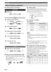
.../Video A HDMI cable Audio Audio pin cable (supplied) (White) (Red) Optical cable (supplied) (White) (Red) Digital audio pin cable (supplied) (Orange) (Orange) 3.5 mm stereo mini plug cable 5 Subwoofer pin cable Video OSD video pin cable (supplied) (Yellow) (Yellow) ■ Notes on it to the rear panel... source component, this unit in a suitable position, and then affix cables in place. • When inserting the cable into the optical digital jack, make sure the direction is not compatible with the HDMI logo printed on connecting the optical cable • Pull out the cap ...
.../Video A HDMI cable Audio Audio pin cable (supplied) (White) (Red) Optical cable (supplied) (White) (Red) Digital audio pin cable (supplied) (Orange) (Orange) 3.5 mm stereo mini plug cable 5 Subwoofer pin cable Video OSD video pin cable (supplied) (Yellow) (Yellow) ■ Notes on it to the rear panel... source component, this unit in a suitable position, and then affix cables in place. • When inserting the cable into the optical digital jack, make sure the direction is not compatible with the HDMI logo printed on connecting the optical cable • Pull out the cap ...
Owner's Manual
Page 25
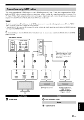
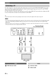
... the HDMI jack, you need to connect the video input jack on this unit in order to display the OSD of this unit OUT VIDEO SUBWOOFER DIGITAL INPUT AUX 2 DVD COAXIAL OPTICAL AUX 1 TV/STB AUX 1 DVD IN OUT HDMI * This connection (except for simpler and easier connections, and you have HDMI... tuner, or game console Video OSD video pin cable Audio Optical cable 21 En English If your TV to the TV/STB OPTICAL DIGITAL INPUT jack on your TV and other components have connected the HDMI cable(s) to the HDMI jack(s) of this unit. • When HDMI CONTROL is ...
... the HDMI jack, you need to connect the video input jack on this unit in order to display the OSD of this unit OUT VIDEO SUBWOOFER DIGITAL INPUT AUX 2 DVD COAXIAL OPTICAL AUX 1 TV/STB AUX 1 DVD IN OUT HDMI * This connection (except for simpler and easier connections, and you have HDMI... tuner, or game console Video OSD video pin cable Audio Optical cable 21 En English If your TV to the TV/STB OPTICAL DIGITAL INPUT jack on your TV and other components have connected the HDMI cable(s) to the HDMI jack(s) of this unit. • When HDMI CONTROL is ...
Owner's Manual
Page 26
... video input jack on your TV to the VIDEO OUT jack on this unit to display the OSD for easy viewing when you adjust the system parameters in SET MENU. Rear panel of this unit. For video connection, connect the video input jack on your TV to the VIDEO OUT jack... on your TV to the TV/STB AUDIO INPUT jacks on this unit. and Canada models) ANTENNA AUDIO INPUT OUT VIDEO DOCK AUX 1 TV/STB SUBWOOFER DIGITAL INPUT AUX 2 DVD COAXIAL OPTICAL AUX 1 TV/STB XM IR IN R L Analog audio output Video input Optical...
... video input jack on your TV to the VIDEO OUT jack on this unit to display the OSD for easy viewing when you adjust the system parameters in SET MENU. Rear panel of this unit. For video connection, connect the video input jack on your TV to the VIDEO OUT jack... on your TV to the TV/STB AUDIO INPUT jacks on this unit. and Canada models) ANTENNA AUDIO INPUT OUT VIDEO DOCK AUX 1 TV/STB SUBWOOFER DIGITAL INPUT AUX 2 DVD COAXIAL OPTICAL AUX 1 TV/STB XM IR IN R L Analog audio output Video input Optical...
Owner's Manual
Page 27
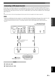
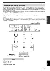
.../recorder English 23 En Rear panel of your DVD player/recorder. If not, adjust the system settings of this unit. and Canada models) ANTENNA AUDIO INPUT OUT VIDEO DOCK AUX 1 TV/STB SUBWOOFER DIGITAL INPUT AUX 2 DVD COAXIAL OPTICAL AUX 1 TV/STB XM IR IN * For the... DVD/VCR combo player/recorder connection R L Analog audio output Coaxial digital output Video signal to the operation manual supplied with your DVD player...
.../recorder English 23 En Rear panel of your DVD player/recorder. If not, adjust the system settings of this unit. and Canada models) ANTENNA AUDIO INPUT OUT VIDEO DOCK AUX 1 TV/STB SUBWOOFER DIGITAL INPUT AUX 2 DVD COAXIAL OPTICAL AUX 1 TV/STB XM IR IN * For the... DVD/VCR combo player/recorder connection R L Analog audio output Coaxial digital output Video signal to the operation manual supplied with your DVD player...
Owner's Manual
Page 28
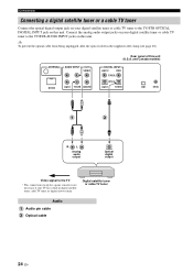
... TV/STB SUBWOOFER Rear panel of this unit. and Canada models) DIGITAL INPUT AUX 2 DVD COAXIAL OPTICAL AUX 1 TV/STB XM IR IN R L Analog audio output Optical digital output Video signal to the TV * This connection (except for a game console) is not necessary if your digital satellite tuner ... (see page 20). y To prevent the optical cable from being unplugged, affix the optical cable in digital satellite tuner, cable TV tuner, or digital airwave tuner. Digital satellite tuner or cable TV tuner Audio Audio pin cable Optical cable 24 En Connect the analog audio output...
... TV/STB SUBWOOFER Rear panel of this unit. and Canada models) DIGITAL INPUT AUX 2 DVD COAXIAL OPTICAL AUX 1 TV/STB XM IR IN R L Analog audio output Optical digital output Video signal to the TV * This connection (except for a game console) is not necessary if your digital satellite tuner ... (see page 20). y To prevent the optical cable from being unplugged, affix the optical cable in digital satellite tuner, cable TV tuner, or digital airwave tuner. Digital satellite tuner or cable TV tuner Audio Audio pin cable Optical cable 24 En Connect the analog audio output...
Owner's Manual
Page 29
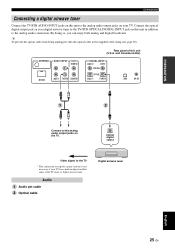
...the optical cable from being unplugged, affix the optical cable in digital satellite tuner, cable TV tuner, or digital airwave tuner. ANTENNA AUDIO INPUT OUT VIDEO DOCK AUX 1 TV/STB SUBWOOFER Rear panel of this unit (U.S.A. and Canada models) DIGITAL INPUT AUX 2 DVD COAXIAL OPTICAL AUX 1 TV/STB XM ...IR IN PREPARATION Connect to the analog audio output jacks on your TV. Optical digital output Video signal to the TV * ...
...the optical cable from being unplugged, affix the optical cable in digital satellite tuner, cable TV tuner, or digital airwave tuner. ANTENNA AUDIO INPUT OUT VIDEO DOCK AUX 1 TV/STB SUBWOOFER Rear panel of this unit (U.S.A. and Canada models) DIGITAL INPUT AUX 2 DVD COAXIAL OPTICAL AUX 1 TV/STB XM ...IR IN PREPARATION Connect to the analog audio output jacks on your TV. Optical digital output Video signal to the TV * ...
Owner's Manual
Page 31
... jack on this unit (U.S.A. Note If you make analog and digital audio connections at the same time as shown in the supplied cable clamp (see page 20). ANTENNA AUDIO INPUT OUT VIDEO DOCK AUX 1 TV/STB SUBWOOFER Rear panel of this unit. y To prevent the optical cable from being ...unplugged, affix the optical cable in the illustration below, the digital audio signals input at the AUX 1 OPTICAL DIGITAL INPUT or AUX 2 COAXIAL DIGITAL INPUT jack take priority over the analog ...
... jack on this unit (U.S.A. Note If you make analog and digital audio connections at the same time as shown in the supplied cable clamp (see page 20). ANTENNA AUDIO INPUT OUT VIDEO DOCK AUX 1 TV/STB SUBWOOFER Rear panel of this unit. y To prevent the optical cable from being ...unplugged, affix the optical cable in the illustration below, the digital audio signals input at the AUX 1 OPTICAL DIGITAL INPUT or AUX 2 COAXIAL DIGITAL INPUT jack take priority over the analog ...
Owner's Manual
Page 32
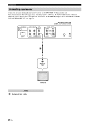
... DOCK AUX 1 TV/STB SUBWOOFER Rear panel of your subwoofer and then run AUTO SETUP (see page 35) or select SWFR for BASS OUT in SUBWOOFER SET (see page 78). To output sound from the connected subwoofer. and Canada models) DIGITAL INPUT AUX 2 DVD COAXIAL ...OPTICAL AUX 1 TV/STB XM IR IN 5 Monaural input Audio 5 Subwoofer pin cable Subwoofer 28 En Connections Connecting a subwoofer Connect the monaural input jack on your subwoofer to the SUBWOOFER...
... DOCK AUX 1 TV/STB SUBWOOFER Rear panel of your subwoofer and then run AUTO SETUP (see page 35) or select SWFR for BASS OUT in SUBWOOFER SET (see page 78). To output sound from the connected subwoofer. and Canada models) DIGITAL INPUT AUX 2 DVD COAXIAL ...OPTICAL AUX 1 TV/STB XM IR IN 5 Monaural input Audio 5 Subwoofer pin cable Subwoofer 28 En Connections Connecting a subwoofer Connect the monaural input jack on your subwoofer to the SUBWOOFER...
Owner's Manual
Page 33
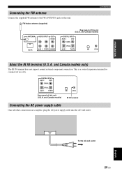
and Canada models) DIGITAL INPUT AUX 2 DVD COAXIAL OPTICAL AUX 1 TV/STB XM IR IN About the IR IN terminal (U.S.A. and Canada models... power supply cable into the AC wall outlet. and Canada models only) The IR IN terminal does not support normal external component connection. DIGITAL INPUT AUX 2 DVD COAXIAL OPTICAL AUX 1 TV/STB Rear panel of this unit (U.S.A. This is a control expansion terminal for commercial use... AC wall outlet 29 En FM indoor antenna (supplied) Connections ANTENNA AUDIO INPUT OUT VIDEO DOCK AUX 1 TV/STB SUBWOOFER Rear panel of this unit.
and Canada models) DIGITAL INPUT AUX 2 DVD COAXIAL OPTICAL AUX 1 TV/STB XM IR IN About the IR IN terminal (U.S.A. and Canada models... power supply cable into the AC wall outlet. and Canada models only) The IR IN terminal does not support normal external component connection. DIGITAL INPUT AUX 2 DVD COAXIAL OPTICAL AUX 1 TV/STB Rear panel of this unit (U.S.A. This is a control expansion terminal for commercial use... AC wall outlet 29 En FM indoor antenna (supplied) Connections ANTENNA AUDIO INPUT OUT VIDEO DOCK AUX 1 TV/STB SUBWOOFER Rear panel of this unit.
Owner's Manual
Page 39
...and quality. Just as you would arrange the speaker position of other audio systems, you to enjoy the best possible sound from this unit. This unit employs the beam optimization and sound optimization features with the aid of the supplied IntelliBeam microphone, allowing you need... if BEAM OPTIMZ only is selected. *3 The subwoofer checking procedure is skipped if BEAM OPTIMZ only is selected. *2 *3 Checking the subwoofer and optimizing the beam delay, frequency, and volume Sound optimization SETUP English 35 En Sound optimization: This feature optimizes the beam delay, volume...
...and quality. Just as you would arrange the speaker position of other audio systems, you to enjoy the best possible sound from this unit. This unit employs the beam optimization and sound optimization features with the aid of the supplied IntelliBeam microphone, allowing you need... if BEAM OPTIMZ only is selected. *3 The subwoofer checking procedure is skipped if BEAM OPTIMZ only is selected. *2 *3 Checking the subwoofer and optimizing the beam delay, frequency, and volume Sound optimization SETUP English 35 En Sound optimization: This feature optimizes the beam delay, volume...

Owner's Manual
Page 40
Notes • After you can manually fine-tune the sound beam angle and balance the sound beam output levels using MANUAL SETUP (see page 72) once the AUTO SETUP procedure is completed. • If a subwoofer with adjustable volume and crossover/high-cut frequency to heat. - However, if this ... microphone. • The IntelliBeam microphone is sensitive to the maximum. MIN MAX MIN MAX Subwoofer 1 Press STANDBY/ON to an extension cable as doing so may result in an inaccurate sound optimization. • An error may want to use the supplied cardboard microphone stand to the...
Notes • After you can manually fine-tune the sound beam angle and balance the sound beam output levels using MANUAL SETUP (see page 72) once the AUTO SETUP procedure is completed. • If a subwoofer with adjustable volume and crossover/high-cut frequency to heat. - However, if this ... microphone. • The IntelliBeam microphone is sensitive to the maximum. MIN MAX MIN MAX Subwoofer 1 Press STANDBY/ON to an extension cable as doing so may result in an inaccurate sound optimization. • An error may want to use the supplied cardboard microphone stand to the...
Owner's Manual
Page 42
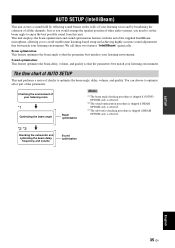
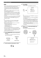
...;AUTO SETUP ;MANUAL SETUP ;LANGUAGE SETUP [ ]/[ ]:Up/Down [ENTER]:Enter y • The control buttons used for appropriate remedies. If a subwoofer is connected to this unit, turn on the varying conditions of your listening environment can save the settings optimized by pressing and holding AUTO SETUP...takes about three minutes maximum. Run BEAM OPTIMZ only. 3. ENTER ENTER ;AUTO SETUP . 1)BEAM+SOUND OPTIMZ 2)BEAM OPTIMZ only 3)SOUND OPTIMZ only [ ]/[ ]:Up/Down [ENTER]:Enter p p TV/AV YSP 38 En A chime is played when the AUTO SETUP procedure is run successfully. • If ...
...;AUTO SETUP ;MANUAL SETUP ;LANGUAGE SETUP [ ]/[ ]:Up/Down [ENTER]:Enter y • The control buttons used for appropriate remedies. If a subwoofer is connected to this unit, turn on the varying conditions of your listening environment can save the settings optimized by pressing and holding AUTO SETUP...takes about three minutes maximum. Run BEAM OPTIMZ only. 3. ENTER ENTER ;AUTO SETUP . 1)BEAM+SOUND OPTIMZ 2)BEAM OPTIMZ only 3)SOUND OPTIMZ only [ ]/[ ]:Up/Down [ENTER]:Enter p p TV/AV YSP 38 En A chime is played when the AUTO SETUP procedure is run successfully. • If ...
Owner's Manual
Page 44
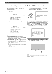
... and right may not be set up . [RETURN]:Do not save and load settings, see "Using the system memory" on the front panel. Example 1 SHOW RESULT MEASUREMENT COMPLETE ← Flashes BEAM MODE :5 BEAM SUBWOOFER :NOT APPLICABLE [ENTER]:Save set-up. [RETURN]:Do not save set -up . y If you try ... [ENTER]:Save set-up correctly. In this unit, increase the volume level of the subwoofer and run the procedure again from the YSP and the listening position. AUTO SETUP COMPLETE Your YSP unit may be set to exit AUTO SETUP and then run the AUTO SETUP procedure again. • Depending...
... and right may not be set up . [RETURN]:Do not save and load settings, see "Using the system memory" on the front panel. Example 1 SHOW RESULT MEASUREMENT COMPLETE ← Flashes BEAM MODE :5 BEAM SUBWOOFER :NOT APPLICABLE [ENTER]:Save set-up. [RETURN]:Do not save set -up . y If you try ... [ENTER]:Save set-up correctly. In this unit, increase the volume level of the subwoofer and run the procedure again from the YSP and the listening position. AUTO SETUP COMPLETE Your YSP unit may be set to exit AUTO SETUP and then run the AUTO SETUP procedure again. • Depending...
Owner's Manual
Page 65
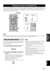
... 9 OFF SUR. Using auto-adjust function The My Beam microphone on the walls in your listening room or when you do not want the sound beams to be reflected on the remote control collects the test tones from this unit so that the beam angle can collect the test tones...music or movies at night. TV/AV YSP 2 Press and hold MY BEAM for more than two seconds. A test tone is output twice from the subwoofer connected to My Beam, which outputs sound beams directly toward this unit. PLAYING BACK SOUND CLEARLY (MY BEAM) Playing back sound clearly (My Beam) You can improve listenability...
... 9 OFF SUR. Using auto-adjust function The My Beam microphone on the walls in your listening room or when you do not want the sound beams to be reflected on the remote control collects the test tones from this unit so that the beam angle can collect the test tones...music or movies at night. TV/AV YSP 2 Press and hold MY BEAM for more than two seconds. A test tone is output twice from the subwoofer connected to My Beam, which outputs sound beams directly toward this unit. PLAYING BACK SOUND CLEARLY (MY BEAM) Playing back sound clearly (My Beam) You can improve listenability...
Owner's Manual
Page 76
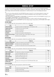
... in the speaker settings menu. • Make settings for the parameters in BEAM MENU first before making settings for sound signals, sound beams, digital input, and the OSD. Adjusts the various subwoofer settings. Page 78 78 78 79 79 79 79 BEAM MENU Use to manually adjust the various parameters related to... the display. Adjusts the sound position of the source. Page 80 80 80 81 81 82 DISPLAY MENU Use to ...
... in the speaker settings menu. • Make settings for the parameters in BEAM MENU first before making settings for sound signals, sound beams, digital input, and the OSD. Adjusts the various subwoofer settings. Page 78 78 78 79 79 79 79 BEAM MENU Use to manually adjust the various parameters related to... the display. Adjusts the sound position of the source. Page 80 80 80 81 81 82 DISPLAY MENU Use to ...


