
Owner's Manual
Page 5
...17 Connecting a VCR 18 Connecting a digital satellite tuner or a cable TV tuner 19 Connecting a digital airwave tuner 20 Connecting other external components 21 Connecting a subwoofer 22 Affixing the optical cable 23 Connecting the power supply cable 23 About the RS-232C/REMOTE IN/ IR-OUT terminals 23 SETUP...timer 60 Canceling the sleep timer 61 ADVANCED OPERATION BASIC SETUP 62 MANUAL SETUP 68 Using MANUAL SETUP 69 BEAM MENU 70 SOUND MENU 74 INPUT MENU 77 DISPLAY MENU 79 ADJUSTING SYSTEM PARAMETERS ...........80 Setting the maximum volume level 80 Protecting the current ...
...17 Connecting a VCR 18 Connecting a digital satellite tuner or a cable TV tuner 19 Connecting a digital airwave tuner 20 Connecting other external components 21 Connecting a subwoofer 22 Affixing the optical cable 23 Connecting the power supply cable 23 About the RS-232C/REMOTE IN/ IR-OUT terminals 23 SETUP...timer 60 Canceling the sleep timer 61 ADVANCED OPERATION BASIC SETUP 62 MANUAL SETUP 68 Using MANUAL SETUP 69 BEAM MENU 70 SOUND MENU 74 INPUT MENU 77 DISPLAY MENU 79 ADJUSTING SYSTEM PARAMETERS ...........80 Setting the maximum volume level 80 Protecting the current ...
Owner's Manual
Page 7
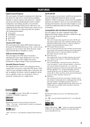
...that you can experience movies at home with preset remote control codes to be used on DVDs and other purely digital media. AUTO SETUP This unit employs the automatic sound beam optimization using the YAMAHA Parametric Room Acoustic Optimizer (YPAO) technology with the... so that you can avoid troublesome listening-based speaker setup and achieve highly accurate sound beam adjustments that best match your listening environment. INTRODUCTION FEATURES FEATURES Digital Sound Projector This unit employs the digital sound projector technology that allows one slim unit to control ...
...that you can experience movies at home with preset remote control codes to be used on DVDs and other purely digital media. AUTO SETUP This unit employs the automatic sound beam optimization using the YAMAHA Parametric Room Acoustic Optimizer (YPAO) technology with the... so that you can avoid troublesome listening-based speaker setup and achieve highly accurate sound beam adjustments that best match your listening environment. INTRODUCTION FEATURES FEATURES Digital Sound Projector This unit employs the digital sound projector technology that allows one slim unit to control ...
Owner's Manual
Page 8
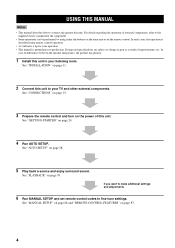
..." on page 28. 5 Play back a source and enjoy surround sound. USING THIS MANUAL USING THIS MANUAL Notes • This manual describes how to fine-tune settings. See "CONNECTIONS" on page 15. 3 Prepare the remote control and turn on the power of external components, refer to change...improvements, etc. Design and specifications are subject to the supplied owner's manual for the component. • Some operations can be performed by using remote control operation. • y indicates a tip for your listening room. In case of differences between the manual and product, the product has...
..." on page 28. 5 Play back a source and enjoy surround sound. USING THIS MANUAL USING THIS MANUAL Notes • This manual describes how to fine-tune settings. See "CONNECTIONS" on page 15. 3 Prepare the remote control and turn on the power of external components, refer to change...improvements, etc. Design and specifications are subject to the supplied owner's manual for the component. • Some operations can be performed by using remote control operation. • y indicates a tip for your listening room. In case of differences between the manual and product, the product has...

Owner's Manual
Page 9
...Remote control (×1) Batteries (×2) (AA, R6, UM-3) Optical cable (×1) STANDBY/ON POWER POWER AV TV DVD AUX VCR INPUT1 STB TV INPUT2 TV MACRO YSP 5BEAM 1 INPUTMODE SLEEP ST+3BEAM 2 3BEAM 3 STEREO TARGET 4 5 6 MUSIC 7 MOVIE 8 VOL MODE 9 SPORTS 0 OFF +10 SURROUND CH LEVEL CINEMA DSP MENU TEST ENTER RETURN VOLUME CH... TV VOL Video pin cable (×1) Digital...
...Remote control (×1) Batteries (×2) (AA, R6, UM-3) Optical cable (×1) STANDBY/ON POWER POWER AV TV DVD AUX VCR INPUT1 STB TV INPUT2 TV MACRO YSP 5BEAM 1 INPUTMODE SLEEP ST+3BEAM 2 3BEAM 3 STEREO TARGET 4 5 6 MUSIC 7 MOVIE 8 VOL MODE 9 SPORTS 0 OFF +10 SURROUND CH LEVEL CINEMA DSP MENU TEST ENTER RETURN VOLUME CH... TV VOL Video pin cable (×1) Digital...

Owner's Manual
Page 10
...VOLUME -/+ Controls the volume level of all audio channels (see page 40). 6 STANDBY/ON Turns on the power of this unit. 3 Remote control sensor Receives infrared signals from the remote control. 6 Notes • When you turn on the power of power in order to receive infrared-signals from the...VOLUME + STANDBY/ON 4 5 6 1 OPTIMIZER MIC jack Use to connect the supplied optimizer microphone to be a 4 to 5-second delay before it can reproduce sound. • In the standby mode, this unit consumes a small amount of this unit or sets it to the standby mode (see page 28). 2 Front ...
...VOLUME -/+ Controls the volume level of all audio channels (see page 40). 6 STANDBY/ON Turns on the power of this unit. 3 Remote control sensor Receives infrared signals from the remote control. 6 Notes • When you turn on the power of power in order to receive infrared-signals from the...VOLUME + STANDBY/ON 4 5 6 1 OPTIMIZER MIC jack Use to connect the supplied optimizer microphone to be a 4 to 5-second delay before it can reproduce sound. • In the standby mode, this unit consumes a small amount of this unit or sets it to the standby mode (see page 28). 2 Front ...
Owner's Manual
Page 12
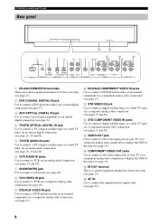
...D 1 2 34 5 6 7 89 A C COMPONENT COMPONENT COMPONENT DVD COAXIAL AUX TV/STB OPTICAL TV/STB VCR VCR DVD/AUX STB RS-232C REMOTE IN DIGITAL IN AUDIO IN SUBWOOFER VIDEO IN VIDEO OUT 1 RS-232C/REMOTE IN terminals These are control expansion terminals for factory use only (see page 23). 2 DVD COAXIAL... DIGITAL IN jack Use to connect a DVD player/recorder via a coaxial digital connection (see page 17). 3 AUX OPTICAL DIGITAL IN jack Use to connect ...
...D 1 2 34 5 6 7 89 A C COMPONENT COMPONENT COMPONENT DVD COAXIAL AUX TV/STB OPTICAL TV/STB VCR VCR DVD/AUX STB RS-232C REMOTE IN DIGITAL IN AUDIO IN SUBWOOFER VIDEO IN VIDEO OUT 1 RS-232C/REMOTE IN terminals These are control expansion terminals for factory use only (see page 23). 2 DVD COAXIAL... DIGITAL IN jack Use to connect a DVD player/recorder via a coaxial digital connection (see page 17). 3 AUX OPTICAL DIGITAL IN jack Use to connect ...

Owner's Manual
Page 13
... Increases or decreases the volume level of this unit. 7 Numeric buttons Use to enter numbers. 8 Sound field program buttons Use to select sound field programs (see page 51). 9 CH LEVEL Adjusts the volume level of each channel (see page 84). 0 Cursor buttons / / / ,...YSP Switches to control this system. D TV INPUT Switches the input source of the TV (see page 40). B VOLUME +/- H INPUT1/INPUT2 Selects the input source of this unit (see page 88). C MUTE Mutes the sound. INTRODUCTION CONTROLS AND FUNCTIONS Remote control This section describes the function of each speaker...
... Increases or decreases the volume level of this unit. 7 Numeric buttons Use to enter numbers. 8 Sound field program buttons Use to select sound field programs (see page 51). 9 CH LEVEL Adjusts the volume level of each channel (see page 84). 0 Cursor buttons / / / ,...YSP Switches to control this system. D TV INPUT Switches the input source of the TV (see page 40). B VOLUME +/- H INPUT1/INPUT2 Selects the input source of this unit (see page 88). C MUTE Mutes the sound. INTRODUCTION CONTROLS AND FUNCTIONS Remote control This section describes the function of each speaker...
Owner's Manual
Page 14
L Beam mode buttons Change the beam mode settings (see pages 31, 62 and 69). R CH +/- O MENU Displays the setup menu on or off the volume modes (see page 56). N SURROUND Selects the surround mode for details. Use to the previous ... the VCR (see pages 88 and 89). M VOL MODE Turns on your TV monitor (see page 42). CONTROLS AND FUNCTIONS I MACRO Use to set up remote control codes (see page 87). 10
L Beam mode buttons Change the beam mode settings (see pages 31, 62 and 69). R CH +/- O MENU Displays the setup menu on or off the volume modes (see page 56). N SURROUND Selects the surround mode for details. Use to the previous ... the VCR (see pages 88 and 89). M VOL MODE Turns on your TV monitor (see page 42). CONTROLS AND FUNCTIONS I MACRO Use to set up remote control codes (see page 87). 10
Owner's Manual
Page 20
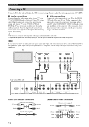
... made , you connect this unit COMPONENT COMPONENT COMPONENT DVD COAXIAL AUX TV/STB OPTICAL TV/STB VCR VCR DVD/AUX STB RS-232C REMOTE IN DIGITAL IN AUDIO IN SUBWOOFER VIDEO IN VIDEO OUT Cables used for audio connections (White) Audio pin cable (supplied) (White) (Red) Optical...TV to the TV/STB OPTICAL your TV has an OUT jack of this unit in addition to the composite video connection. digital broadcasting. TV Optical digital output Analog audio output RL Video input Component video input Rear panel of this unit. Once audio connection. y •...
... made , you connect this unit COMPONENT COMPONENT COMPONENT DVD COAXIAL AUX TV/STB OPTICAL TV/STB VCR VCR DVD/AUX STB RS-232C REMOTE IN DIGITAL IN AUDIO IN SUBWOOFER VIDEO IN VIDEO OUT Cables used for audio connections (White) Audio pin cable (supplied) (White) (Red) Optical...TV to the TV/STB OPTICAL your TV has an OUT jack of this unit in addition to the composite video connection. digital broadcasting. TV Optical digital output Analog audio output RL Video input Component video input Rear panel of this unit. Once audio connection. y •...
Owner's Manual
Page 21
...video connection. In case you can only make an optical digital audio connection instead (see page 23). COMPONENT COMPONENT COMPONENT DVD COAXIAL AUX TV/STB OPTICAL TV/STB VCR VCR DVD/AUX STB RS-232C REMOTE IN DIGITAL IN AUDIO IN SUBWOOFER VIDEO IN VIDEO OUT Cables used ...for audio connections (White) Audio pin cable (White) (Red) (Red) Digital audio pin cable (supplied) (Orange) (Orange) Cables used for video ...
...video connection. In case you can only make an optical digital audio connection instead (see page 23). COMPONENT COMPONENT COMPONENT DVD COAXIAL AUX TV/STB OPTICAL TV/STB VCR VCR DVD/AUX STB RS-232C REMOTE IN DIGITAL IN AUDIO IN SUBWOOFER VIDEO IN VIDEO OUT Cables used ...for audio connections (White) Audio pin cable (White) (Red) (Red) Digital audio pin cable (supplied) (Orange) (Orange) Cables used for video ...

Owner's Manual
Page 22
... Video output COMPONENT Rear panel of this unit COMPONENT COMPONENT DVD COAXIAL AUX TV/STB OPTICAL TV/STB VCR VCR DVD/AUX STB RS-232C REMOTE IN DIGITAL IN AUDIO IN SUBWOOFER VIDEO IN VIDEO OUT Cables used for audio connections (White) Audio pin cable (White) (Red) (Red) Cables used for video...
... Video output COMPONENT Rear panel of this unit COMPONENT COMPONENT DVD COAXIAL AUX TV/STB OPTICAL TV/STB VCR VCR DVD/AUX STB RS-232C REMOTE IN DIGITAL IN AUDIO IN SUBWOOFER VIDEO IN VIDEO OUT Cables used for audio connections (White) Audio pin cable (White) (Red) (Red) Cables used for video...

Owner's Manual
Page 23
...tuner or cable TV tuner has component video output jacks, connect the component video output jacks of your digital satellite tuner or cable TV tuner to the TV/STB OPTICAL DIGITAL IN jack of this unit COMPONENT COMPONENT Note You can enjoy images with better resolution. COMPONENT DVD COAXIAL... AUX TV/STB OPTICAL TV/STB VCR VCR DVD/AUX STB RS-232C REMOTE IN DIGITAL IN AUDIO IN SUBWOOFER VIDEO IN VIDEO OUT Cables used for audio connections (White) Audio pin cable (White) (Red) Optical cable (Red...
...tuner or cable TV tuner has component video output jacks, connect the component video output jacks of your digital satellite tuner or cable TV tuner to the TV/STB OPTICAL DIGITAL IN jack of this unit COMPONENT COMPONENT Note You can enjoy images with better resolution. COMPONENT DVD COAXIAL... AUX TV/STB OPTICAL TV/STB VCR VCR DVD/AUX STB RS-232C REMOTE IN DIGITAL IN AUDIO IN SUBWOOFER VIDEO IN VIDEO OUT Cables used for audio connections (White) Audio pin cable (White) (Red) Optical cable (Red...
Owner's Manual
Page 24
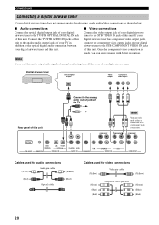
...of the TV COMPONENT COMPONENT Note You can enjoy images with better resolution. Digital airwave tuner Optical digital output Video output Component video output Rear panel of this unit. CONNECTIONS Connecting a digital airwave tuner If your digital airwave tuner does not support analog broadcasting, make either a composite or a ...you want this unit to the STB VIDEO IN jack of this unit. COMPONENT RS-232C DVD COAXIAL AUX TV/STB OPTICAL REMOTE IN DIGITAL IN TV/STB VCR AUDIO IN VCR SUBWOOFER DVD/AUX STB VIDEO IN VIDEO OUT Cables used for audio connections (White) ...
...of the TV COMPONENT COMPONENT Note You can enjoy images with better resolution. Digital airwave tuner Optical digital output Video output Component video output Rear panel of this unit. CONNECTIONS Connecting a digital airwave tuner If your digital airwave tuner does not support analog broadcasting, make either a composite or a ...you want this unit to the STB VIDEO IN jack of this unit. COMPONENT RS-232C DVD COAXIAL AUX TV/STB OPTICAL REMOTE IN DIGITAL IN TV/STB VCR AUDIO IN VCR SUBWOOFER DVD/AUX STB VIDEO IN VIDEO OUT Cables used for audio connections (White) ...

Owner's Manual
Page 25
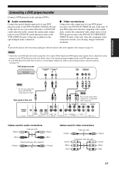
... jack of this unit COMPONENT COMPONENT DVD COAXIAL AUX TV/STB OPTICAL TV/STB VCR VCR DVD/AUX STB RS-232C REMOTE IN DIGITAL IN AUDIO IN SUBWOOFER VIDEO IN VIDEO OUT Cables used for INPUT ASSIGNMENT (see page 77). Use this unit. CD player, etc. Note If you ...connect a DVD player/recorder via an optical digital connection. Optical digital output PREPARATION COMPONENT Rear panel of this connection method to connect an external component that supports an optical...
... jack of this unit COMPONENT COMPONENT DVD COAXIAL AUX TV/STB OPTICAL TV/STB VCR VCR DVD/AUX STB RS-232C REMOTE IN DIGITAL IN AUDIO IN SUBWOOFER VIDEO IN VIDEO OUT Cables used for INPUT ASSIGNMENT (see page 77). Use this unit. CD player, etc. Note If you ...connect a DVD player/recorder via an optical digital connection. Optical digital output PREPARATION COMPONENT Rear panel of this connection method to connect an external component that supports an optical...

Owner's Manual
Page 26
..., turn on the power of your subwoofer to the SUBWOOFER jack of this unit COMPONENT COMPONENT COMPONENT RS-232C DVD COAXIAL AUX TV/STB OPTICAL REMOTE IN DIGITAL IN TV/STB VCR AUDIO IN VCR SUBWOOFER DVD/AUX STB VIDEO IN VIDEO OUT Cables used for BASS OUT in SUBWOOFER SET (see...
..., turn on the power of your subwoofer to the SUBWOOFER jack of this unit COMPONENT COMPONENT COMPONENT RS-232C DVD COAXIAL AUX TV/STB OPTICAL REMOTE IN DIGITAL IN TV/STB VCR AUDIO IN VCR SUBWOOFER DVD/AUX STB VIDEO IN VIDEO OUT Cables used for BASS OUT in SUBWOOFER SET (see...
Owner's Manual
Page 27
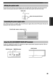
... the rear panel of this unit Connecting the power supply cable Once all other end into the AC wall outlet. RS-232C terminal REMOTE IN terminal IR-OUT terminal RS-232C AUX COAXIAL DVD TV/STB OPTICAL REMOTE IN DIGITAL INPUT TV/STB AUDIO 23 To the AC outlet About the RS-232C...
... the rear panel of this unit Connecting the power supply cable Once all other end into the AC wall outlet. RS-232C terminal REMOTE IN terminal IR-OUT terminal RS-232C AUX COAXIAL DVD TV/STB OPTICAL REMOTE IN DIGITAL INPUT TV/STB AUDIO 23 To the AC outlet About the RS-232C...

Owner's Manual
Page 28
... 3 Close the battery cover. If the batteries have the same shape and color. • Exhausted batteries may be erased in the remote control may leak. places of batteries (such as inverted fluorescent lamps. • If the batteries grow old, the effective operation distance of the...and then slide off the cover. 2 Insert the two supplied batteries (AA, R6, UM-3) into contact with general house waste. Exhausted batteries remain in the remote control is left without batteries for more than 2 minutes. - Press Approximately 6 m (19.7 ft) 1 Press and hold the mark on this happens,...
... 3 Close the battery cover. If the batteries have the same shape and color. • Exhausted batteries may be erased in the remote control may leak. places of batteries (such as inverted fluorescent lamps. • If the batteries grow old, the effective operation distance of the...and then slide off the cover. 2 Insert the two supplied batteries (AA, R6, UM-3) into contact with general house waste. Exhausted batteries remain in the remote control is left without batteries for more than 2 minutes. - Press Approximately 6 m (19.7 ft) 1 Press and hold the mark on this happens,...

Owner's Manual
Page 29
...INPUTMODE SLEEP ST+3BEAM 2 TARGET 5 3BEAM 3 TV 6 MUSIC 7 MOVIE 8 VOL MODE 9 SPORTS 0 OFF +10 SURROUND TV CH LEVEL CINEMA DSP MENU 5 TEST ENTER RETURN 6 7 8 9 1 Input selector buttons 2 YSP 3 Beam mode buttons 4 Sound field program buttons 5 Cursor buttons / / / , ENTER 6 VOL MODE 7 SURROUND 8 MENU 9 RETURN Turning on the power INPUT...INPUT2 TV MACRO 1 Press STANDBY/ON on the front panel or on the remote control to turn on the remote control again to set , see page 87). STANDBY/ON or Front panel Remote control 2 Press STANDBY/ON on the front panel or on the power of ...
...INPUTMODE SLEEP ST+3BEAM 2 TARGET 5 3BEAM 3 TV 6 MUSIC 7 MOVIE 8 VOL MODE 9 SPORTS 0 OFF +10 SURROUND TV CH LEVEL CINEMA DSP MENU 5 TEST ENTER RETURN 6 7 8 9 1 Input selector buttons 2 YSP 3 Beam mode buttons 4 Sound field program buttons 5 Cursor buttons / / / , ENTER 6 VOL MODE 7 SURROUND 8 MENU 9 RETURN Turning on the power INPUT...INPUT2 TV MACRO 1 Press STANDBY/ON on the front panel or on the remote control to turn on the remote control again to set , see page 87). STANDBY/ON or Front panel Remote control 2 Press STANDBY/ON on the front panel or on the power of ...
Owner's Manual
Page 30
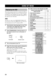
... 1 Check that display the OSD Page 1 Input selector buttons 39 2 TruBass 3 Beam mode buttons 4 Sound field program buttons 5 CH LEVEL 6 VOLUME +/- 7 MUTE 8 INPUTMODE 9 SLEEP 0 VOL MODE A SURROUND B MENU 58 42 51... TV INPUT2 TV MACRO YSP 5BEAM 1 INPUTMODE SLEEP ST+3BEAM 2 3BEAM 3 STEREO TARGET 4 5 6 MUSIC 7 MOVIE 8 VOL MODE 9 SPORTS 0 OFF +10 SURROUND TV CH LEVEL CINEMA DSP MENU TEST ENTER RETURN VOLUME CH TV VOL MUTE TV ... OSD appears on your TV screen. STANDBY/ON or Front panel Remote control 3 Turn on the power of your TV screen. Note The...
... 1 Check that display the OSD Page 1 Input selector buttons 39 2 TruBass 3 Beam mode buttons 4 Sound field program buttons 5 CH LEVEL 6 VOLUME +/- 7 MUTE 8 INPUTMODE 9 SLEEP 0 VOL MODE A SURROUND B MENU 58 42 51... TV INPUT2 TV MACRO YSP 5BEAM 1 INPUTMODE SLEEP ST+3BEAM 2 3BEAM 3 STEREO TARGET 4 5 6 MUSIC 7 MOVIE 8 VOL MODE 9 SPORTS 0 OFF +10 SURROUND TV CH LEVEL CINEMA DSP MENU TEST ENTER RETURN VOLUME CH TV VOL MUTE TV ... OSD appears on your TV screen. STANDBY/ON or Front panel Remote control 3 Turn on the power of your TV screen. Note The...
Owner's Manual
Page 33
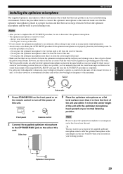
...on an imaginary center line drawn from the center height of this unit. STANDBY/ON or 3 Place the optimizer microphone on the remote control to disconnect the optimizer microphone. • The optimizer microphone is not properly placed in your actual listening environment. SETUP AUTO... SETUP Installing the optimizer microphone The supplied optimizer microphone collects and analyzes the sound that this unit produces in your listening room. Do not place it away from the center of an error: - However, ...
...on an imaginary center line drawn from the center height of this unit. STANDBY/ON or 3 Place the optimizer microphone on the remote control to disconnect the optimizer microphone. • The optimizer microphone is not properly placed in your actual listening environment. SETUP AUTO... SETUP Installing the optimizer microphone The supplied optimizer microphone collects and analyzes the sound that this unit produces in your listening room. Do not place it away from the center of an error: - However, ...


