
MCXSP10 Manual
Page 1
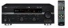
U RX-V559 AV Receiver OWNER'S MANUAL
U RX-V559 AV Receiver OWNER'S MANUAL
MCXSP10 Manual
Page 7
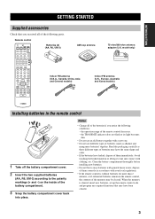
...the memory may have the same shape and color. • If the batteries have been cleared. 3 Notes • Change all of the batteries if you received all of the following conditions: - the operation range of them correctly in accordance with a new one. • Do not use an old battery together ...Do not use different types of batteries (such as these different types of batteries may be cleared. Remote control CODE SET TRANSMIT POWER TV POWER AV STANDBY POWER CD DVD MD CD-R CBL DTV SLEEP XM TUNER MULTI CH IN V-AUX DVR TV VOL TV CH AMP VOLUME SOURCE TV TV...
...the memory may have the same shape and color. • If the batteries have been cleared. 3 Notes • Change all of the batteries if you received all of the following conditions: - the operation range of them correctly in accordance with a new one. • Do not use an old battery together ...Do not use different types of batteries (such as these different types of batteries may be cleared. Remote control CODE SET TRANSMIT POWER TV POWER AV STANDBY POWER CD DVD MD CD-R CBL DTV SLEEP XM TUNER MULTI CH IN V-AUX DVR TV VOL TV CH AMP VOLUME SOURCE TV TV...
MCXSP10 Manual
Page 8
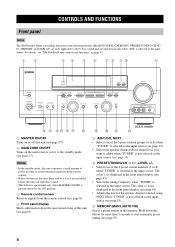
..."XM" is selected as the input source. Notes • In the standby mode, this unit consumes a small amount of power in order to receive infrared signals from the remote control (see page 8). 4 Front panel display Shows information about the operational status of the speaker channel selected using NEXT when...). • Selects the speaker channel whose output level you turn on the main zone or sets it to the ON position. 3 Remote control sensor Receives signals from the remote control. • When you want to adjust when "TUNER" is not selected as the input source (see page 45). •...
..."XM" is selected as the input source. Notes • In the standby mode, this unit consumes a small amount of power in order to receive infrared signals from the remote control (see page 8). 4 Front panel display Shows information about the operational status of the speaker channel selected using NEXT when...). • Selects the speaker channel whose output level you turn on the main zone or sets it to the ON position. 3 Remote control sensor Receives signals from the remote control. • When you want to adjust when "TUNER" is not selected as the input source (see page 45). •...
MCXSP10 Manual
Page 13
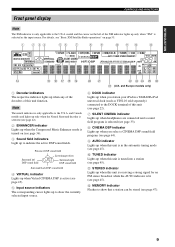
...to show the currently selected input source. Presence DSP sound field Surround left of the XM indicator lights up when this unit is receiving a strong signal for an FM stereo broadcast while the AUTO indicator is only applicable to the U.S.A. INTRODUCTION Front panel display CONTROLS AND FUNCTIONS ... indicator Lights up when you select a CINEMA DSP sound field program (see page 64). 9 AUTO indicator Lights up when this unit is in a YAMAHA iPod universal dock (such as the input source. For details, see "Basic XM Satellite Radio operations" on (see page 47). 9 JK L MN O P Q ...
...to show the currently selected input source. Presence DSP sound field Surround left of the XM indicator lights up when this unit is receiving a strong signal for an FM stereo broadcast while the AUTO indicator is only applicable to the U.S.A. INTRODUCTION Front panel display CONTROLS AND FUNCTIONS ... indicator Lights up when you select a CINEMA DSP sound field program (see page 64). 9 AUTO indicator Lights up when this unit is in a YAMAHA iPod universal dock (such as the input source. For details, see "Basic XM Satellite Radio operations" on (see page 47). 9 JK L MN O P Q ...
MCXSP10 Manual
Page 14
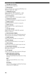
E STANDARD indicator Lights up when the Radio Data System data is being received. O Input channel indicators Indicate the channel components of the current sound field program and other information when adjusting or changing settings. and Europe models only) ... searching for the Radio Data System stations in the PTY SEEK mode. 10 STANDARD" or "SUR. N 96/24 indicator Lights up when Zone 2 is being received. D PCM indicator Lights up when you select a night listening mode (see page 42). G Headphones indicator Lights up while the sleep timer is selected (see page...
E STANDARD indicator Lights up when the Radio Data System data is being received. O Input channel indicators Indicate the channel components of the current sound field program and other information when adjusting or changing settings. and Europe models only) ... searching for the Radio Data System stations in the PTY SEEK mode. 10 STANDARD" or "SUR. N 96/24 indicator Lights up when Zone 2 is being received. D PCM indicator Lights up when you select a night listening mode (see page 42). G Headphones indicator Lights up while the sleep timer is selected (see page...
MCXSP10 Manual
Page 23
...). model) COMPONENT VIDEO DVD Y PB PR 19 When recording a source, you connected your TV to the VIDEO jacks. • When "VIDEO CONV." The cable TV receiver and the satellite receiver are complete. is set -top box) using the same type of the STB.
...). model) COMPONENT VIDEO DVD Y PB PR 19 When recording a source, you connected your TV to the VIDEO jacks. • When "VIDEO CONV." The cable TV receiver and the satellite receiver are complete. is set -top box) using the same type of the STB.

MCXSP10 Manual
Page 24
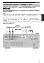
CONNECTIONS ■ Connecting a DVD recorder or a VCR AUDIO IN DVR OUT VIDEO IN DVR OUT S VIDEO (U.S.A. model) COMPONENT VIDEO Y PB PR DTV/CBL 20 model) COMPONENT VIDEO DVR Y PB PR Audio out Audio in Video out Video in S-video out S-video in RL RL V V S S Y PB PR ■ Connecting an STB DVD recorder or VCR Cable TV receiver or satellite receiver Component video out Component video out Audio out Video out S-video out Optical audio out RL V S AUDIO DTV/CBL VIDEO DTV/CBL S VIDEO O DIGITAL INPUT DTV/CBL OPTICAL Y PB PR (U.S.A.
CONNECTIONS ■ Connecting a DVD recorder or a VCR AUDIO IN DVR OUT VIDEO IN DVR OUT S VIDEO (U.S.A. model) COMPONENT VIDEO Y PB PR DTV/CBL 20 model) COMPONENT VIDEO DVR Y PB PR Audio out Audio in Video out Video in S-video out S-video in RL RL V V S S Y PB PR ■ Connecting an STB DVD recorder or VCR Cable TV receiver or satellite receiver Component video out Component video out Audio out Video out S-video out Optical audio out RL V S AUDIO DTV/CBL VIDEO DTV/CBL S VIDEO O DIGITAL INPUT DTV/CBL OPTICAL Y PB PR (U.S.A.
MCXSP10 Manual
Page 49
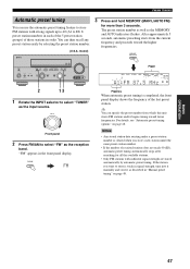
... INPUT selector to turn the colon (:) off. You can recall any preset stations and exchange the assignment of two preset stations with each of the received station is weak, tune into a lower frequency. If the signal from the station you can also use the automatic and manual preset tuning features to...
... INPUT selector to turn the colon (:) off. You can recall any preset stations and exchange the assignment of two preset stations with each of the received station is weak, tune into a lower frequency. If the signal from the station you can also use the automatic and manual preset tuning features to...
MCXSP10 Manual
Page 50
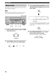
... colon (:) If a colon (:) appears in the front panel display. Note Manually tuning into the desired station manually. FM/AM TUNING Manual tuning If the signal received from the front panel display. Press PRESET/TUNING to select the reception band.
... colon (:) If a colon (:) appears in the front panel display. Note Manually tuning into the desired station manually. FM/AM TUNING Manual tuning If the signal received from the front panel display. Press PRESET/TUNING to select the reception band.
MCXSP10 Manual
Page 51
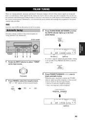
... feature to store FM stations with strong signals up to 40 (A1 to E8: 8 preset station numbers in each of the 5 preset station groups) of received stations does not reach 40 (E8), automatic preset tuning automatically stops after searching for more than 3 seconds. "FM" appears in "Manual preset tuning" on page...
... feature to store FM stations with strong signals up to 40 (A1 to E8: 8 preset station numbers in each of the 5 preset station groups) of received stations does not reach 40 (E8), automatic preset tuning automatically stops after searching for more than 3 seconds. "FM" appears in "Manual preset tuning" on page...
MCXSP10 Manual
Page 52
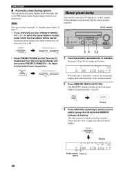
... first station will be stored. Note First carry out steps 1 through 3 in the front panel display. The MEMORY indicator flashes in each of the station received. 2 Press MEMORY (MAN'L/AUTO FM). Automatic preset tuning stops when stations have all been stored up to 40 stations (A1 to select the preset station...
... first station will be stored. Note First carry out steps 1 through 3 in the front panel display. The MEMORY indicator flashes in each of the station received. 2 Press MEMORY (MAN'L/AUTO FM). Automatic preset tuning stops when stations have all been stored up to 40 stations (A1 to select the preset station...

MCXSP10 Manual
Page 56
and more than 20 channels of the traffic and weather information for XM radio receivers by calling "1-800-XM-RADIO (1-800-967-2346)". To check your ID number, follow "Activating XM Satellite Radio" on XM Satellite Radio services, visit the ...
and more than 20 channels of the traffic and weather information for XM radio receivers by calling "1-800-XM-RADIO (1-800-967-2346)". To check your ID number, follow "Activating XM Satellite Radio" on XM Satellite Radio services, visit the ...
MCXSP10 Manual
Page 97
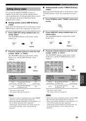
...to select "TUNER" as the input source. Setting library codes You can operate multiple YAMAHA receivers or amplifiers in the advanced setup (see page 89). • When using multiple YAMAHA receivers/amplifiers, you may be able to operate the other components simultaneously with the default code...ID *2 ID1 (initial setting) ID2 *1 The remote control setting *2 The setting of this unit (see page 89). • When using multiple YAMAHA receivers/amplifiers, you want to use . 1 Press CODE SET using a ballpoint pen or a similar object. The TRANSMIT indicator on the remote control flashes...
...to select "TUNER" as the input source. Setting library codes You can operate multiple YAMAHA receivers or amplifiers in the advanced setup (see page 89). • When using multiple YAMAHA receivers/amplifiers, you may be able to operate the other components simultaneously with the default code...ID *2 ID1 (initial setting) ID2 *1 The remote control setting *2 The setting of this unit (see page 89). • When using multiple YAMAHA receivers/amplifiers, you want to use . 1 Press CODE SET using a ballpoint pen or a similar object. The TRANSMIT indicator on the remote control flashes...
MCXSP10 Manual
Page 98
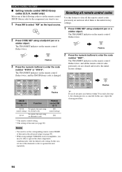
...; You need to set the corresponding remote control XM ID of this case, set one of this unit (see page 89). • When using multiple YAMAHA receivers/amplifiers, you may be able to enter the code number "9981". STEREO 1 MUSIC ENTERTAIN MOVIE 2 3 4 STANDARD SELECT EXTD SUR. In this unit using (initial setting...
...; You need to set the corresponding remote control XM ID of this case, set one of this unit (see page 89). • When using multiple YAMAHA receivers/amplifiers, you may be able to enter the code number "9981". STEREO 1 MUSIC ENTERTAIN MOVIE 2 3 4 STANDARD SELECT EXTD SUR. In this unit using (initial setting...
MCXSP10 Manual
Page 99
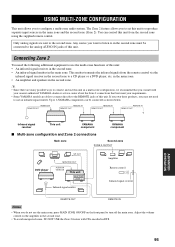
.... This emitter transmits the infrared signals from the second zone using the supplied remote control. Up to 6 YAMAHA components can control this unit: • An infrared signal receiver in the second zone. • An infrared signal emitter in the main zone. You can be connected ...multi-zone audio system. REMOTE IN REMOTE OUT REMOTE IN REMOTE OUT REMOTE IN REMOTE OUT REMOTE IN REMOTE OUT Infrared signal receiver This unit YAMAHA component YAMAHA component ■ Multi-zone configuration and Zone 2 connections Main zone Second zone ZONE 2 OUTPUT SP OUT DVD player MONITOR OUT...
.... This emitter transmits the infrared signals from the second zone using the supplied remote control. Up to 6 YAMAHA components can control this unit: • An infrared signal receiver in the second zone. • An infrared signal emitter in the main zone. You can be connected ...multi-zone audio system. REMOTE IN REMOTE OUT REMOTE IN REMOTE OUT REMOTE IN REMOTE OUT REMOTE IN REMOTE OUT Infrared signal receiver This unit YAMAHA component YAMAHA component ■ Multi-zone configuration and Zone 2 connections Main zone Second zone ZONE 2 OUTPUT SP OUT DVD player MONITOR OUT...

MCXSP10 Manual
Page 114
LIST OF REMOTE CONTROL CODES CABLE TV RECEIVER ABC 10003, 10008, 10014, 10017, 10033 AMERICAST 10899 BELL & HOWELL 10014 BELL SOUTH 10899 CLEARMASTER 10883 CLEARMAX 10883 COOLMAX 10883 DIGEO 11187 DIGI 10637 ... SYSTEMS 11142, 11442, 11443, 11444 JVC 11170 MOTOROLA 10869 PHILIPS 11142, 11442 PROSCAN 10392 RCA 11392 SAMSUNG 11442 SONY 10639, 11640 STAR CHOICE 10869 SATELLITE RECEIVER ALPHASTAR 10772 CHAPARRAL 10053, 10216 CROSSDIGITAL 11109 DIRECTV 10099, 10247, 10392, 10566, 10639, 10724, 10749, 10819, 11076, 11108, 11109, 11142, 11377, 11392, 11414, 11442, ...
LIST OF REMOTE CONTROL CODES CABLE TV RECEIVER ABC 10003, 10008, 10014, 10017, 10033 AMERICAST 10899 BELL & HOWELL 10014 BELL SOUTH 10899 CLEARMASTER 10883 CLEARMAX 10883 COOLMAX 10883 DIGEO 11187 DIGI 10637 ... SYSTEMS 11142, 11442, 11443, 11444 JVC 11170 MOTOROLA 10869 PHILIPS 11142, 11442 PROSCAN 10392 RCA 11392 SAMSUNG 11442 SONY 10639, 11640 STAR CHOICE 10869 SATELLITE RECEIVER ALPHASTAR 10772 CHAPARRAL 10053, 10216 CROSSDIGITAL 11109 DIRECTV 10099, 10247, 10392, 10566, 10639, 10724, 10749, 10819, 11076, 11108, 11109, 11142, 11377, 11392, 11414, 11442, ...


