
MCXSP10 Manual
Page 2
... instructions should be operated only from the wall outlet before the product is operated. 2 Retain Instructions - Unplug this product from the type of power source indicated on the product. 18 Servicing - for example, near a swimming pool; or near a bath tub, wash bowl, kitchen sink,...read before cleaning. Quick stops, excessive force, and uneven surfaces may expose you to dangerous voltage or other sources, refer to . 11 Power Sources - Slots and openings in the literature accompanying the appliance. 1 Read Instructions - This product should be blocked by placing the product...
... instructions should be operated only from the wall outlet before the product is operated. 2 Retain Instructions - Unplug this product from the type of power source indicated on the product. 18 Servicing - for example, near a swimming pool; or near a bath tub, wash bowl, kitchen sink,...read before cleaning. Quick stops, excessive force, and uneven surfaces may expose you to dangerous voltage or other sources, refer to . 11 Power Sources - Slots and openings in the literature accompanying the appliance. 1 Read Instructions - This product should be blocked by placing the product...
MCXSP10 Manual
Page 3
... discharge unit, connection to determine that are required, be sure the service technician has used replacement parts specified by Yamaha Corporation of product. Utilize power outlets that the product is in proper operating condition. 22 Wall or Ceiling Mounting - ii Adjust only those products...ELECTRICAL CODE ANTENNA LEAD IN WIRE ANTENNA DISCHARGE UNIT (NEC SECTION 810-20) GROUNDING CONDUCTORS (NEC SECTION 810-21) GROUND CLAMPS POWER SERVICE GROUNDING ELECTRODE SYSTEM (NEC ART 250. If the antenna lead-in is provided to call the CATV system installer's attention to...
... discharge unit, connection to determine that are required, be sure the service technician has used replacement parts specified by Yamaha Corporation of product. Utilize power outlets that the product is in proper operating condition. 22 Wall or Ceiling Mounting - ii Adjust only those products...ELECTRICAL CODE ANTENNA LEAD IN WIRE ANTENNA DISCHARGE UNIT (NEC SECTION 810-20) GROUNDING CONDUCTORS (NEC SECTION 810-21) GROUND CLAMPS POWER SERVICE GROUNDING ELECTRODE SYSTEM (NEC ART 250. If the antenna lead-in is provided to call the CATV system installer's attention to...
MCXSP10 Manual
Page 4
... to use force on the rear of time (i.e. Contact qualified YAMAHA service personnel when any service is faulty. 17 Before moving this unit is called the standby mode. vacation), disconnect the AC power plug from loud sounds is often undetectable until all connections are ...clear without affecting your equipment by lightning, disconnect the power cord and outdoor antenna from the AC power source as long as they may overheat, possibly causing damage. 9 Do not use this unit is needed. YAMAHA and the Electronic Industries Association's Consumer Electronics Group ...
... to use force on the rear of time (i.e. Contact qualified YAMAHA service personnel when any service is faulty. 17 Before moving this unit is called the standby mode. vacation), disconnect the AC power plug from loud sounds is often undetectable until all connections are ...clear without affecting your equipment by lightning, disconnect the power cord and outdoor antenna from the AC power source as long as they may overheat, possibly causing damage. 9 Do not use this unit is needed. YAMAHA and the Electronic Industries Association's Consumer Electronics Group ...
MCXSP10 Manual
Page 5
... connecting components 15 Connecting video components 16 Connecting audio components 19 Connecting the FM and AM antennas 21 Connecting the power supply cord 22 Speaker impedance setting 23 Turning on the power 23 AUTO SETUP 24 Introduction 24 Optimizer microphone setup 24 Starting the setup 25 BASIC OPERATION PLAYBACK 30 Basic operations...
... connecting components 15 Connecting video components 16 Connecting audio components 19 Connecting the FM and AM antennas 21 Connecting the power supply cord 22 Speaker impedance setting 23 Turning on the power 23 AUTO SETUP 24 Introduction 24 Optimizer microphone setup 24 Starting the setup 25 BASIC OPERATION PLAYBACK 30 Basic operations...
MCXSP10 Manual
Page 6
...printed prior to production. In cases when the button names differ between the manual and product, the product has priority. In case of YAMAHA CORPORATION. Design and specifications are trademarks of Digital Theater Systems, Inc. "Dolby", "Pro Logic", "Surround EX", and the double-D ... ◆ Minimum RMS output power (0.06% THD, 20 Hz to 20 kHz, 8 Ω) Front: 95 W + 95 W Center: 95 W Surround: 95 W + 95 W Surround back: 95 W + 95 W Sound field features ◆ Proprietary YAMAHA technology for monitor out ◆ Optical and coaxial digital audio signal jacks ◆ Sleep...
...printed prior to production. In cases when the button names differ between the manual and product, the product has priority. In case of YAMAHA CORPORATION. Design and specifications are trademarks of Digital Theater Systems, Inc. "Dolby", "Pro Logic", "Surround EX", and the double-D ... ◆ Minimum RMS output power (0.06% THD, 20 Hz to 20 kHz, 8 Ω) Front: 95 W + 95 W Center: 95 W Surround: 95 W + 95 W Surround back: 95 W + 95 W Sound field features ◆ Proprietary YAMAHA technology for monitor out ◆ Optical and coaxial digital audio signal jacks ◆ Sleep...

MCXSP10 Manual
Page 7
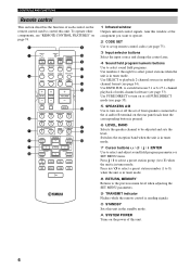
... batteries together with general house waste; LEVEL TITLE BAND PRESET/CH EFFECT SET MENU FAVOR. Remote control CODE SET TRANSMIT POWER TV POWER AV STANDBY CD MD/CD-R TUNER SYSTEM POWER SLEEP DVD DTV/CBL V-AUX MULTI CH IN VCR 1 DVR/VCR2 AMP Batteries (4) (AAA, R03, UM-4) AM...Insert four supplied batteries (AAA, R03, UM-4) according to the polarity markings (+ / -) on batteries • Change all of the batteries if you received all of the following conditions; Notes on the inside of the battery compartment. 3 Slide the cover back until it come into place. 3 If the...
... batteries together with general house waste; LEVEL TITLE BAND PRESET/CH EFFECT SET MENU FAVOR. Remote control CODE SET TRANSMIT POWER TV POWER AV STANDBY CD MD/CD-R TUNER SYSTEM POWER SLEEP DVD DTV/CBL V-AUX MULTI CH IN VCR 1 DVR/VCR2 AMP Batteries (4) (AAA, R03, UM-4) AM...Insert four supplied batteries (AAA, R03, UM-4) according to the polarity markings (+ / -) on batteries • Change all of the batteries if you received all of the following conditions; Notes on the inside of the battery compartment. 3 Slide the cover back until it come into place. 3 If the...
MCXSP10 Manual
Page 8
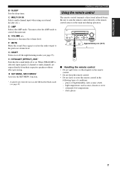
...A/B/C/D/E (NEXT) when the unit is not displayed. Adjusts the level of the 5 preset station groups (A to E) when the unit is in order to receive infrared-signals from the remote control. 2 OPTIMIZER MIC jack Use to connect and input audio signals from the remote control. 4 Front panel display Shows information... about the operational status of this unit can reproduce sound. Note In standby mode, this unit consumes a small amount of power in tuner mode. When you turn on this unit, you will hear a click and there will be adjusted when the unit is not in ...
...A/B/C/D/E (NEXT) when the unit is not displayed. Adjusts the level of the 5 preset station groups (A to E) when the unit is in order to receive infrared-signals from the remote control. 2 OPTIMIZER MIC jack Use to connect and input audio signals from the remote control. 4 Front panel display Shows information... about the operational status of this unit can reproduce sound. Note In standby mode, this unit consumes a small amount of power in tuner mode. When you turn on this unit, you will hear a click and there will be adjusted when the unit is not in ...
MCXSP10 Manual
Page 10
... (A to E) when the unit is in multiple channel format (see page 34). A SYSTEM POWER Turns on the power of multi-channel software (see "REMOTE CONTROL FEATURES" on page 74. 1 2 3 CODE SET TRANSMIT POWER TV POWER AV STANDBY CD MD/CD-R TUNER SYSTEM POWER SLEEP DVD DTV/CBL V-AUX MULTI CH IN VCR 1 DVR/VCR2 AMP TV...
... (A to E) when the unit is in multiple channel format (see page 34). A SYSTEM POWER Turns on the power of multi-channel software (see "REMOTE CONTROL FEATURES" on page 74. 1 2 3 CODE SET TRANSMIT POWER TV POWER AV STANDBY CD MD/CD-R TUNER SYSTEM POWER SLEEP DVD DTV/CBL V-AUX MULTI CH IN VCR 1 DVR/VCR2 AMP TV...
MCXSP10 Manual
Page 11
... INPUT STRAIGHT TONE CONTROL INPUT MODE MULTI CH INPUT PURE DIRECT EFFECT S VIDEO VIDEO AUX VIDEO L AUDIO R OPTICAL 30 30 CODE SET TRANSMIT SYSTEM POWER POWER STANDBY POWER TV AV CD MD/CD-R TUNER SLEEP DVD DTV/CBL V-AUX MULTI CH IN VCR 1 DVR/VCR2 AMP TV VOL TV CH VOLUME TV MUTE TV...
... INPUT STRAIGHT TONE CONTROL INPUT MODE MULTI CH INPUT PURE DIRECT EFFECT S VIDEO VIDEO AUX VIDEO L AUDIO R OPTICAL 30 30 CODE SET TRANSMIT SYSTEM POWER POWER STANDBY POWER TV AV CD MD/CD-R TUNER SLEEP DVD DTV/CBL V-AUX MULTI CH IN VCR 1 DVR/VCR2 AMP TV VOL TV CH VOLUME TV MUTE TV...

MCXSP10 Manual
Page 13
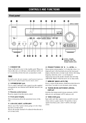
and Europe models only O ZONE 2 indicator Lights up while the sleep timer is on . CONTROLS AND FUNCTIONS 9 INTRODUCTION K SLEEP indicator Lights up when Zone 2 power is on . N Input channel indicators Indicate the channel components of the current digital input signal. ■ U.S.A., Canada, Australia, U.K. M LFE indicator Lights up when a DTS 96/24 signal is input to this unit. L 96/24 indicator Lights up when the input signal contains the LFE signal.
and Europe models only O ZONE 2 indicator Lights up while the sleep timer is on . CONTROLS AND FUNCTIONS 9 INTRODUCTION K SLEEP indicator Lights up when Zone 2 power is on . N Input channel indicators Indicate the channel components of the current digital input signal. ■ U.S.A., Canada, Australia, U.K. M LFE indicator Lights up when a DTS 96/24 signal is input to this unit. L 96/24 indicator Lights up when the input signal contains the LFE signal.

MCXSP10 Manual
Page 14
... information. 4 Antenna terminals See page 21 for details. and Europe models only) This is a control expansion terminal for commercial use. 9 AC OUTLET(S) Use to supply power to your other models) See page 13 for details. See page 78 for connection information. 5 PRESENCE/ZONE 2 speaker terminals (U.S.A., Canada, Australia, U.K. C PRE OUT jacks See...
... information. 4 Antenna terminals See page 21 for details. and Europe models only) This is a control expansion terminal for commercial use. 9 AC OUTLET(S) Use to supply power to your other models) See page 13 for details. See page 78 for connection information. 5 PRESENCE/ZONE 2 speaker terminals (U.S.A., Canada, Australia, U.K. C PRE OUT jacks See...

MCXSP10 Manual
Page 16
..., be sure to set this unit's speaker impedance setting to 4 ohms before using (see page 23). • Before connecting the speakers, make sure that the power of the cable together to the "+" (red) terminals on this unit and/or speakers. • Use magnetically shielded speakers. Open the tab, then insert one...
..., be sure to set this unit's speaker impedance setting to 4 ohms before using (see page 23). • Before connecting the speakers, make sure that the power of the cable together to the "+" (red) terminals on this unit and/or speakers. • Use magnetically shielded speakers. Open the tab, then insert one...
MCXSP10 Manual
Page 19
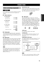
... color reproduction. Do not discard the cap. PREPARATION CONNECTIONS CONNECTIONS Before connecting components CAUTION Do not connect this unit or other components to the mains power until all connections between components are compatible with 96-kHz sampling digital signals. This cap protects the jack from the COAXIAL jack. Likewise, signals input...
... color reproduction. Do not discard the cap. PREPARATION CONNECTIONS CONNECTIONS Before connecting components CAUTION Do not connect this unit or other components to the mains power until all connections between components are compatible with 96-kHz sampling digital signals. This cap protects the jack from the COAXIAL jack. Likewise, signals input...
MCXSP10 Manual
Page 24
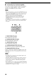
... and SP B is also possible to the corresponding SPEAKERS terminals. CONNECTIONS ■ Connecting to an external amplifier If you want to increase the power output to the speakers, or want to use another amplifier, connect an external amplifier to this unit to the maximum. • The signals...output from the SUBWOOFER PRE OUT jack depending on the subwoofer. Set the volume of the subwoofer with built-in amplifier, such as the YAMAHA Active Servo Processing Subwoofer System, to the PRE OUT jacks as the corresponding speaker terminals. • Adjust the volume level of the ...
... and SP B is also possible to the corresponding SPEAKERS terminals. CONNECTIONS ■ Connecting to an external amplifier If you want to increase the power output to the speakers, or want to use another amplifier, connect an external amplifier to this unit to the maximum. • The signals...output from the SUBWOOFER PRE OUT jack depending on the subwoofer. Set the volume of the subwoofer with built-in amplifier, such as the YAMAHA Active Servo Processing Subwoofer System, to the PRE OUT jacks as the corresponding speaker terminals. • Adjust the volume level of the ...
MCXSP10 Manual
Page 26
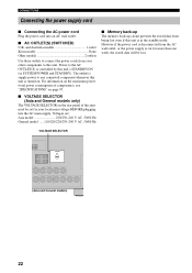
... be lost even if this unit's STANDBY/ON (or SYSTEM POWER and STANDBY). However if the power cord is disconnected from being lost . CONNECTIONS Connecting the power supply cord ■ Connecting the AC power cord Plug the power cord into the AC main supply. Power to the AC OUTLET(S) is controlled by this unit is cut...-240 V AC, 50/60 Hz ■ Memory back-up The memory back-up circuit prevents the stored data from the AC wall outlet, or the power supply is in the standby mode. VOLTAGE SELECTOR VOLTAGE SELECTOR (Asia and General models) 22 For information on the maximum...
... be lost even if this unit's STANDBY/ON (or SYSTEM POWER and STANDBY). However if the power cord is disconnected from being lost . CONNECTIONS Connecting the power supply cord ■ Connecting the AC power cord Plug the power cord into the AC main supply. Power to the AC OUTLET(S) is controlled by this unit is cut...-240 V AC, 50/60 Hz ■ Memory back-up The memory back-up circuit prevents the stored data from the AC wall outlet, or the power supply is in the standby mode. VOLTAGE SELECTOR VOLTAGE SELECTOR (Asia and General models) 22 For information on the maximum...

MCXSP10 Manual
Page 27
...CONNECTIONS Speaker impedance setting CAUTION If you made is reflected the next time this unit's power is in the front panel display. model) 1 CODE SET TRANSMIT POWER TV POWER AV STANDBY CD MD/CD-R TUNER SYSTEM POWER SLEEP DVD DTV/CBL V-AUX MULTI CH IN VCR 1 DVR/VCR2 AMP 1 TV ...VOL TV CH VOLUME TV MUTE TV INPUT 3 Press STRAIGHT (EFFECT) repeatedly to turn on the power. STRAIGHT EFFECT While holding down ,...
...CONNECTIONS Speaker impedance setting CAUTION If you made is reflected the next time this unit's power is in the front panel display. model) 1 CODE SET TRANSMIT POWER TV POWER AV STANDBY CD MD/CD-R TUNER SYSTEM POWER SLEEP DVD DTV/CBL V-AUX MULTI CH IN VCR 1 DVR/VCR2 AMP 1 TV ...VOL TV CH VOLUME TV MUTE TV INPUT 3 Press STRAIGHT (EFFECT) repeatedly to turn on the power. STRAIGHT EFFECT While holding down ,...
MCXSP10 Manual
Page 32
... panel. • Unplug the headphones. Only one presence channel signal is detected. • Connect the surround back speaker to the OPTIMIZER MIC jack on the power to user activity. Surround back speaker(s) is too loud. • Try the auto setup procedure in a quiet environment. • Turn off noisy electric equipment like...
... panel. • Unplug the headphones. Only one presence channel signal is detected. • Connect the surround back speaker to the OPTIMIZER MIC jack on the power to user activity. Surround back speaker(s) is too loud. • Try the auto setup procedure in a quiet environment. • Turn off noisy electric equipment like...

MCXSP10 Manual
Page 34
... STRAIGHT TONE CONTROL INPUT MODE MULTI CH INPUT PURE DIRECT EFFECT S VIDEO VIDEO AUX VIDEO L AUDIO R OPTICAL 13 7 4 6 1 4 3 CODE SET TRANSMIT POWER TV POWER AV STANDBY CD MD/CD-R TUNER SYSTEM POWER SLEEP DVD DTV/CBL V-AUX MULTI CH IN VCR 1 DVR/VCR2 AMP TV VOL TV CH VOLUME TV VOL TV CH VOLUME...
... STRAIGHT TONE CONTROL INPUT MODE MULTI CH INPUT PURE DIRECT EFFECT S VIDEO VIDEO AUX VIDEO L AUDIO R OPTICAL 13 7 4 6 1 4 3 CODE SET TRANSMIT POWER TV POWER AV STANDBY CD MD/CD-R TUNER SYSTEM POWER SLEEP DVD DTV/CBL V-AUX MULTI CH IN VCR 1 DVR/VCR2 AMP TV VOL TV CH VOLUME TV VOL TV CH VOLUME...
MCXSP10 Manual
Page 37
... remote control to select the AMP mode, then press EXTD SUR. BASIC OPERATION ■ Remote control operation AMP CODE SET TRANSMIT POWER TV POWER AV STANDBY CD MD/CD-R TUNER SYSTEM POWER SLEEP DVD DTV/CBL V-AUX MULTI CH IN VCR 1 DVR/VCR2 AMP TV VOL TV CH VOLUME TV MUTE TV INPUT TV...
... remote control to select the AMP mode, then press EXTD SUR. BASIC OPERATION ■ Remote control operation AMP CODE SET TRANSMIT POWER TV POWER AV STANDBY CD MD/CD-R TUNER SYSTEM POWER SLEEP DVD DTV/CBL V-AUX MULTI CH IN VCR 1 DVR/VCR2 AMP TV VOL TV CH VOLUME TV MUTE TV INPUT TV...

MCXSP10 Manual
Page 38
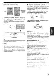
...) is turned off, this unit can also select a decoder by pressing j / i on multiple channels. When "2ch Stereo" or PURE DIRECT is selected. • When the power of this unit is set to select the MOVIE THEATER program.
...) is turned off, this unit can also select a decoder by pressing j / i on multiple channels. When "2ch Stereo" or PURE DIRECT is selected. • When the power of this unit is set to select the MOVIE THEATER program.


