Owner's Manual
Page 9
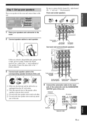
...short circuits. 3 Do not let the bare speaker wires touch each speaker cable to the corresponding speaker terminal of your speaker. Subwoofer AV receiver Input jack Subwoofer cable SUBWOOFER OUTPUT jack 5 En English INTRODUCTION Step 1: Set up your speakers Place your speakers and subwoofer in the... groove or ridge. COAXIAL OPTICAL SPEAKERS DVD IN1 DTV/CBL IN2 HDMI REMOTE IN OUT +12V 15mA MAX. Connect the plain cable to the "-" (black) terminals. 3 Connect each other. 4 Do not let the bare speaker wires touch any metal part of this unit. 4 Connect the subwoofer cable...
...short circuits. 3 Do not let the bare speaker wires touch each speaker cable to the corresponding speaker terminal of your speaker. Subwoofer AV receiver Input jack Subwoofer cable SUBWOOFER OUTPUT jack 5 En English INTRODUCTION Step 1: Set up your speakers Place your speakers and subwoofer in the... groove or ridge. COAXIAL OPTICAL SPEAKERS DVD IN1 DTV/CBL IN2 HDMI REMOTE IN OUT +12V 15mA MAX. Connect the plain cable to the "-" (black) terminals. 3 Connect each other. 4 Do not let the bare speaker wires touch any metal part of this unit. 4 Connect the subwoofer cable...
Owner's Manual
Page 15
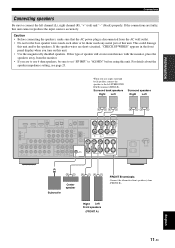
... speakers. PREPARATION Connections Connecting speakers Be sure to set "SP IMP." If this type of this unit. to the left channel (L), right channel (R), "+" (red) and "-" (black) properly. Surround back speakers Right Left Surround speakers Right Left COAXIAL OPTICAL SPEAKERS DVD IN1 DTV/CBL IN2 HDMI REMOTE IN OUT +12V 15mA MAX...
... speakers. PREPARATION Connections Connecting speakers Be sure to set "SP IMP." If this type of this unit. to the left channel (L), right channel (R), "+" (red) and "-" (black) properly. Surround back speakers Right Left Surround speakers Right Left COAXIAL OPTICAL SPEAKERS DVD IN1 DTV/CBL IN2 HDMI REMOTE IN OUT +12V 15mA MAX...
Owner's Manual
Page 16
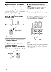
... connections, set "BI-AMP" to one speaker system. Front speakers Right Left ■ Connecting to the FRONT A terminals 2 1 Red: positive (+) Black: negative (-) 3 1 Loosen the knob. 2 Insert the bare end of insulated cables running side by side. Connections ■ Before connecting to the ...SPEAKERS terminal A speaker cord is a single-pole electrical connector widely used to the "-" (black) terminals. This unit allows you can not use the FRONT and SURROUND BACK terminals as shown below. Cables are put into the...
... connections, set "BI-AMP" to one speaker system. Front speakers Right Left ■ Connecting to the FRONT A terminals 2 1 Red: positive (+) Black: negative (-) 3 1 Loosen the knob. 2 Insert the bare end of insulated cables running side by side. Connections ■ Before connecting to the ...SPEAKERS terminal A speaker cord is a single-pole electrical connector widely used to the "-" (black) terminals. This unit allows you can not use the FRONT and SURROUND BACK terminals as shown below. Cables are put into the...
