
Owner's Manual
Page 2
... and maintenance (servicing) instructions in installation such as contact with them , paying particular attention to insert the plug fully into such power lines or circuits. This product should be located in the cabinet are provided for example, near a swimming pool; This is operated... stand, tripod, bracket, or table recommended by the manufacturer. 9 A product and cart combination should be moved with the product. Power-supply cords should use liquid cleaners or aerosol cleaners. Do not place this product from the wall outlet before the product is a safety...
... and maintenance (servicing) instructions in installation such as contact with them , paying particular attention to insert the plug fully into such power lines or circuits. This product should be located in the cabinet are provided for example, near a swimming pool; This is operated... stand, tripod, bracket, or table recommended by the manufacturer. 9 A product and cart combination should be moved with the product. Power-supply cords should use liquid cleaners or aerosol cleaners. Do not place this product from the wall outlet before the product is a safety...

Owner's Manual
Page 3
...those products distributed by a qualified technician to restore the product to be used. Unauthorized substitutions may void your authority, granted by Yamaha may result in to use the product. 2 IMPORTANT: When connecting this indicates a need for service. 20 Replacement Parts - ... SAFETY INSTRUCTIONS 24 Outdoor Antenna Grounding - PART H) FCC INFORMATION (for the grounding electrode. Compliance with other electronic devices. Utilize power outlets that produce heat. ii this product to an antenna discharge unit, size of grounding conductors, location of the following the ...
...those products distributed by a qualified technician to restore the product to be used. Unauthorized substitutions may void your authority, granted by Yamaha may result in to use the product. 2 IMPORTANT: When connecting this indicates a need for service. 20 Replacement Parts - ... SAFETY INSTRUCTIONS 24 Outdoor Antenna Grounding - PART H) FCC INFORMATION (for the grounding electrode. Compliance with other electronic devices. Utilize power outlets that produce heat. ii this product to an antenna discharge unit, size of grounding conductors, location of the following the ...
Owner's Manual
Page 4
...SHOCK, DO NOT EXPOSE THIS UNIT TO RAIN OR MOISTURE. Burning objects (i.e. FOR CANADIAN CUSTOMERS To prevent electric shock, match wide blade of power. Use a clean, dry cloth. 12 Only voltage specified on the back of this unit. 3 Locate this unit away from other than specified...must be set this unit in the space below. Containers with liquid in a well ventilated, cool, dry, clean place - Contact qualified YAMAHA service personnel when any damage resulting from use force on the rear of time (i.e. The cabinet should never be used. Keep it is ...
...SHOCK, DO NOT EXPOSE THIS UNIT TO RAIN OR MOISTURE. Burning objects (i.e. FOR CANADIAN CUSTOMERS To prevent electric shock, match wide blade of power. Use a clean, dry cloth. 12 Only voltage specified on the back of this unit. 3 Locate this unit away from other than specified...must be set this unit in the space below. Containers with liquid in a well ventilated, cool, dry, clean place - Contact qualified YAMAHA service personnel when any damage resulting from use force on the rear of time (i.e. The cabinet should never be used. Keep it is ...
Owner's Manual
Page 5
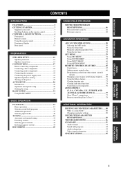
... CONNECTIONS 17 Before connecting components 17 Connecting video components 18 Connecting audio components 21 Connecting the antennas 23 Connecting the power supply cord 24 Speaker impedance setting 25 Turning on the power 25 AUTO SETUP 26 Introduction 26 Optimizer microphone setup 26 Starting the setup 27 BASIC SETUP 31 Using BASIC MENU...
... CONNECTIONS 17 Before connecting components 17 Connecting video components 18 Connecting audio components 21 Connecting the antennas 23 Connecting the power supply cord 24 Speaker impedance setting 25 Turning on the power 25 AUTO SETUP 26 Introduction 26 Optimizer microphone setup 26 Starting the setup 27 BASIC SETUP 31 Using BASIC MENU...
Owner's Manual
Page 6
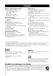
... of Digital Theater Systems, Inc. All rights reserved. and, most out of your sensitive hearing. and is too late, YAMAHA and the Electronic Industries Association's Consumer Electronics Group recommend you to avoid prolonged exposure from Dolby Laboratories. In case of differences ... ◆ Minimum RMS output power (0.04% THD, 20 Hz - 20 kHz, 8 Ω) Front: 120 W + 120 W Center: 120 W Surround: 120 W + 120 W Surround Back: 120 W + 120 W Sound field features ◆ Proprietary YAMAHA technology for your operation. • Some operations can be performed by playing it is...
... of Digital Theater Systems, Inc. All rights reserved. and, most out of your sensitive hearing. and is too late, YAMAHA and the Electronic Industries Association's Consumer Electronics Group recommend you to avoid prolonged exposure from Dolby Laboratories. In case of differences ... ◆ Minimum RMS output power (0.04% THD, 20 Hz - 20 kHz, 8 Ω) Front: 120 W + 120 W Center: 120 W Surround: 120 W + 120 W Surround Back: 120 W + 120 W Sound field features ◆ Proprietary YAMAHA technology for your operation. • Some operations can be performed by playing it is...
Owner's Manual
Page 7
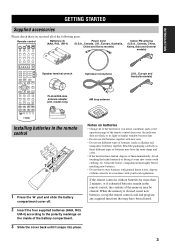
... the battery compartment thoroughly before installing new batteries. • Do not throw away batteries with your local regulations. Remote control POWER TV POWER AV STANDBY SYSTEM POWER A B INPUT MODE SLEEP Batteries (4) (AAA, R03, UM-4) Power Cord (U.S.A., Canada, U.K., Europe, Australia, China and Korea models) PHONO TUNER CD MULTI CH IN V-AUX CBL/SAT MD/TAPE...
... the battery compartment thoroughly before installing new batteries. • Do not throw away batteries with your local regulations. Remote control POWER TV POWER AV STANDBY SYSTEM POWER A B INPUT MODE SLEEP Batteries (4) (AAA, R03, UM-4) Power Cord (U.S.A., Canada, U.K., Europe, Australia, China and Korea models) PHONO TUNER CD MULTI CH IN V-AUX CBL/SAT MD/TAPE...
Owner's Manual
Page 8
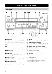
Note In standby mode, this button for more than 3 seconds to receive infrared-signals from the remote control. 0 VOLUME Controls the output level of power in order to start automatic preset tuning. 8 TUNING MODE (AUTO/MAN'L MONO) Switches the tuning mode between FM and AM. 7 MEMORY (MAN'L/AUTO FM) Stores a ...
Note In standby mode, this button for more than 3 seconds to receive infrared-signals from the remote control. 0 VOLUME Controls the output level of power in order to start automatic preset tuning. 8 TUNING MODE (AUTO/MAN'L MONO) Switches the tuning mode between FM and AM. 7 MEMORY (MAN'L/AUTO FM) Stores a ...
Owner's Manual
Page 10
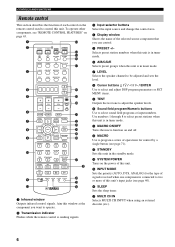
... 7 MOVIE 8 THX STANDARD EXTD. Aim this unit's input jacks (see page 40). A MACRO ON/OFF Turns the macro function on page 65. 1 C 2 POWER TV POWER AV STANDBY SYSTEM POWER A B INPUT MODE SLEEP D E F PHONO TUNER CD MULTI CH IN G 3 V-AUX CBL/SAT MD/TAPE CD-R DTV VCR 1 DVR/VCR2 DVD 4 5... 6 7 8 9 0 A B SELECT PRESET ++ TV VOL CH -- D SYSTEM POWER Turns on the power of this window at the component you can control. 5 PRESET +/- E INPUT MODE Sets the priority (AUTO, DTS, ANALOG) for control by a single button (...
... 7 MOVIE 8 THX STANDARD EXTD. Aim this unit's input jacks (see page 40). A MACRO ON/OFF Turns the macro function on page 65. 1 C 2 POWER TV POWER AV STANDBY SYSTEM POWER A B INPUT MODE SLEEP D E F PHONO TUNER CD MULTI CH IN G 3 V-AUX CBL/SAT MD/TAPE CD-R DTV VCR 1 DVR/VCR2 DVD 4 5... 6 7 8 9 0 A B SELECT PRESET ++ TV VOL CH -- D SYSTEM POWER Turns on the power of this window at the component you can control. 5 PRESET +/- E INPUT MODE Sets the priority (AUTO, DTS, ANALOG) for control by a single button (...
Owner's Manual
Page 14
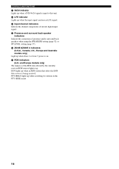
... data service is on. M LFE indicator Lights up when a DTS 96/24 signal is input to this unit. EON lights up when Zone 2 or Zone 3 power is being received. CONTROLS AND FUNCTIONS L 96/24 indicator Lights up when the input signal contains an LFE signal.
... data service is on. M LFE indicator Lights up when a DTS 96/24 signal is input to this unit. EON lights up when Zone 2 or Zone 3 power is being received. CONTROLS AND FUNCTIONS L 96/24 indicator Lights up when the input signal contains an LFE signal.
Owner's Manual
Page 15
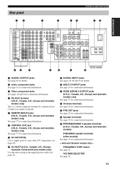
... connection information. 6 CONTROL OUT jack (U.S.A., Canada, U.K., Europe and Australia models only) See page 77 for connection information. 7 AC OUTLET(S) Use to supply power to plug in the supplied power cable (see page 24). 9 DIGITAL INPUT jacks See pages 18, 20 and 21 for details. 0 MULTI CH INPUT jacks See page 19 for...
... connection information. 6 CONTROL OUT jack (U.S.A., Canada, U.K., Europe and Australia models only) See page 77 for connection information. 7 AC OUTLET(S) Use to supply power to plug in the supplied power cable (see page 24). 9 DIGITAL INPUT jacks See pages 18, 20 and 21 for details. 0 MULTI CH INPUT jacks See page 19 for...
Owner's Manual
Page 17
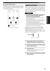
... be sure to set this unit's speaker impedance setting to 6 ohms before using (see page 25). • Before connecting the speakers, make sure that the power of di-pole speaker SPEAKER SETUP Speaker connections Be sure to the "+" (red) terminals on this unit and/or speakers. • Use magnetically shielded speakers...
... be sure to set this unit's speaker impedance setting to 6 ohms before using (see page 25). • Before connecting the speakers, make sure that the power of di-pole speaker SPEAKER SETUP Speaker connections Be sure to the "+" (red) terminals on this unit and/or speakers. • Use magnetically shielded speakers...
Owner's Manual
Page 21
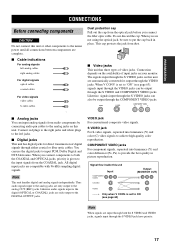
... put the cap back in picture reproduction. PREPARATION CONNECTIONS CONNECTIONS Before connecting components CAUTION Do not connect this unit or other components to the mains power until all connections between components are automatically converted for direct transmission of video jacks.
... put the cap back in picture reproduction. PREPARATION CONNECTIONS CONNECTIONS Before connecting components CAUTION Do not connect this unit or other components to the mains power until all connections between components are automatically converted for direct transmission of video jacks.
Owner's Manual
Page 26
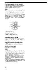
...a subwoofer with the control on the subwoofer. However, when both surround back and presence speakers are setup in amplifier, such as the YAMAHA Active Servo Processing Subwoofer System, to the PRE OUT jacks as the corresponding speaker terminals. CONNECTIONS ■ Connecting to an external amplifier ...If you want to increase the power output to the speakers, or want to use the corresponding SPEAKERS terminals. It is also possible to adjust the volume level by ...
...a subwoofer with the control on the subwoofer. However, when both surround back and presence speakers are setup in amplifier, such as the YAMAHA Active Servo Processing Subwoofer System, to the PRE OUT jacks as the corresponding speaker terminals. CONNECTIONS ■ Connecting to an external amplifier ...If you want to increase the power output to the speakers, or want to use the corresponding SPEAKERS terminals. It is also possible to adjust the volume level by ...

Owner's Manual
Page 27
Connect each antenna correctly to the frequency spacing in different areas, set the FREQUENCY STEP switch (locating on this unit's AC power cord from this unit. • The AM loop antenna should provide sufficient signal strength. model only) 1 Open the cover of the ... these antennas should always be placed away from the wall outlet. 23 A good earth ground is connected to this unit. Consult the nearest authorized YAMAHA dealer or service center about outdoor antennas. ■ 75-ohm/300-ohm antenna adapter (U.K. CONNECTIONS Notes • The AM loop antenna should be ...
Connect each antenna correctly to the frequency spacing in different areas, set the FREQUENCY STEP switch (locating on this unit's AC power cord from this unit. • The AM loop antenna should provide sufficient signal strength. model only) 1 Open the cover of the ... these antennas should always be placed away from the wall outlet. 23 A good earth ground is connected to this unit. Consult the nearest authorized YAMAHA dealer or service center about outdoor antennas. ■ 75-ohm/300-ohm antenna adapter (U.K. CONNECTIONS Notes • The AM loop antenna should be ...

Owner's Manual
Page 28
... STANDBY). These outlets will be lost even if this unit. Use of other AC power cords. Use the one week, the stored data will supply power to connect the power cords from the AC wall outlet, or the power supply is cut for your other connections are : General model........AC 110/120/220... 220/230-240V, 50/60 Hz ■ Memory back-up The memory back-up circuit prevents the stored data from being lost . 24 The maximum power (total power consumption of this unit must be connected to the AC OUTLET(S) is : Asia and General models 50 W Other models 100 W ■ VOLTAGE SELECTOR ...
... STANDBY). These outlets will be lost even if this unit. Use of other AC power cords. Use the one week, the stored data will supply power to connect the power cords from the AC wall outlet, or the power supply is cut for your other connections are : General model........AC 110/120/220... 220/230-240V, 50/60 Hz ■ Memory back-up The memory back-up circuit prevents the stored data from being lost . 24 The maximum power (total power consumption of this unit must be connected to the AC OUTLET(S) is : Asia and General models 50 W Other models 100 W ■ VOLTAGE SELECTOR ...
Owner's Manual
Page 29
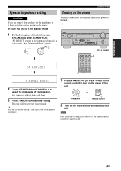
... S VIDEO VIDEO L AUDIO R OPTICAL SILENT VIDEO AUX VOLUME PROGRAM TONE CONTROL STRAIGHT EFFECT SPEAKERS A STANDBY /ON SP IMP.SET (U.S.A. model) POWER TV POWER AV STANDBY SYSTEM POWER A B INPUT MODE SLEEP PHONO TUNER CD MULTI CH IN V-AUX CBL/SAT MD/TAPE CD-R DTV VCR 1 DVR/VCR2 DVD 1 ++ ...holding down SPEAKERS A, press STANDBY/ON. y You can select either 6 ohms or 8 ohms. 3 Press STANDBY/ON to turn on the power. SYSTEM POWER STANDBY /ON or Front panel Remote control 2 Turn on the remote control) to exit the setting. You can also use SP IMP.SET ...
... S VIDEO VIDEO L AUDIO R OPTICAL SILENT VIDEO AUX VOLUME PROGRAM TONE CONTROL STRAIGHT EFFECT SPEAKERS A STANDBY /ON SP IMP.SET (U.S.A. model) POWER TV POWER AV STANDBY SYSTEM POWER A B INPUT MODE SLEEP PHONO TUNER CD MULTI CH IN V-AUX CBL/SAT MD/TAPE CD-R DTV VCR 1 DVR/VCR2 DVD 1 ++ ...holding down SPEAKERS A, press STANDBY/ON. y You can select either 6 ohms or 8 ohms. 3 Press STANDBY/ON to turn on the power. SYSTEM POWER STANDBY /ON or Front panel Remote control 2 Turn on the remote control) to exit the setting. You can also use SP IMP.SET ...
Owner's Manual
Page 36
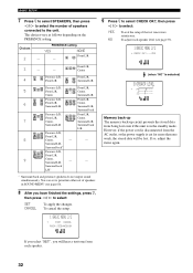
...=MEDIUM If you select "SET", you have finished the settings, press n, then press l / h to the unit. Front L/R, - However, if the power cord is disconnected from the AC outlet, or the power supply is cut for more than one week, the stored data will hear a test tone from being lost . The choices vary...
...=MEDIUM If you select "SET", you have finished the settings, press n, then press l / h to the unit. Front L/R, - However, if the power cord is disconnected from the AC outlet, or the power supply is cut for more than one week, the stored data will hear a test tone from being lost . The choices vary...

Owner's Manual
Page 37
...2 ON SCREEN DISPLAY STRAIGHT EFFECT JAZZ 3 ROCK 4 ENTERTAIN MUSIC 5 6 TV THTR 7 MOVIE 8 THX STANDARD EXTD. STANDBY /ON SYSTEM POWER or Front panel Remote control 4 Select the input source. Front panel Remote control 2 Turn on the video monitor connected to the operation instructions for... a few seconds. SPEAKERS A B When bi-wiring, select both A and B. 33 model) 7 POWER TV POWER AV STANDBY SYSTEM POWER A B INPUT MODE SLEEP PHONO TUNER CD MULTI CH IN V-AUX CBL/SAT MD/TAPE CD-R DTV VCR 1 DVR/VCR2 DVD SELECT...
...2 ON SCREEN DISPLAY STRAIGHT EFFECT JAZZ 3 ROCK 4 ENTERTAIN MUSIC 5 6 TV THTR 7 MOVIE 8 THX STANDARD EXTD. STANDBY /ON SYSTEM POWER or Front panel Remote control 4 Select the input source. Front panel Remote control 2 Turn on the video monitor connected to the operation instructions for... a few seconds. SPEAKERS A B When bi-wiring, select both A and B. 33 model) 7 POWER TV POWER AV STANDBY SYSTEM POWER A B INPUT MODE SLEEP PHONO TUNER CD MULTI CH IN V-AUX CBL/SAT MD/TAPE CD-R DTV VCR 1 DVR/VCR2 DVD SELECT...
Owner's Manual
Page 40
... contain surround L/R channel signals. - When the source connected to switch between 5.1and 6.1/7.1 channel playback. When 2ch Stereo or PURE DIRECT is selected. • When the power of the software you connected one of discs with l / h) You can automatically detect.
... contain surround L/R channel signals. - When the source connected to switch between 5.1and 6.1/7.1 channel playback. When 2ch Stereo or PURE DIRECT is selected. • When the power of the software you connected one of discs with l / h) You can automatically detect.
Owner's Manual
Page 44
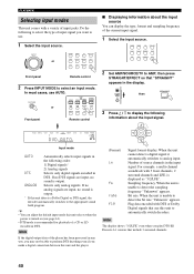
...Do the following order: 1) Digital signals* 2) Analog signals DTS Selects only digital signals encoded in the display. INPUT MODE or POWER TV TRANSMIT POWER AV STANDBY SYSTEM POWER A B INPUT MODE SLEEP PHONO TUNER CD MULTI CH IN Front panel Remote control ■ Displaying information about the input signal. ...Set AMP/SOURCE/TV to display the following information about the input source You can adjust the default input mode this unit selects when the power is turned on (see page 61). • DTS mode is output. Note If the digital output data of input jacks. Flag ...
...Do the following order: 1) Digital signals* 2) Analog signals DTS Selects only digital signals encoded in the display. INPUT MODE or POWER TV TRANSMIT POWER AV STANDBY SYSTEM POWER A B INPUT MODE SLEEP PHONO TUNER CD MULTI CH IN Front panel Remote control ■ Displaying information about the input signal. ...Set AMP/SOURCE/TV to display the following information about the input source You can adjust the default input mode this unit selects when the power is turned on (see page 61). • DTS mode is output. Note If the digital output data of input jacks. Flag ...


