

Owner's Manual
Page 2
... frequencies and, if not installed and used . If this product or the device that is 300 ohm ribbon lead, change the lead-in the users manual, may void your FCC authorization to products distributed by Yamaha Corporation of product. If the antenna lead-in accordance with.... 4 Follow all installation instructions. If you can be the source of interference, which can not locate the appropriate retailer, please contact Yamaha Corporation of America, Electronic Service Division, 6600 Orangethorpe Ave, Buena Park, CA90620 The above warning is damaged, liquid has been spilled or...
... frequencies and, if not installed and used . If this product or the device that is 300 ohm ribbon lead, change the lead-in the users manual, may void your FCC authorization to products distributed by Yamaha Corporation of product. If the antenna lead-in accordance with.... 4 Follow all installation instructions. If you can be the source of interference, which can not locate the appropriate retailer, please contact Yamaha Corporation of America, Electronic Service Division, 6600 Orangethorpe Ave, Buena Park, CA90620 The above warning is damaged, liquid has been spilled or...
Owner's Manual
Page 4
...to , the following : Power supply/Power cord • Use only the specified power supply (PW800W or an equivalent recommended by Yamaha). • Only use the voltage specified as a bookcase or closet. • Do not use immediately and have the device inspected by qualified... Yamaha service personnel. • If this manual in a safe place for...
...to , the following : Power supply/Power cord • Use only the specified power supply (PW800W or an equivalent recommended by Yamaha). • Only use the voltage specified as a bookcase or closet. • Do not use immediately and have the device inspected by qualified... Yamaha service personnel. • If this manual in a safe place for...
Owner's Manual
Page 5
... deteriorates over time. The performance of time at a high or uncomfortable volume level, since this case, have the device inspected by improper use the headphones for all devices, set all devices. Connections • Before connecting the device to other devices, turn the power off when ... battery fully discharges, this happens, turn off the power for damage caused by qualified Yamaha service personnel. • Do not use or modifications to minimum. Yamaha cannot be lost or destroyed. Always turn off the power immediately and unplug the power cord from...
... deteriorates over time. The performance of time at a high or uncomfortable volume level, since this case, have the device inspected by improper use the headphones for all devices, set all devices. Connections • Before connecting the device to other devices, turn the power off when ... battery fully discharges, this happens, turn off the power for damage caused by qualified Yamaha service personnel. • Do not use or modifications to minimum. Yamaha cannot be lost or destroyed. Always turn off the power immediately and unplug the power cord from...
Owner's Manual
Page 6
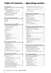
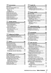
...53 Operations in the STEREO A/B channel strip 54 MATRIX section 55 Items in the MATRIX section 55 Operations in the MATRIX section 55 7 Using the Selected Channel section ...57 About the SELECTED CHANNEL section 57 Items in the SELECTED CHANNEL section 57 GROUP 57 CHANNEL SELECT 58 DELAY ...in the DCA strip 73 Using DCA Groups 74 Assigning channels to DCA groups 74 Controlling DCA groups 75 Using mute groups 75 Assigning channels to mute groups 75 Controlling mute groups 76 Using the Mute Safe function 76 Using EQ Link and Compressor Link 77 6 PM5D/PM5D-RH Owner's Manual Table ...
...53 Operations in the STEREO A/B channel strip 54 MATRIX section 55 Items in the MATRIX section 55 Operations in the MATRIX section 55 7 Using the Selected Channel section ...57 About the SELECTED CHANNEL section 57 Items in the SELECTED CHANNEL section 57 GROUP 57 CHANNEL SELECT 58 DELAY ...in the DCA strip 73 Using DCA Groups 74 Assigning channels to DCA groups 74 Controlling DCA groups 75 Using mute groups 75 Assigning channels to mute groups 75 Controlling mute groups 76 Using the Mute Safe function 76 Using EQ Link and Compressor Link 77 6 PM5D/PM5D-RH Owner's Manual Table ...
Owner's Manual
Page 7
...121 Transmitting MIDI events when you switch scenes ...122 Using GPI (General Purpose Interface 123 Using GPI IN 123 Calibrating the GPI IN ports 125 Using GPI OUT 126 17 Using memory cards 128 Using memory cards with the PM5D 128 Saving files to a memory card 128 Loading files...connections 143 Basic settings for cascade connection 143 Selecting the buses used for cascade connection 144 Connecting the PM5D to a computer via USB ..........146 Caution when using the USB TO HOST connector ........ 146 Initializing the PM5D's internal memory 147 Adjusting the faders and input/output gain ...
...121 Transmitting MIDI events when you switch scenes ...122 Using GPI (General Purpose Interface 123 Using GPI IN 123 Calibrating the GPI IN ports 125 Using GPI OUT 126 17 Using memory cards 128 Using memory cards with the PM5D 128 Saving files to a memory card 128 Loading files...connections 143 Basic settings for cascade connection 143 Selecting the buses used for cascade connection 144 Connecting the PM5D to a computer via USB ..........146 Caution when using the USB TO HOST connector ........ 146 Initializing the PM5D's internal memory 147 Adjusting the faders and input/output gain ...
Owner's Manual
Page 10
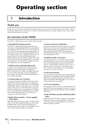
... quick and intuitive operation just as scene saving and recall can also be installed to four PM5D units, or one PM5D and one Yamaha DM2000/02R96 unit, can be used in memory as reverb, delay, multiband compressor, and various modulation effects can be routed via a cascade connection. ❏ Surround panning Surround pan functionality allows...
... quick and intuitive operation just as scene saving and recall can also be installed to four PM5D units, or one PM5D and one Yamaha DM2000/02R96 unit, can be used in memory as reverb, delay, multiband compressor, and various modulation effects can be routed via a cascade connection. ❏ Surround panning Surround pan functionality allows...
Owner's Manual
Page 11
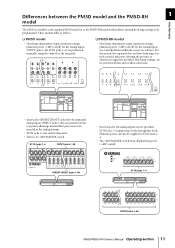
...; The +48V MASTER switch turns all phantom power (+48V) on /off . INSERT IN/OUT jacks 1-48 ST IN jacks 1-4 INPUT jacks 1-48 PM5D/PM5D-RH Owner's Manual Operating section 11 For this reason, the top panel does not have head amp controls; instead, indicators showing the presence or absence... and the PM5D-RH 1 model Introduction The PM5D is no +48V MASTER switch. ST IN jacks 1-4 INPUT jacks 1-48 • Insert jacks for the analog inputs (INPUT jacks 1-48, ST IN jacks 1-4) are performed manually, using the controls of a signal are not provided. • ST IN jacks 1-4 support...
...; The +48V MASTER switch turns all phantom power (+48V) on /off . INSERT IN/OUT jacks 1-48 ST IN jacks 1-4 INPUT jacks 1-48 PM5D/PM5D-RH Owner's Manual Operating section 11 For this reason, the top panel does not have head amp controls; instead, indicators showing the presence or absence... and the PM5D-RH 1 model Introduction The PM5D is no +48V MASTER switch. ST IN jacks 1-4 INPUT jacks 1-48 • Insert jacks for the analog inputs (INPUT jacks 1-48, ST IN jacks 1-4) are performed manually, using the controls of a signal are not provided. • ST IN jacks 1-4 support...
Owner's Manual
Page 12
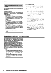
...clock is called "word clock." Regarding word clock synchronization The signal used as sends to STEREO OUT jacks A/B. Be aware that contains a sampling rate converter, or via the 2TR IN/OUT DIGITAL jacks. 12 PM5D/PM5D-RH Owner's Manual Operating section Hint • For details on ...to process stereo signals. Normally, the same signal is also possible to use the STEREO B channel as follows. • Input channels 1-48 These channels are used to MIX buses, and output them from an external device via the PM5D's digital input/output jacks or via a digital I /O card installed...
...clock is called "word clock." Regarding word clock synchronization The signal used as sends to STEREO OUT jacks A/B. Be aware that contains a sampling rate converter, or via the 2TR IN/OUT DIGITAL jacks. 12 PM5D/PM5D-RH Owner's Manual Operating section Hint • For details on ...to process stereo signals. Normally, the same signal is also possible to use the STEREO B channel as follows. • Input channels 1-48 These channels are used to MIX buses, and output them from an external device via the PM5D's digital input/output jacks or via a digital I /O card installed...
Owner's Manual
Page 15
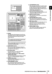
...IN channels 1-4 or FX RTN channels 1-4 (➥ p.39). R USER DEFINED KEYS sections This section executes the functions that will be used when you assign mute groups and DCA groups for mute groups 1-8 are also performed in / Effect return) channel strip section This section... the principal parameters of the STEREO A/B channels (➥ p.53). Mute operations for control from the MONITOR OUT jacks, and adjusts the lev- PM5D/PM5D-RH Owner's Manual Operating section 15 els. T ASSIGN MODE section This section lets you press a [CUE] key for input and output channels ...
...IN channels 1-4 or FX RTN channels 1-4 (➥ p.39). R USER DEFINED KEYS sections This section executes the functions that will be used when you assign mute groups and DCA groups for mute groups 1-8 are also performed in / Effect return) channel strip section This section... the principal parameters of the STEREO A/B channels (➥ p.53). Mute operations for control from the MONITOR OUT jacks, and adjusts the lev- PM5D/PM5D-RH Owner's Manual Operating section 15 els. T ASSIGN MODE section This section lets you press a [CUE] key for input and output channels ...
Owner's Manual
Page 17
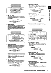
Use the dedicated cable included with a GPI-equipped external device. Nominal output level is +4 dBu. PM5D/PM5D-RH Owner's Manual Operating section 17 For details, contact your Yamaha dealer. Female XLR plug 2 (hot) 3 (cold) 1 (ground) N VUT X Y R L R L IN SMPTE USB OUT IN 75 ON OFF 2 1 2 1...XLR plug 2 (hot) 3 (cold) 1 (ground) H LAMP connector This is a D-sub 25-pin female connector that allows communication with the PM5D to make the connection. Female XLR plug 2 (hot) 3 (cold) 1 (ground) Note Although the various output jacks and 2TR IN ANALOG jacks...
Use the dedicated cable included with a GPI-equipped external device. Nominal output level is +4 dBu. PM5D/PM5D-RH Owner's Manual Operating section 17 For details, contact your Yamaha dealer. Female XLR plug 2 (hot) 3 (cold) 1 (ground) N VUT X Y R L R L IN SMPTE USB OUT IN 75 ON OFF 2 1 2 1...XLR plug 2 (hot) 3 (cold) 1 (ground) H LAMP connector This is a D-sub 25-pin female connector that allows communication with the PM5D to make the connection. Female XLR plug 2 (hot) 3 (cold) 1 (ground) Note Although the various output jacks and 2TR IN ANALOG jacks...
Owner's Manual
Page 18
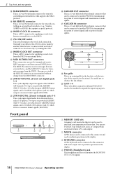
...exhaust. U 75Ω ON/OFF switch This switch terminates the word clock connection. Messages received at the MIDI IN connector are used to another PM5D for transmission/ reception of control signals and reception of audio signals. X 2TR OUT DIGITAL (2 track out digital) jacks 1-3 These...-pitch 68-pin female connector that can be received correctly, try turning this OFF. Be careful not to another PM5D for remotely controlling an external head amp device (e.g., Yamaha AD8HR or AD824) that supports a special protocol. 2 Top, front, and rear panels R RS422 REMOTE connector ...
...exhaust. U 75Ω ON/OFF switch This switch terminates the word clock connection. Messages received at the MIDI IN connector are used to another PM5D for transmission/ reception of control signals and reception of audio signals. X 2TR OUT DIGITAL (2 track out digital) jacks 1-3 These...-pitch 68-pin female connector that can be received correctly, try turning this OFF. Be careful not to another PM5D for remotely controlling an external head amp device (e.g., Yamaha AD8HR or AD824) that supports a special protocol. 2 Top, front, and rear panels R RS422 REMOTE connector ...
Owner's Manual
Page 19
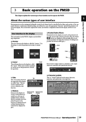
...off are displayed at left of the display are displayed in red or blue); User interface in the display The user interface in the PM5D's display uses the following components. ❏ Pointer The arrow shown in the display is selected for which / buttons are displayed in gray. If ... edit the parameter values in the display. 3 Basic operation on the PM5D This chapter explains the various types of user interface used to operate the PM5D. 3 About the various types of user interface Basic operation on the PM5D Basic parameters such as mixing and editing the sound of each channel can...
...off are displayed at left of the display are displayed in red or blue); User interface in the display The user interface in the PM5D's display uses the following components. ❏ Pointer The arrow shown in the display is selected for which / buttons are displayed in gray. If ... edit the parameter values in the display. 3 Basic operation on the PM5D This chapter explains the various types of user interface used to operate the PM5D. 3 About the various types of user interface Basic operation on the PM5D Basic parameters such as mixing and editing the sound of each channel can...
Owner's Manual
Page 20
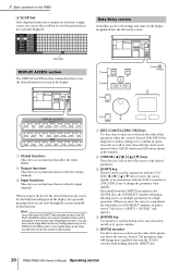
...of the parameter where the cursor is located. 3 Basic operation on /off, or to edit settings and values in that affect the entire PM5D. When you can be used to move the cursor to increase or decrease the value of the CANCEL button and OK button shown in the window. If you... a window asking you turn the [DATA] encoder while holding down the [SHIFT] key. 20 PM5D/PM5D-RH Owner's Manual Operating section E [DATA] encoder Use this key to switch a button at the cursor location on the PM5D ❏ Scroll bar If the displayed items are too numerous to fit into the data entry section...
...of the parameter where the cursor is located. 3 Basic operation on /off, or to edit settings and values in that affect the entire PM5D. When you can be used to move the cursor to increase or decrease the value of the CANCEL button and OK button shown in the window. If you... a window asking you turn the [DATA] encoder while holding down the [SHIFT] key. 20 PM5D/PM5D-RH Owner's Manual Operating section E [DATA] encoder Use this key to switch a button at the cursor location on the PM5D ❏ Scroll bar If the displayed items are too numerous to fit into the data entry section...
Owner's Manual
Page 21
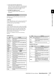
...jack for connecting a set of the character palette Same function as the [ENTER] key (when off) PM5D/PM5D-RH Owner's Manual Operating section 21 Function Input a scene number (if the PREFERENCE 1 screen item USE NUMERIC-KEYPAD is on), input numerical values (if off) Returns the scene selection number to the number ... Switches to the next screen within the same function Key Function + Switches to input characters, numerals, and symbols. The numeric key pad of the PM5D and used in the same way as the character palette in the display, hold down the left /right buttons These are...
...jack for connecting a set of the character palette Same function as the [ENTER] key (when off) PM5D/PM5D-RH Owner's Manual Operating section 21 Function Input a scene number (if the PREFERENCE 1 screen item USE NUMERIC-KEYPAD is on), input numerical values (if off) Returns the scene selection number to the number ... Switches to the next screen within the same function Key Function + Switches to input characters, numerals, and symbols. The numeric key pad of the PM5D and used in the same way as the character palette in the display, hold down the left /right buttons These are...
Owner's Manual
Page 22
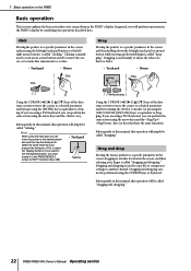
... left/ right mouse button) is called "dragging." Dragging and dropping cannot be called "dragging and dropping." Clicking is mainly used to turn an on-screen button on the PM5D Basic operation This section explains the basic procedures you must enable it in the PREFERENCE 2 screen (UTILITY function) (➥... the left button. (This is called the Tapping function.) If you want to use the tapping function, you can perform in the PM5D's display. If you are using a PS/2 keyboard, you will simply be performed using the arrow keys and the / keys (or keys that have the same function)....
... left/ right mouse button) is called "dragging." Dragging and dropping cannot be called "dragging and dropping." Clicking is mainly used to turn an on-screen button on the PM5D Basic operation This section explains the basic procedures you must enable it in the PREFERENCE 2 screen (UTILITY function) (➥... the left button. (This is called the Tapping function.) If you want to use the tapping function, you can perform in the PM5D's display. If you are using a PS/2 keyboard, you will simply be performed using the arrow keys and the / keys (or keys that have the same function)....
Owner's Manual
Page 23
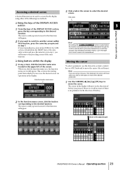
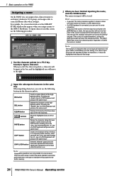
...Move to move if there is the starting point from which you pressed. Up to the desired function. When you click on the PM5D ❏ Using the keys of the DISPLAY ACCESS section 1 From the keys of that function will not move the cursor (the red frame). This ...seconds (not including the function menu). Click the function name area Moving the cursor To select a parameter, use the data entry section's controllers or a PS/2 keyboard to the adjacent grid PM5D/PM5D-RH Owner's Manual Operating section 23 The cursor in the display will appear. Accessing a desired screen A ...
...Move to move if there is the starting point from which you pressed. Up to the desired function. When you click on the PM5D ❏ Using the keys of the DISPLAY ACCESS section 1 From the keys of that function will not move the cursor (the red frame). This ...seconds (not including the function menu). Click the function name area Moving the cursor To select a parameter, use the data entry section's controllers or a PS/2 keyboard to the adjacent grid PM5D/PM5D-RH Owner's Manual Operating section 23 The cursor in the display will appear. Accessing a desired screen A ...
Owner's Manual
Page 24
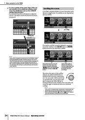
... encoder counterclockwise, the screen will scroll toward the left . Scrolling the screen A scroll bar is displayed if there are holding down the [SHIFT] key and use the CURSOR keys. Hint If the cursor is located at the ends of the scroll bar. If you move from the scroll window in which... you turn the encoder. 24 PM5D/PM5D-RH Owner's Manual Operating section If you pressed. 3 Basic operation on the direction in which the cursor is currently located, in the direction of the...
... encoder counterclockwise, the screen will scroll toward the left . Scrolling the screen A scroll bar is displayed if there are holding down the [SHIFT] key and use the CURSOR keys. Hint If the cursor is located at the ends of the scroll bar. If you move from the scroll window in which... you turn the encoder. 24 PM5D/PM5D-RH Owner's Manual Operating section If you pressed. 3 Basic operation on the direction in which the cursor is currently located, in the direction of the...
Owner's Manual
Page 25
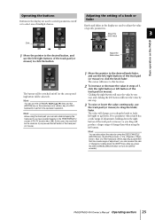
...encoder, or the / keys of a PS/2 keyboard. For a parameter whose knob has a wide range of adjustment, holding down . PM5D/PM5D-RH Owner's Manual Operating section 25 Hint When using the track pad, you press the [DEC/CANCEL]/[INC/OK] keys (or turn the [DATA] encoder). Hint You can increase the... rate of the track pad (or mouse). Adjusting the setting of a knob or fader Knobs and faders in the display are used to adjust the value of a PS/2 keyboard) to perform the equivalent operation. When adjusting a parameter that location. 2 To increase or ...
...encoder, or the / keys of a PS/2 keyboard. For a parameter whose knob has a wide range of adjustment, holding down . PM5D/PM5D-RH Owner's Manual Operating section 25 Hint When using the track pad, you press the [DEC/CANCEL]/[INC/OK] keys (or turn the [DATA] encoder). Hint You can increase the... rate of the track pad (or mouse). Adjusting the setting of a knob or fader Knobs and faders in the display are used to adjust the value of a PS/2 keyboard) to perform the equivalent operation. When adjusting a parameter that location. 2 To increase or ...
Owner's Manual
Page 26
... characters by the COPY button. You cannot input more than the specified number of characters, or move the highlighted area beyond that range. 1 Use the character palette (or a PS/2 keyboard) to left or right. Pressing the key of character string copied to buffer memory by turning the...key of a PS/2 keyboard will produce the same result. PASTE button Pastes the character string that was copied to the buffer memory. 26 PM5D/PM5D-RH Owner's Manual Operating section Hint • In general, the same procedure applies in some screens. There are not possible in screens where ...
... characters by the COPY button. You cannot input more than the specified number of characters, or move the highlighted area beyond that range. 1 Use the character palette (or a PS/2 keyboard) to left or right. Pressing the key of character string copied to buffer memory by turning the...key of a PS/2 keyboard will produce the same result. PASTE button Pastes the character string that was copied to the buffer memory. 26 PM5D/PM5D-RH Owner's Manual Operating section Hint • In general, the same procedure applies in some screens. There are not possible in screens where ...
Owner's Manual
Page 27
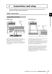
... the patching to its default state ➥ p.32) PM5D/PM5D-RH Owner's Manual Operating section 27 INPUT jacks 1-48 and ST IN jacks 1-4 can be changed if desired. (For details on /off are used mainly to connect microphones or monaural line-level devices. However..., this can both be used mainly to connect stereo line-level devices. Audio connections 4 Analog audio connections PM5D model Synthesizer Microphone PM5D-RH model Synthesizer Microphone Microphone Connections and setup Effect processor INPUT jacks 1-48...
... the patching to its default state ➥ p.32) PM5D/PM5D-RH Owner's Manual Operating section 27 INPUT jacks 1-48 and ST IN jacks 1-4 can be changed if desired. (For details on /off are used mainly to connect microphones or monaural line-level devices. However..., this can both be used mainly to connect stereo line-level devices. Audio connections 4 Analog audio connections PM5D model Synthesizer Microphone PM5D-RH model Synthesizer Microphone Microphone Connections and setup Effect processor INPUT jacks 1-48...


