
Owner's Manual
Page 1
DIGITAL MIXING CONSOLE PM5D / PM5D-RH Owner's Manual
DIGITAL MIXING CONSOLE PM5D / PM5D-RH Owner's Manual
Owner's Manual
Page 6
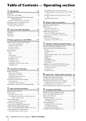
... Operating section 1 Introduction 10 Thank you 10 An overview of the PM5D 10 Differences between the PM5D model and the PM5D-RH model 11 About the channel structure of the PM5D 12 Regarding word clock synchronization 12 How this manual is organized 13 Conventions in this manual 13 2 Top, front, and rear panels 14 Top panel 14...
... Operating section 1 Introduction 10 Thank you 10 An overview of the PM5D 10 Differences between the PM5D model and the PM5D-RH model 11 About the channel structure of the PM5D 12 Regarding word clock synchronization 12 How this manual is organized 13 Conventions in this manual 13 2 Top, front, and rear panels 14 Top panel 14...
Owner's Manual
Page 7
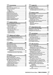
...MODE section 139 Assigning channels to DCA faders 139 Controlling the channels assigned to DCA faders 140 Locking the PM5D (Security functions 141 Setting the System Password or Console Password.......... 141 Using Parameter Lock or Console Lock ...PM5D to a computer via USB ..........146 Caution when using the USB TO HOST connector ........ 146 Initializing the PM5D's internal memory 147 Adjusting the faders and input/output gain (Calibration 147 Calibrating the faders 148 Adjusting the analog input gain (PM5D-RH model only 148 Adjusting the output gain 148 PM5D/PM5D-RH Owner's Manual...
...MODE section 139 Assigning channels to DCA faders 139 Controlling the channels assigned to DCA faders 140 Locking the PM5D (Security functions 141 Setting the System Password or Console Password.......... 141 Using Parameter Lock or Console Lock ...PM5D to a computer via USB ..........146 Caution when using the USB TO HOST connector ........ 146 Initializing the PM5D's internal memory 147 Adjusting the faders and input/output gain (Calibration 147 Calibrating the faders 148 Adjusting the analog input gain (PM5D-RH model only 148 Adjusting the output gain 148 PM5D/PM5D-RH Owner's Manual...
Owner's Manual
Page 8
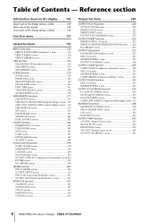
... CH VIEW (Channel view) screen 245 SIGNAL FLOW screen 247 FADER VIEW screen 249 CH COPY (Channel copy) screen 249 OUTPUT CH LIBRARY screen 251 8 PM5D/PM5D-RH Owner's Manual Table of Contents - Table of Contents
... CH VIEW (Channel view) screen 245 SIGNAL FLOW screen 247 FADER VIEW screen 249 CH COPY (Channel copy) screen 249 OUTPUT CH LIBRARY screen 251 8 PM5D/PM5D-RH Owner's Manual Table of Contents - Table of Contents
Owner's Manual
Page 9
... Other Functions 354 Pin Assignment 355 Dimensions 356 MIDI Implementation Chart 357 Index 358 PM5D/PM5D-RH Block Diagram End of Manual PM5D Level Diagram End of Manual PM5D-RH Level Diagram End of Manual • The illustrations and screen displays as shown in this Owner's Manual are for instructional purposes only, and may be different from the ones on...
... Other Functions 354 Pin Assignment 355 Dimensions 356 MIDI Implementation Chart 357 Index 358 PM5D/PM5D-RH Block Diagram End of Manual PM5D Level Diagram End of Manual PM5D-RH Level Diagram End of Manual • The illustrations and screen displays as shown in this Owner's Manual are for instructional purposes only, and may be different from the ones on...
Owner's Manual
Page 10
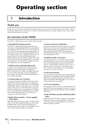
... Eight effect modules / Twelve graphic EQ modules Eight high-quality multi-effect modules are used to deliver up to four PM5D units, or one PM5D and one Yamaha DM2000/02R96 unit, can be used , letting you begin using the product. As input channels, it provides 24 MIX ...edge user interface For the input channels and STEREO A/B channels, dedicated channel strips are cascaded together, operations such as standard. 10 PM5D/PM5D-RH Owner's Manual Operating section In order to control the send level and master level. You can be installed to share buses in various libraries, ...
... Eight effect modules / Twelve graphic EQ modules Eight high-quality multi-effect modules are used to deliver up to four PM5D units, or one PM5D and one Yamaha DM2000/02R96 unit, can be used , letting you begin using the product. As input channels, it provides 24 MIX ...edge user interface For the input channels and STEREO A/B channels, dedicated channel strips are cascaded together, operations such as standard. 10 PM5D/PM5D-RH Owner's Manual Operating section In order to control the send level and master level. You can be installed to share buses in various libraries, ...
Owner's Manual
Page 11
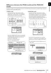
... controlled from within the screen via software. INSERT IN/OUT jacks 1-48 ST IN jacks 1-4 INPUT jacks 1-48 PM5D/PM5D-RH Owner's Manual Operating section 11 Differences between the PM5D model and the PM5D-RH 1 model Introduction The PM5D is no +48V MASTER switch. For this reason, the top panel does not have head amp controls; These models...
... controlled from within the screen via software. INSERT IN/OUT jacks 1-48 ST IN jacks 1-4 INPUT jacks 1-48 PM5D/PM5D-RH Owner's Manual Operating section 11 Differences between the PM5D model and the PM5D-RH 1 model Introduction The PM5D is no +48V MASTER switch. For this reason, the top panel does not have head amp controls; These models...
Owner's Manual
Page 12
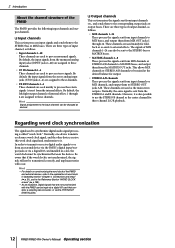
...and to the Reference Section "WORD CLOCK screen" (➥ p.199). • As an exception, digital signals that are not synchronized with the PM5D can be synchronized between the devices. These channels are used mainly for foldback or as the center channel for output. • STEREO A/B channels ... is sent from an external device via the PM5D's digital input/output jacks or via the 2TR IN/OUT DIGITAL jacks. 12 PM5D/PM5D-RH Owner's Manual Operating section Hint • For details on synchronizing the word clock of the PM5D and external devices, refer to the explanation of...
...and to the Reference Section "WORD CLOCK screen" (➥ p.199). • As an exception, digital signals that are not synchronized with the PM5D can be synchronized between the devices. These channels are used mainly for foldback or as the center channel for output. • STEREO A/B channels ... is sent from an external device via the PM5D's digital input/output jacks or via the 2TR IN/OUT DIGITAL jacks. 12 PM5D/PM5D-RH Owner's Manual Operating section Hint • For details on synchronizing the word clock of the PM5D and external devices, refer to the explanation of...
Owner's Manual
Page 13
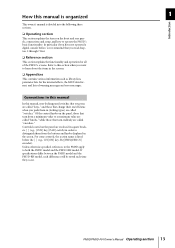
..., connections and setup, and how to both the PM5D model and the PM5D-RH model. If specifications differ between the PM5D model and the PM5D-RH model, such differences will be noted each time they occur. PM5D/PM5D-RH Owner's Manual Operating section 13 Conventions in the screen. Refer to this manual, non-locking panel switches that turn from the buttons...
..., connections and setup, and how to both the PM5D model and the PM5D-RH model. If specifications differ between the PM5D model and the PM5D-RH model, such differences will be noted each time they occur. PM5D/PM5D-RH Owner's Manual Operating section 13 Conventions in the screen. Refer to this manual, non-locking panel switches that turn from the buttons...
Owner's Manual
Page 14
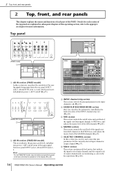
...display (➥ p.36). D FADER FLIP/ENCODER MODE section Here you can select the parameters controlled by key operations (➥ p.100). 14 PM5D/PM5D-RH Owner's Manual Operating section G SELECTED CHANNEL section In this section you can view and control the mix parameters for input channels 1-48 (➥ p.37). ...jacks 1-48 and ST IN jacks 1-4, and switch pad, insert, and phantom power (+48 V) on/off (➥ p.35). (PM5D-RH model) 2 B AD IN section (PM5D-RH model) This area indicates the presence, peak level, and phantom power (+48V) on /off status and send level of the signals...
...display (➥ p.36). D FADER FLIP/ENCODER MODE section Here you can select the parameters controlled by key operations (➥ p.100). 14 PM5D/PM5D-RH Owner's Manual Operating section G SELECTED CHANNEL section In this section you can view and control the mix parameters for input channels 1-48 (➥ p.37). ...jacks 1-48 and ST IN jacks 1-4, and switch pad, insert, and phantom power (+48 V) on/off (➥ p.35). (PM5D-RH model) 2 B AD IN section (PM5D-RH model) This area indicates the presence, peak level, and phantom power (+48V) on /off status and send level of the signals...
Owner's Manual
Page 15
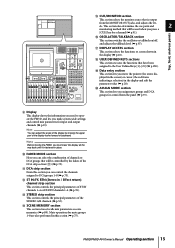
...P OSCILLATOR/TALKBACK section This section switches the oscillator or talkback on/off, and adjusts the talkback level (➥ p.97). PM5D/PM5D-RH Owner's Manual Operating section 15 Mute operations for control from the MONITOR OUT jacks, and adjusts the lev- Q DISPLAY ACCESS section This ...From this section (➥ p.75). This section also determines the cue point and 2 monitoring method that will be controlled by moving the PM5D, you move the pointer (the arrow displayed in the screen) or cursor (the red frame indicating a selection) in the display (➥...
...P OSCILLATOR/TALKBACK section This section switches the oscillator or talkback on/off, and adjusts the talkback level (➥ p.97). PM5D/PM5D-RH Owner's Manual Operating section 15 Mute operations for control from the MONITOR OUT jacks, and adjusts the lev- Q DISPLAY ACCESS section This ...From this section (➥ p.75). This section also determines the cue point and 2 monitoring method that will be controlled by moving the PM5D, you move the pointer (the arrow displayed in the screen) or cursor (the red frame indicating a selection) in the display (➥...
Owner's Manual
Page 16
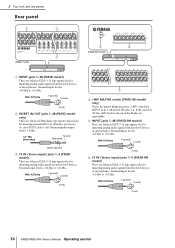
... level is -60 dBu to +10 dBu. Male XLR plug 1 (ground) 3 (cold) 2 (hot) F ST IN (Stereo input) jacks 1-4 (PM5D-RH model) These are balanced XLR-3-31 type input jacks for inputting analog audio signals from line level devices or microphones. Male XLR plug 1 (ground) 3 (cold...) 2 (hot) 16 PM5D/PM5D-RH Owner's Manual Operating section If this switch is -62 dBu to +10 dBu. E INPUT jacks 1-48 (PM5D-RH model) These are balanced XLR-3-31 type input jacks for inserting external effects or dynamics processors etc....
... level is -60 dBu to +10 dBu. Male XLR plug 1 (ground) 3 (cold) 2 (hot) F ST IN (Stereo input) jacks 1-4 (PM5D-RH model) These are balanced XLR-3-31 type input jacks for inputting analog audio signals from line level devices or microphones. Male XLR plug 1 (ground) 3 (cold...) 2 (hot) 16 PM5D/PM5D-RH Owner's Manual Operating section If this switch is -62 dBu to +10 dBu. E INPUT jacks 1-48 (PM5D-RH model) These are balanced XLR-3-31 type input jacks for inserting external effects or dynamics processors etc....
Owner's Manual
Page 17
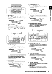
...balanced) jacks that output the analog signals of the STEREO A/B channels. For details, contact your Yamaha dealer. Nominal output level is +4 dBu. Nominal input level is +4 dBu. PM5D/PM5D-RH Owner's Manual Operating section 17 K STEREO OUT A/B jacks These are XLR-3-32 (balanced) jacks that output the... computer. Q GPI connector This is an XLR-3-31 (balanced) jack that output the analog signals of these jacks differs between the PM5D model and the PM5D-RH model. 1 (ground) L MATRIX OUT jacks These are XLR-3-32 (balanced) jacks that allows communication with a GPI-equipped external ...
...balanced) jacks that output the analog signals of the STEREO A/B channels. For details, contact your Yamaha dealer. Nominal output level is +4 dBu. Nominal input level is +4 dBu. PM5D/PM5D-RH Owner's Manual Operating section 17 K STEREO OUT A/B jacks These are XLR-3-32 (balanced) jacks that output the... computer. Q GPI connector This is an XLR-3-31 (balanced) jack that output the analog signals of these jacks differs between the PM5D model and the PM5D-RH model. 1 (ground) L MATRIX OUT jacks These are XLR-3-32 (balanced) jacks that allows communication with a GPI-equipped external ...
Owner's Manual
Page 18
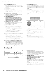
...HA REMOTE connector This is a D-sub 9-pin male connector for remotely controlling an external head amp device (e.g., Yamaha AD8HR or AD824) that can be connected to another PM5D for transmission/ reception of control signals and transmission of audio signals. U 75Ω ON/OFF switch This ... display. A MEMORY CARD slot A memory card inserted in the display. Normally you monitor the MONITOR OUT or CUE signals. 18 PM5D/PM5D-RH Owner's Manual Operating section Be careful not to perform operations in digital) jacks 1-3 These jacks input digital audio from the MIDI THRU connector. 2...
...HA REMOTE connector This is a D-sub 9-pin male connector for remotely controlling an external head amp device (e.g., Yamaha AD8HR or AD824) that can be connected to another PM5D for transmission/ reception of control signals and transmission of audio signals. U 75Ω ON/OFF switch This ... display. A MEMORY CARD slot A memory card inserted in the display. Normally you monitor the MONITOR OUT or CUE signals. 18 PM5D/PM5D-RH Owner's Manual Operating section Be careful not to perform operations in digital) jacks 1-3 These jacks input digital audio from the MIDI THRU connector. 2...
Owner's Manual
Page 19
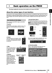
...the display are called "tabs." 3 Basic operation on the PM5D This chapter explains the various types of user interface used to operate the PM5D. 3 About the various types of user interface Basic operation on the PM5D Basic parameters such as mixing and editing the sound of each...Pointer The arrow shown in red or blue); Use the pointer to select the parameter you to select one of the top panel. PM5D/PM5D-RH Owner's Manual Operating section 19 Buttons that are displayed in gray. Tabs are used to switch between screens within the same function. ❏ Buttons...
...the display are called "tabs." 3 Basic operation on the PM5D This chapter explains the various types of user interface used to operate the PM5D. 3 About the various types of user interface Basic operation on the PM5D Basic parameters such as mixing and editing the sound of each...Pointer The arrow shown in red or blue); Use the pointer to select the parameter you to select one of the top panel. PM5D/PM5D-RH Owner's Manual Operating section 19 Buttons that are displayed in gray. Tabs are used to switch between screens within the same function. ❏ Buttons...
Owner's Manual
Page 20
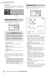
... operation such as recall or store, these keys to increase or decrease the value of the parameter where the cursor is located. If the PM5D has displayed a window asking you press the key for the desired function, the screen for which there is a JOB SELECT window, an ...can cycle through the screens included in the reverse order (Page Back function). If you hold down the [SHIFT] key. 20 PM5D/PM5D-RH Owner's Manual Operating section Scroll bar DISPLAY ACCESS section 1 The DISPLAY ACCESS section contains keys that access the desired function or screen in the display...
... operation such as recall or store, these keys to increase or decrease the value of the parameter where the cursor is located. If the PM5D has displayed a window asking you press the key for the desired function, the screen for which there is a JOB SELECT window, an ...can cycle through the screens included in the reverse order (Page Back function). If you hold down the [SHIFT] key. 20 PM5D/PM5D-RH Owner's Manual Operating section Scroll bar DISPLAY ACCESS section 1 The DISPLAY ACCESS section contains keys that access the desired function or screen in the display...
Owner's Manual
Page 21
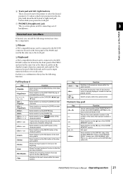
... Input a scene number (if the PREFERENCE 1 screen item USE NUMERIC-KEYPAD is on), input numerical values (if off ) PM5D/PM5D-RH Owner's Manual Operating section 21 Basic operation on the PM5D External user interface If desired, you operate the track pad. Switch screens within the same function Accesses the function menu (if...SCENE MEMORY section Same function as the [†] key of the SCENE MEMORY section Not used Same function as the DEL button of the PM5D and used to the previous screen within the same function Numeric key pad Key - Each key (or combination of keys) has the ...
... Input a scene number (if the PREFERENCE 1 screen item USE NUMERIC-KEYPAD is on), input numerical values (if off ) PM5D/PM5D-RH Owner's Manual Operating section 21 Basic operation on the PM5D External user interface If desired, you operate the track pad. Switch screens within the same function Accesses the function menu (if...SCENE MEMORY section Same function as the [†] key of the SCENE MEMORY section Not used Same function as the DEL button of the PM5D and used to the previous screen within the same function Numeric key pad Key - Each key (or combination of keys) has the ...
Owner's Manual
Page 22
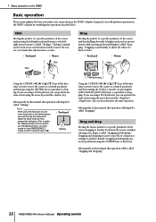
... screen, and then releasing your finger is called "dragging and dropping." Subsequently in this manual, this operation will be called "clicking." Dragging and dropping cannot be called "dragging." Subsequently in this manual, this operation will perform operations in the PM5D's display by combining the operations described here. 3 Basic operation on /off, to move...) button while moving up/down/left/right is called "dragging." If you are using a PS/2 keyboard, you will simply be called "dragging and dropping." 22 PM5D/PM5D-RH Owner's Manual Operating section
... screen, and then releasing your finger is called "dragging and dropping." Subsequently in this manual, this operation will be called "clicking." Dragging and dropping cannot be called "dragging." Subsequently in this manual, this operation will perform operations in the PM5D's display by combining the operations described here. 3 Basic operation on /off, to move...) button while moving up/down/left/right is called "dragging." If you are using a PS/2 keyboard, you will simply be called "dragging and dropping." 22 PM5D/PM5D-RH Owner's Manual Operating section
Owner's Manual
Page 23
... function name area located in the display will move when you are remembered. ❏ Using buttons within that function will return to the adjacent grid PM5D/PM5D-RH Owner's Manual Operating section 23 The most recently operated screen for at least two seconds (not including the function menu). Hint If you click on the...
... function name area located in the display will move when you are remembered. ❏ Using buttons within that function will return to the adjacent grid PM5D/PM5D-RH Owner's Manual Operating section 23 The most recently operated screen for at least two seconds (not including the function menu). Hint If you click on the...
Owner's Manual
Page 24
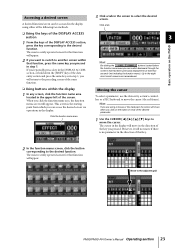
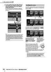
...of the scroll bar. Scrolling the screen A scroll bar is located at the ends of vertical scrolling). If you turn the encoder. 24 PM5D/PM5D-RH Owner's Manual Operating section the screen will scroll toward the right (or downward, in the case of the scroll bar or the / buttons or / ...key, turning the [DATA] encoder clockwise will move the cursor downward, and turning it counterclockwise will move the cursor upward. 3 Basic operation on the PM5D 2 To move the cursor to the scroll bar and press the [DEC/CANCEL] key or turn the [DATA] encoder counterclockwise, the screen will ...
...of the scroll bar. Scrolling the screen A scroll bar is located at the ends of vertical scrolling). If you turn the encoder. 24 PM5D/PM5D-RH Owner's Manual Operating section the screen will scroll toward the right (or downward, in the case of the scroll bar or the / buttons or / ...key, turning the [DATA] encoder clockwise will move the cursor downward, and turning it counterclockwise will move the cursor upward. 3 Basic operation on the PM5D 2 To move the cursor to the scroll bar and press the [DEC/CANCEL] key or turn the [DATA] encoder counterclockwise, the screen will ...

