

Owner's Manual
Page 2
...radio or TV interference, relocate/reorient the antenna. Failure to follow instructions could void your FCC authorization to those products distributed by Yamaha Corporation of product. If this product to accessories and/ or another product use attachments/accessories specified by the manufacturer. 12... plug has two blades with one of the following measures: Relocate either this product or the device that interference will not result in the users manual, may void your safety. A grounding type plug has two blades and a third grounding prong. The wide blade or the third prong ...
...radio or TV interference, relocate/reorient the antenna. Failure to follow instructions could void your FCC authorization to those products distributed by Yamaha Corporation of product. If this product to accessories and/ or another product use attachments/accessories specified by the manufacturer. 12... plug has two blades with one of the following measures: Relocate either this product or the device that interference will not result in the users manual, may void your safety. A grounding type plug has two blades and a third grounding prong. The wide blade or the third prong ...
Owner's Manual
Page 4
... not to , the following : Power supply/Power cord • Use only the specified power supply (PW800W or an equivalent recommended by Yamaha). • Only use of the connected devices, doing so may cause feedback and may generate noise. (5)-1 1/2 Pulling by the cord can cause ...disconnect the electric plug from the outlet, and have the device inspected by qualified Yamaha service personnel. • If this manual in a safe place for future reference. The device contains no user-serviceable parts. Water warning • Do not expose the device to avoid the possibility of ...
... not to , the following : Power supply/Power cord • Use only the specified power supply (PW800W or an equivalent recommended by Yamaha). • Only use of the connected devices, doing so may cause feedback and may generate noise. (5)-1 1/2 Pulling by the cord can cause ...disconnect the electric plug from the outlet, and have the device inspected by qualified Yamaha service personnel. • If this manual in a safe place for future reference. The device contains no user-serviceable parts. Water warning • Do not expose the device to avoid the possibility of ...
Owner's Manual
Page 6
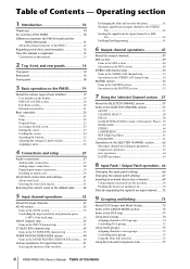
...Regarding word clock synchronization 12 How this manual is organized 13 Conventions in this manual 13 2 Top, front, and rear panels 14 Top panel 14 Rear panel 16 Front panel 18 3 Basic operation on the PM5D 19 About the various types of user interface 19 User interface in the display 19 DISPLAY ...ACCESS section 20 Data Entry section 20 External user interface 21 ...
...Regarding word clock synchronization 12 How this manual is organized 13 Conventions in this manual 13 2 Top, front, and rear panels 14 Top panel 14 Rear panel 16 Front panel 18 3 Basic operation on the PM5D 19 About the various types of user interface 19 User interface in the display 19 DISPLAY ...ACCESS section 20 Data Entry section 20 External user interface 21 ...
Owner's Manual
Page 7
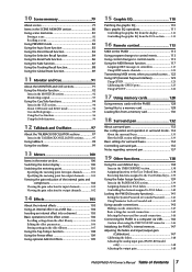
...Notes regarding surround pan 137 19 Other functions 138 Using the user defined keys 138 Items in the USER DEFINED section 138 Assigning functions to the User Defined keys 138 Executing functions assigned to the User Defined keys... 139 Using the Fader Assign function 139 Items ...using the USB TO HOST connector ........ 146 Initializing the PM5D's internal memory 147 Adjusting the faders and input/output gain (Calibration 147 Calibrating the faders 148 Adjusting the analog input gain (PM5D-RH model only 148 Adjusting the output gain 148 PM5D/PM5D-RH Owner's Manual Table of Contents 7
...Notes regarding surround pan 137 19 Other functions 138 Using the user defined keys 138 Items in the USER DEFINED section 138 Assigning functions to the User Defined keys 138 Executing functions assigned to the User Defined keys... 139 Using the Fader Assign function 139 Items ...using the USB TO HOST connector ........ 146 Initializing the PM5D's internal memory 147 Adjusting the faders and input/output gain (Calibration 147 Calibrating the faders 148 Adjusting the analog input gain (PM5D-RH model only 148 Adjusting the output gain 148 PM5D/PM5D-RH Owner's Manual Table of Contents 7
Owner's Manual
Page 8
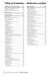
... ... 174 MIDI REMOTE screen 175 GPI screen 177 FADER START screen 179 TRANSPORT screen 181 DME CONTROL screen 182 UTILITY function 186 PREFERENCE 1/2 screens 186 USER DEFINE screen 189 SAVE screen 192 LOAD screen 195 FADER ASSIGN screen 197 SECURITY screen 198 SYS/W.CLOCK function 199 WORD CLOCK screen 199 MIXER... CH VIEW (Channel view) screen 245 SIGNAL FLOW screen 247 FADER VIEW screen 249 CH COPY (Channel copy) screen 249 OUTPUT CH LIBRARY screen 251 8 PM5D/PM5D-RH Owner's Manual Table of Contents - Table of Contents
... ... 174 MIDI REMOTE screen 175 GPI screen 177 FADER START screen 179 TRANSPORT screen 181 DME CONTROL screen 182 UTILITY function 186 PREFERENCE 1/2 screens 186 USER DEFINE screen 189 SAVE screen 192 LOAD screen 195 FADER ASSIGN screen 197 SECURITY screen 198 SYS/W.CLOCK function 199 WORD CLOCK screen 199 MIXER... CH VIEW (Channel view) screen 245 SIGNAL FLOW screen 247 FADER VIEW screen 249 CH COPY (Channel copy) screen 249 OUTPUT CH LIBRARY screen 251 8 PM5D/PM5D-RH Owner's Manual Table of Contents - Table of Contents
Owner's Manual
Page 10
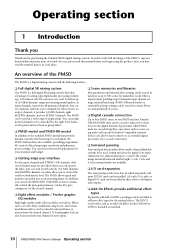
...independently of scenes. ❏ Digital cascade connection Up to four PM5D units, or one PM5D and one Yamaha DM2000/02R96 unit, can be controlled by the eight DCA faders on the panel, and use the SELECTED CHANNEL section to manually control the principal parameters (delay, EQ, gate, compressor) of...slots to control the send level and master level. You can choose the model appropriate for your situation and budget. ❏ Cutting-edge user interface For the input channels and STEREO A/B channels, dedicated channel strips are cascaded together, operations such as on an analog mixer. As...
...independently of scenes. ❏ Digital cascade connection Up to four PM5D units, or one PM5D and one Yamaha DM2000/02R96 unit, can be controlled by the eight DCA faders on the panel, and use the SELECTED CHANNEL section to manually control the principal parameters (delay, EQ, gate, compressor) of...slots to control the send level and master level. You can choose the model appropriate for your situation and budget. ❏ Cutting-edge user interface For the input channels and STEREO A/B channels, dedicated channel strips are cascaded together, operations such as on an analog mixer. As...
Owner's Manual
Page 15
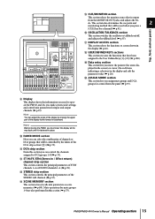
...fastened in place. This section also determines the cue point and 2 monitoring method that have been assigned to DCA groups 1-8 (➥ p.73). R USER DEFINED KEYS sections This section executes the functions that will be used when you can control the channels assigned to the...T ASSIGN MODE section This section lets you can adjust the angle of the display by the faders of the STEREO A/B channels (➥ p.53). PM5D/PM5D-RH Owner's Manual Operating section 15 S Data entry section This section lets you must lower the display all the way back until it is output from the...
...fastened in place. This section also determines the cue point and 2 monitoring method that have been assigned to DCA groups 1-8 (➥ p.73). R USER DEFINED KEYS sections This section executes the functions that will be used when you can control the channels assigned to the...T ASSIGN MODE section This section lets you can adjust the angle of the display by the faders of the STEREO A/B channels (➥ p.53). PM5D/PM5D-RH Owner's Manual Operating section 15 S Data entry section This section lets you must lower the display all the way back until it is output from the...
Owner's Manual
Page 19
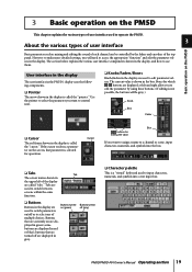
...is a "virtual" keyboard used to edit the parameter by the faders and encoders of the top panel. PM5D/PM5D-RH Owner's Manual Operating section 19 The section below explains the various user interface components shown in the display, and how to access the appropriate "function" and edit the parameter ...red frame shown in the display. Use the pointer to select the parameter you want to assign a name to operate the PM5D. 3 About the various types of user interface Basic operation on /off or to edit parameter values. The current value is called the "pointer." Boxes for operation....
...is a "virtual" keyboard used to edit the parameter by the faders and encoders of the top panel. PM5D/PM5D-RH Owner's Manual Operating section 19 The section below explains the various user interface components shown in the display, and how to access the appropriate "function" and edit the parameter ...red frame shown in the display. Use the pointer to select the parameter you want to assign a name to operate the PM5D. 3 About the various types of user interface Basic operation on /off or to edit parameter values. The current value is called the "pointer." Boxes for operation....
Owner's Manual
Page 21
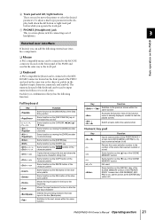
...connecting a set of the keyboard can be used to the KEYBOARD connector located on ), input numerical values (if off ) PM5D/PM5D-RH Owner's Manual Operating section 21 Function Input a scene number (if the PREFERENCE 1 screen item USE NUMERIC-KEYPAD is on the front panel ... the function menu (if the function menu is already displayed, recalls the last-displayed screen) + - G PHONES (Headphone) jack This is on the PM5D External user interface If desired, you operate the track pad. Full keyboard Key + + + , + + + + Function Same function as the [INS/OK]...
...connecting a set of the keyboard can be used to the KEYBOARD connector located on ), input numerical values (if off ) PM5D/PM5D-RH Owner's Manual Operating section 21 Function Input a scene number (if the PREFERENCE 1 screen item USE NUMERIC-KEYPAD is on the front panel ... the function menu (if the function menu is already displayed, recalls the last-displayed screen) + - G PHONES (Headphone) jack This is on the PM5D External user interface If desired, you operate the track pad. Full keyboard Key + + + , + + + + Function Same function as the [INS/OK]...
Owner's Manual
Page 82
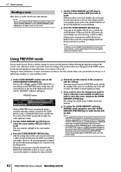
...specific screen in the display to examine the values in step 4 will be loaded and shown in the USER DEFINED screen will turn it was prior to the current scene. 82 PM5D/PM5D-RH Owner's Manual Operating section The settings you made in step 4, select the scene number in the scene number indicator of...number and name shown at the top of the SCENE MEMORY section will appear. A message in PREVIEW mode. Only the setting values of the PM5D model) will ask you can be recalled. The key LED will light, and the SCENE MEMORY section will operate in the display will not affect...
...specific screen in the display to examine the values in step 4 will be loaded and shown in the USER DEFINED screen will turn it was prior to the current scene. 82 PM5D/PM5D-RH Owner's Manual Operating section The settings you made in step 4, select the scene number in the scene number indicator of...number and name shown at the top of the SCENE MEMORY section will appear. A message in PREVIEW mode. Only the setting values of the PM5D model) will ask you can be recalled. The key LED will light, and the SCENE MEMORY section will operate in the display will not affect...

Owner's Manual
Page 98
... talkback dimmer to lower the monitor levels other than talkback (➥ p.216). • You can also assign the talkback function to a user-defined key (➥ p.189). 98 PM5D/PM5D-RH Owner's Manual Operating section Hint • The TALKBACK [ON] key of the talkback mic. To do so, click the PATCH button in the TALKBACK...
... talkback dimmer to lower the monitor levels other than talkback (➥ p.216). • You can also assign the talkback function to a user-defined key (➥ p.189). 98 PM5D/PM5D-RH Owner's Manual Operating section Hint • The TALKBACK [ON] key of the talkback mic. To do so, click the PATCH button in the TALKBACK...
Owner's Manual
Page 124
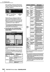
... pressed USER DEFINED KEY LED [User Defined While the external input is grounded; In this case, we recommend that you can select the PM5D function that will be adjusted to suit the external controller (except for your situation. 124 PM5D/PM5D-RH Owner's Manual Operating... section No assignment DIMMER ON Switches the Dimmer function on/off MONITOR SOURCE = [monitor source name] Switches the monitor source MONO ON Switches the Monitor section [MONO] key on FUNCTION PARAMETER PM5D operation TALKBACK ON LATCH...
... pressed USER DEFINED KEY LED [User Defined While the external input is grounded; In this case, we recommend that you can select the PM5D function that will be adjusted to suit the external controller (except for your situation. 124 PM5D/PM5D-RH Owner's Manual Operating... section No assignment DIMMER ON Switches the Dimmer function on/off MONITOR SOURCE = [monitor source name] Switches the monitor source MONO ON Switches the Monitor section [MONO] key on FUNCTION PARAMETER PM5D operation TALKBACK ON LATCH...
Owner's Manual
Page 126
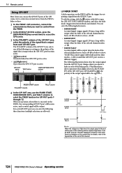
You can select the following illustration shows how the output signal from the GPI OUT port changes when you operate a fader in this manual. 126 PM5D/PM5D-RH Owner's Manual Operating section The following fader modes. • FADER START A control signal (trigger signal) 250 msec long will be output when the ...as the POLARITY of the signal that GPI OUT port receives a different trigger). For each GPI OUT port. GPI OUT status TEST button USER DEFINED KEYS column FADER START column POLARITY column TALLY column 4 In the GPI OUT area, use the GPI OUT ports of the GPI connector...
You can select the following illustration shows how the output signal from the GPI OUT port changes when you operate a fader in this manual. 126 PM5D/PM5D-RH Owner's Manual Operating section The following fader modes. • FADER START A control signal (trigger signal) 250 msec long will be output when the ...as the POLARITY of the signal that GPI OUT port receives a different trigger). For each GPI OUT port. GPI OUT status TEST button USER DEFINED KEYS column FADER START column POLARITY column TALLY column 4 In the GPI OUT area, use the GPI OUT ports of the GPI connector...
Owner's Manual
Page 127
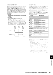
... when you defeat the above operation (or until you operate a User Defined key in the same way. When the corresponding operation is ...Active only while the key remains pressed. from the list, select the User Defined key bank (A-D) and number (1-25), and choose the trigger mode ...functions. Function PM5D operation NO ASSIGN No assignment POWER ON The PM5D's power is turned on SOLO ON [SOLO] key is on the PM5D, a control.... The background color is pressed). ❏ USER DEFINED KEYS Operation of a User Defined key on the PM5D will be the trigger for outputting a signal ...
... when you defeat the above operation (or until you operate a User Defined key in the same way. When the corresponding operation is ...Active only while the key remains pressed. from the list, select the User Defined key bank (A-D) and number (1-25), and choose the trigger mode ...functions. Function PM5D operation NO ASSIGN No assignment POWER ON The PM5D's power is turned on SOLO ON [SOLO] key is on the PM5D, a control.... The background color is pressed). ❏ USER DEFINED KEYS Operation of a User Defined key on the PM5D will be the trigger for outputting a signal ...
Owner's Manual
Page 129
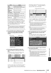
... right of the button to specify the starting number and ending number so that will save destination is shown below the file list. PM5D/PM5D-RH Owner's Manual Operating section 129 Hint The TOTAL SIZE field at the bottom of the MODE area indicates the file size for saving, use the ... scenes or libraries for the selected item(s). Button Content GEQ Contents of the GEQ library SETUP Various settings not saved in a scene USER DEFINED KEY User Defined key settings DCA FADER MODE DCA fader mode settings MIDI REMOTE MIDI remote settings MIDI PGM TABLE Contents of the list...
... right of the button to specify the starting number and ending number so that will save destination is shown below the file list. PM5D/PM5D-RH Owner's Manual Operating section 129 Hint The TOTAL SIZE field at the bottom of the MODE area indicates the file size for saving, use the ... scenes or libraries for the selected item(s). Button Content GEQ Contents of the GEQ library SETUP Various settings not saved in a scene USER DEFINED KEY User Defined key settings DCA FADER MODE DCA fader mode settings MIDI REMOTE MIDI remote settings MIDI PGM TABLE Contents of the list...
Owner's Manual
Page 138
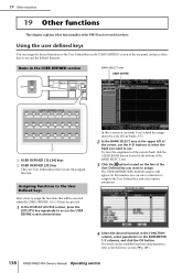
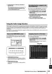
...the available functions and parameters, refer to the Reference section (➥ p.189). 138 PM5D/PM5D-RH Owner's Manual Operating section Items in the USER DEFINED section BANK SELECT area USER DEFINE 2 1 A USER DEFINED [1]-[24] keys B USER DEFINED [25] key These are pressed. 1 In the DISPLAY ACCESS section, press...option parameters. 4 Select the desired function in the FUNCTION column, select parameters in the USER DEFINED section of the PM5D not covered elsewhere. Assigning functions to the User Defined keys Here's how to assign the functions that will appear. 19 Other...
...the available functions and parameters, refer to the Reference section (➥ p.189). 138 PM5D/PM5D-RH Owner's Manual Operating section Items in the USER DEFINED section BANK SELECT area USER DEFINE 2 1 A USER DEFINED [1]-[24] keys B USER DEFINED [25] key These are pressed. 1 In the DISPLAY ACCESS section, press...option parameters. 4 Select the desired function in the FUNCTION column, select parameters in the USER DEFINED section of the PM5D not covered elsewhere. Assigning functions to the User Defined keys Here's how to assign the functions that will appear. 19 Other...
Owner's Manual
Page 139
... to simultaneously control the send level and return level of an internal effect, or to use a fader as USER DEFINED KEY data. For each fader in the top panel. Other functions 19 PM5D/PM5D-RH Owner's Manual Operating section 139 For example, you operate the faders. F). Assigning channels to DCA faders Here's how to...
... to simultaneously control the send level and return level of an internal effect, or to use a fader as USER DEFINED KEY data. For each fader in the top panel. Other functions 19 PM5D/PM5D-RH Owner's Manual Operating section 139 For example, you operate the faders. F). Assigning channels to DCA faders Here's how to...
Owner's Manual
Page 149
...storing it, the EDIT indicator in the EVENT LIST screen.) • If a time is displayed, this function name indication. Input functions Appendices PM5D/PM5D-RH Owner's Manual Reference section 149 At the right is displayed the time until the next event is recalled automatically. • The "--------" indication means that will be...NEXT EVENT Indicates the scene/event that there is no event to be recalled when you can also access the Function menu by the User Defined keys or the Event List function. You can move the cursor to the scene number and turn the [DATA] encoder to ...
...storing it, the EDIT indicator in the EVENT LIST screen.) • If a time is displayed, this function name indication. Input functions Appendices PM5D/PM5D-RH Owner's Manual Reference section 149 At the right is displayed the time until the next event is recalled automatically. • The "--------" indication means that will be...NEXT EVENT Indicates the scene/event that there is no event to be recalled when you can also access the Function menu by the User Defined keys or the Event List function. You can move the cursor to the scene number and turn the [DATA] encoder to ...
Owner's Manual
Page 151
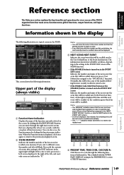
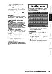
... for the faders; You can also be assigned to input channels (input channels, ST IN channels, FX RTN channels). H USER DEFINED KEY BANK Indicates the currently selected bank of the display. Function menu Here you want to view in the display. Information... can also click the / buttons to output channels (MIX channels, MATRIX channels, STEREO A/B channels). Output functions Input functions Appendices PM5D/PM5D-RH Owner's Manual Reference section 151 C Input-related functions These buttons access functions related to the encoders. the LEVEL parameter will switch mute groups 1-8...
... for the faders; You can also be assigned to input channels (input channels, ST IN channels, FX RTN channels). H USER DEFINED KEY BANK Indicates the currently selected bank of the display. Function menu Here you want to view in the display. Information... can also click the / buttons to output channels (MIX channels, MATRIX channels, STEREO A/B channels). Output functions Input functions Appendices PM5D/PM5D-RH Owner's Manual Reference section 151 C Input-related functions These buttons access functions related to the encoders. the LEVEL parameter will switch mute groups 1-8...
Owner's Manual
Page 160
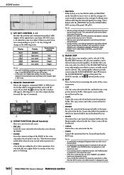
...again (Redo) to return to the state prior to internal signal processing even during Preview. • During Preview, user defined operations that affect internal signal processing are displayed in gray. • If you switch scenes using the SCENE ...let you inserted will be performed during Preview mode. In contrast if the BLANK SKIP button is on , the PM5D will be transmitted when you can store/recall scenes. • RECALL Loads the scene currently selected in the ...is selected in the list, the PASTE button is displayed in gray. 160 PM5D/PM5D-RH Owner's Manual Reference section
...again (Redo) to return to the state prior to internal signal processing even during Preview. • During Preview, user defined operations that affect internal signal processing are displayed in gray. • If you switch scenes using the SCENE ...let you inserted will be performed during Preview mode. In contrast if the BLANK SKIP button is on , the PM5D will be transmitted when you can store/recall scenes. • RECALL Loads the scene currently selected in the ...is selected in the list, the PASTE button is displayed in gray. 160 PM5D/PM5D-RH Owner's Manual Reference section


