
Owner's Manual
Page 4
..., discontinue use four or more people. • Before moving the device, always use immediately and have the device inspected by qualified Yamaha service personnel. These precautions include, but are not limited to, the following : Power supply/Power cord • Use only the specifi...if any way. Location • When transporting or moving the device, remove all connected cables. • Avoid setting all equalizer controls and faders to avoid the possibility of serious injury or even death from the outlet when the device is printed on it , immediately turn off the...
..., discontinue use four or more people. • Before moving the device, always use immediately and have the device inspected by qualified Yamaha service personnel. These precautions include, but are not limited to, the following : Power supply/Power cord • Use only the specifi...if any way. Location • When transporting or moving the device, remove all connected cables. • Avoid setting all equalizer controls and faders to avoid the possibility of serious injury or even death from the outlet when the device is printed on it , immediately turn off the...
Owner's Manual
Page 6
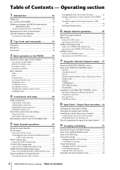
...in this manual 13 2 Top, front, and rear panels 14 Top panel 14 Rear panel 16 Front panel 18 3 Basic operation on the PM5D 19 About the various types of user interface 19 User interface in the display 19 DISPLAY ACCESS section 20 Data Entry section 20 External user... drop 22 Accessing a desired screen 23 Moving the cursor 23 Scrolling the screen 24 Operating the buttons 25 Adjusting the setting of a knob or fader 25 Assigning a name 26 4 Connections and setup 27 Audio connections 27 Analog audio connections 27 Analog output connections 28 Digital input/output connections 29...
...in this manual 13 2 Top, front, and rear panels 14 Top panel 14 Rear panel 16 Front panel 18 3 Basic operation on the PM5D 19 About the various types of user interface 19 User interface in the display 19 DISPLAY ACCESS section 20 Data Entry section 20 External user... drop 22 Accessing a desired screen 23 Moving the cursor 23 Scrolling the screen 24 Operating the buttons 25 Adjusting the setting of a knob or fader 25 Assigning a name 26 4 Connections and setup 27 Audio connections 27 Analog audio connections 27 Analog output connections 28 Digital input/output connections 29...
Owner's Manual
Page 7
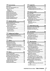
... Defined keys 138 Executing functions assigned to the User Defined keys... 139 Using the Fader Assign function 139 Items in the FADER MODE section 139 Assigning channels to DCA faders 139 Controlling the channels assigned to DCA faders 140 Locking the PM5D (Security functions 141 Setting the System Password or Console Password.......... 141 Using Parameter...
... Defined keys 138 Executing functions assigned to the User Defined keys... 139 Using the Fader Assign function 139 Items in the FADER MODE section 139 Assigning channels to DCA faders 139 Controlling the channels assigned to DCA faders 140 Locking the PM5D (Security functions 141 Setting the System Password or Console Password.......... 141 Using Parameter...
Owner's Manual
Page 8
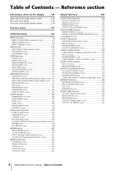
...PGM CHANGE (MIDI program change) screen .. 173 MIDI CTRL CHANGE (MIDI control change) screen ... 174 MIDI REMOTE screen 175 GPI screen 177 FADER START screen 179 TRANSPORT screen 181 DME CONTROL screen 182 UTILITY function 186 PREFERENCE 1/2 screens 186 USER DEFINE screen 189 SAVE screen 192 LOAD ...240 LCR screen 242 SURR SETUP screen 244 OUTPUT VIEW function 245 CH VIEW (Channel view) screen 245 SIGNAL FLOW screen 247 FADER VIEW screen 249 CH COPY (Channel copy) screen 249 OUTPUT CH LIBRARY screen 251 8 PM5D/PM5D-RH Owner's Manual Table of Contents - Table of Contents
...PGM CHANGE (MIDI program change) screen .. 173 MIDI CTRL CHANGE (MIDI control change) screen ... 174 MIDI REMOTE screen 175 GPI screen 177 FADER START screen 179 TRANSPORT screen 181 DME CONTROL screen 182 UTILITY function 186 PREFERENCE 1/2 screens 186 USER DEFINE screen 189 SAVE screen 192 LOAD ...240 LCR screen 242 SURR SETUP screen 244 OUTPUT VIEW function 245 CH VIEW (Channel view) screen 245 SIGNAL FLOW screen 247 FADER VIEW screen 249 CH COPY (Channel copy) screen 249 OUTPUT CH LIBRARY screen 251 8 PM5D/PM5D-RH Owner's Manual Table of Contents - Table of Contents
Owner's Manual
Page 9
...SURR VIEW (Surround view) screen 285 M/S screen 285 INPUT VIEW function 286 CH VIEW (Channel view) screen 286 SIGNAL FLOW screen 287 FADER VIEW screen 288 CH COPY screen 289 INPUT CH LIBRARY (Input channel library) screen ..... 289 Appendices 290 EQ Library List 290 GATE Library ... Electrical characteristics 352 Other Functions 354 Pin Assignment 355 Dimensions 356 MIDI Implementation Chart 357 Index 358 PM5D/PM5D-RH Block Diagram End of Manual PM5D Level Diagram End of Manual PM5D-RH Level Diagram End of Manual • The illustrations and screen displays as shown in this ...
...SURR VIEW (Surround view) screen 285 M/S screen 285 INPUT VIEW function 286 CH VIEW (Channel view) screen 286 SIGNAL FLOW screen 287 FADER VIEW screen 288 CH COPY screen 289 INPUT CH LIBRARY (Input channel library) screen ..... 289 Appendices 290 EQ Library List 290 GATE Library ... Electrical characteristics 352 Other Functions 354 Pin Assignment 355 Dimensions 356 MIDI Implementation Chart 357 Index 358 PM5D/PM5D-RH Block Diagram End of Manual PM5D Level Diagram End of Manual PM5D-RH Level Diagram End of Manual • The illustrations and screen displays as shown in this ...
Owner's Manual
Page 10
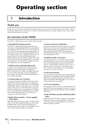
... of an input channel in memory as scene saving and recall can also be used to deliver up to four PM5D units, or one PM5D and one Yamaha DM2000/02R96 unit, can operate the fader, pan, cue, and on an analog mixer. The REV-X reverb effect sold Add-On Effects packages can be ...stored in a safe place. Effects, input/output patching, input channel/output channel settings, internal head amp (PM5D-RH model only) or external ...
... of an input channel in memory as scene saving and recall can also be used to deliver up to four PM5D units, or one PM5D and one Yamaha DM2000/02R96 unit, can operate the fader, pan, cue, and on an analog mixer. The REV-X reverb effect sold Add-On Effects packages can be ...stored in a safe place. Effects, input/output patching, input channel/output channel settings, internal head amp (PM5D-RH model only) or external ...
Owner's Manual
Page 14
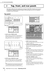
... For the PM5D-RH model, input sensitivity and phantom power on /off status and send level of the signals sent from input channels to MIX buses, and adjusts the master level of the signals sent from rear panel INPUT jacks 1-48 and ST IN jacks 1- 4. D FADER FLIP/ENCODER MODE section... rear panels This chapter explains the names and functions of each section of the top panel are controlled by key operations (➥ p.100). 14 PM5D/PM5D-RH Owner's Manual Operating section G SELECTED CHANNEL section In this section you can adjust the sensitivity of the ana- 3 log signals being input from...
... For the PM5D-RH model, input sensitivity and phantom power on /off status and send level of the signals sent from input channels to MIX buses, and adjusts the master level of the signals sent from rear panel INPUT jacks 1-48 and ST IN jacks 1- 4. D FADER FLIP/ENCODER MODE section... rear panels This chapter explains the names and functions of each section of the top panel are controlled by key operations (➥ p.100). 14 PM5D/PM5D-RH Owner's Manual Operating section G SELECTED CHANNEL section In this section you can adjust the sensitivity of the ana- 3 log signals being input from...
Owner's Manual
Page 15
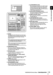
... groups for mute groups 1-8 are also performed in the display (➥ p.20). Note Before moving the upper part of the display frame forward or backward. J FADER MODE section Here you make system-wide settings and control mix parameters for a channel (➥ p.91). I Display This display shows the information you need to... lets you can select the combination of channels or DCA groups that will be controlled by moving the PM5D, you move the pointer (the arrow displayed in the screen) or cursor (the red frame indicating a selection) in the display and edit the parameter value ...
... groups for mute groups 1-8 are also performed in the display (➥ p.20). Note Before moving the upper part of the display frame forward or backward. J FADER MODE section Here you make system-wide settings and control mix parameters for a channel (➥ p.91). I Display This display shows the information you need to... lets you can select the combination of channels or DCA groups that will be controlled by moving the PM5D, you move the pointer (the arrow displayed in the screen) or cursor (the red frame indicating a selection) in the display and edit the parameter value ...
Owner's Manual
Page 19
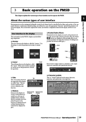
... left and right allow you want to operate the PM5D. 3 About the various types of user interface Basic operation on the PM5D Basic parameters such as mixing and editing the sound of each channel can be gray.) Knob Box Fader ❏ Cursor The red frame shown in the box...the appropriate "function" and edit the parameter values in the display. 3 Basic operation on the PM5D This chapter explains the various types of user interface used to control next. ❏ Knobs/Faders/Boxes Knobs/faders in the display are displayed in red or blue); Buttons that are turned off (gray) ...
... left and right allow you want to operate the PM5D. 3 About the various types of user interface Basic operation on the PM5D Basic parameters such as mixing and editing the sound of each channel can be gray.) Knob Box Fader ❏ Cursor The red frame shown in the box...the appropriate "function" and edit the parameter values in the display. 3 Basic operation on the PM5D This chapter explains the various types of user interface used to control next. ❏ Knobs/Faders/Boxes Knobs/faders in the display are displayed in red or blue); Buttons that are turned off (gray) ...
Owner's Manual
Page 22
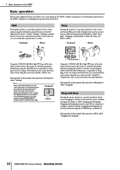
...pad (or mouse) button while moving up/down/left/right is called "clicking." Dragging is used mainly to adjust the value of a knob or fader. • Track pad • Mouse Drag Drag Using the CURSOR keys of the data entry section to move the cursor to a desired parameter... result as if you can perform the same action using the CURSOR keys or keyboard. Click Moving the pointer to a specific parameter in the PM5D's display by combining the operations described here. Subsequently in this manual, this operation will simply be called "dragging and dropping." Clicking is called...
...pad (or mouse) button while moving up/down/left/right is called "clicking." Dragging is used mainly to adjust the value of a knob or fader. • Track pad • Mouse Drag Drag Using the CURSOR keys of the data entry section to move the cursor to a desired parameter... result as if you can perform the same action using the CURSOR keys or keyboard. Click Moving the pointer to a specific parameter in the PM5D's display by combining the operations described here. Subsequently in this manual, this operation will simply be called "dragging and dropping." Clicking is called...
Owner's Manual
Page 25
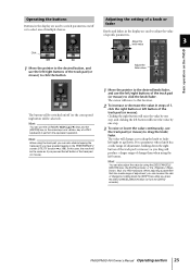
Adjust the fader value Basic operation on the PM5D The button will be switched on /off (or the corresponding button will lower the ...keyboard) to perform the equivalent operation. Hint You can use the track pad (or mouse) to drag the knob/ fader. Hint You can also adjust the value by holding down the right button of the track pad (or mouse) as...the knob/fader. In this case, the result will be selected). Clicking the right button will raise the value by tapping the track pad if you press the [DEC/CANCEL]/[INC/OK] keys (or turn the [DATA] encoder). PM5D/PM5D-RH Owner...
Adjust the fader value Basic operation on the PM5D The button will be switched on /off (or the corresponding button will lower the ...keyboard) to perform the equivalent operation. Hint You can use the track pad (or mouse) to drag the knob/ fader. Hint You can also adjust the value by holding down the right button of the track pad (or mouse) as...the knob/fader. In this case, the result will be selected). Clicking the right button will raise the value by tapping the track pad if you press the [DEC/CANCEL]/[INC/OK] keys (or turn the [DATA] encoder). PM5D/PM5D-RH Owner...
Owner's Manual
Page 34
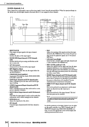
... that cuts the region below the specified frequency. • 4 BAND EQ (4 band equalizer) A parametric EQ with four bands; immediately before the 4-band EQ, pre-fader, or post-fader. • INSERT (Input channels and ST IN channels only) Here you can switch the insert-out and insert-in , allowing an external effect processor... between channels. • LEVEL/DCA 1-8 Adjusts the input level of an input channel, you can be used to make fine adjustments in the screen. 34 PM5D/PM5D-RH Owner's Manual Operating section
... that cuts the region below the specified frequency. • 4 BAND EQ (4 band equalizer) A parametric EQ with four bands; immediately before the 4-band EQ, pre-fader, or post-fader. • INSERT (Input channels and ST IN channels only) Here you can switch the insert-out and insert-in , allowing an external effect processor... between channels. • LEVEL/DCA 1-8 Adjusts the input level of an input channel, you can be used to make fine adjustments in the screen. 34 PM5D/PM5D-RH Owner's Manual Operating section
Owner's Manual
Page 37
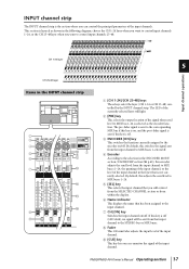
...LED dark), no signal will light. I [CUE] key This key lets you can control the principal parameters of the input channels. H Fader This 100 mm fader adjusts the input level of the input channel. C ENCODER [ON] key This switches the function currently assigned to the input channel. By ...default, this key is off . PM5D/PM5D-RH Owner's Manual Operating section 37 The pre-fader signal is sent to MIX buses 1-24. INPUT channel strip The INPUT channel strip is the section where you cue-...
...LED dark), no signal will light. I [CUE] key This key lets you can control the principal parameters of the input channels. H Fader This 100 mm fader adjusts the input level of the input channel. C ENCODER [ON] key This switches the function currently assigned to the input channel. By ...default, this key is off . PM5D/PM5D-RH Owner's Manual Operating section 37 The pre-fader signal is sent to MIX buses 1-24. INPUT channel strip The INPUT channel strip is the section where you cue-...
Owner's Manual
Page 39
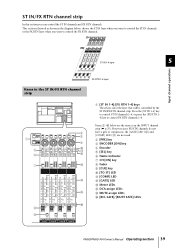
... are the same as shown in the diagram below are not used. B [PRE] key 4 C ENCODER [ON] key J D Encoder K L E [SEL] key F Name indicator G CH [ON] key M H Fader I [CUE] key J [TO ST] LED K [COMP] LED N L [GATE] LED M Meter LEDs N DCA assign LEDs O O MUTE assign LEDs P [RCL SAFE]/[MUTE SAFE] LEDs... P PM5D/PM5D-RH Owner's Manual Operating section 39 ST IN/FX RTN channel strip In this section you want to control the ST IN channels, or the ...
... are the same as shown in the diagram below are not used. B [PRE] key 4 C ENCODER [ON] key J D Encoder K L E [SEL] key F Name indicator G CH [ON] key M H Fader I [CUE] key J [TO ST] LED K [COMP] LED N L [GATE] LED M Meter LEDs N DCA assign LEDs O O MUTE assign LEDs P [RCL SAFE]/[MUTE SAFE] LEDs... P PM5D/PM5D-RH Owner's Manual Operating section 39 ST IN/FX RTN channel strip In this section you want to control the ST IN channels, or the ...
Owner's Manual
Page 40
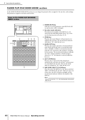
...24) selected by the MIX SEND SELECT keys (6) or the encoder function selected by the encoders. The encoder mode indicator will be controlled by the faders and encoders will indicate "Pn" while this key is on . 6 F MIX SEND SELECT [1]-[24] keys These keys select the MIX bus (1-24...) whose send level will be exchanged. Hint If you turn off. 40 PM5D/PM5D-RH Owner's Manual Operating section C [PAN] key 2 345 This key selects pan (balance) as the parameter controlled by keys 3-5. ter controlled by the ...
...24) selected by the MIX SEND SELECT keys (6) or the encoder function selected by the encoders. The encoder mode indicator will be controlled by the faders and encoders will indicate "Pn" while this key is on . 6 F MIX SEND SELECT [1]-[24] keys These keys select the MIX bus (1-24...) whose send level will be exchanged. Hint If you turn off. 40 PM5D/PM5D-RH Owner's Manual Operating section C [PAN] key 2 345 This key selects pan (balance) as the parameter controlled by keys 3-5. ter controlled by the ...
Owner's Manual
Page 41
... and the MIX bus send level. At [ALT LAYER] key Input level for input channels Selecting the function of the encoders Exchanging the fader and encoder When the PM5D is in the default state, the encoders of the functions INPUT channel strip and ST IN/FX RTN channel strip are in a "front... signal sent from channel (currently selected layer) to MIX bus Note • The DCA channel strip and STEREO A/B channel strip are in a "front/rear" relation. PM5D/PM5D-RH Owner's Manual Operating section 41 In the ST IN/FX RTN channel strip, the ST IN 1-4 layer and the FX RTN 1-4 layer are not...
... and the MIX bus send level. At [ALT LAYER] key Input level for input channels Selecting the function of the encoders Exchanging the fader and encoder When the PM5D is in the default state, the encoders of the functions INPUT channel strip and ST IN/FX RTN channel strip are in a "front... signal sent from channel (currently selected layer) to MIX bus Note • The DCA channel strip and STEREO A/B channel strip are in a "front/rear" relation. PM5D/PM5D-RH Owner's Manual Operating section 41 In the ST IN/FX RTN channel strip, the ST IN 1-4 layer and the FX RTN 1-4 layer are not...
Owner's Manual
Page 42
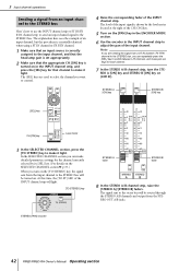
... is correctly assigned to the input channel, and that the head amp gain is set appropriately. 2 Make sure that channel to control. 4 Raise the corresponding fader of the INPUT channel strip. STEREO A [ON] key STEREO B [ON] key [SEL] key CH [ON] key Level meter 3 In the SELECTED CHANNEL section, press ... located at the right of the input signal is turned on . In the SELECTED CHANNEL section you can make it light. STEREO [PAN] encoder 42 PM5D/PM5D-RH Owner's Manual Operating section The level of the CH [ON] key. 5 Turn on (LED lit). The signal sent to the stereo bus will ...
... is correctly assigned to the input channel, and that the head amp gain is set appropriately. 2 Make sure that channel to control. 4 Raise the corresponding fader of the INPUT channel strip. STEREO A [ON] key STEREO B [ON] key [SEL] key CH [ON] key Level meter 3 In the SELECTED CHANNEL section, press ... located at the right of the input signal is turned on . In the SELECTED CHANNEL section you can make it light. STEREO [PAN] encoder 42 PM5D/PM5D-RH Owner's Manual Operating section The level of the CH [ON] key. 5 Turn on (LED lit). The signal sent to the stereo bus will ...
Owner's Manual
Page 43
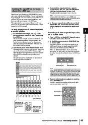
... can use the encoders of the MIX section to adjust the send levels from the input channel to the MIX bus. Make sure that the FADER [FLIP] key is lit, you can be switched on . cate the approximate send level. channel. The explanation here uses an input channel as the encoder... to turn it . In this state, the encoders of the channel strip adjust the send level to the MIX bus. MIX [ON] key MIX encoder PM5D/PM5D-RH Owner's Manual Operating section 43 In this state, you control the signals sent to MIX buses 1-24 and the signals output from a specific channel...
... can use the encoders of the MIX section to adjust the send levels from the input channel to the MIX bus. Make sure that the FADER [FLIP] key is lit, you can be switched on . cate the approximate send level. channel. The explanation here uses an input channel as the encoder... to turn it . In this state, the encoders of the channel strip adjust the send level to the MIX bus. MIX [ON] key MIX encoder PM5D/PM5D-RH Owner's Manual Operating section 43 In this state, you control the signals sent to MIX buses 1-24 and the signals output from a specific channel...
Owner's Manual
Page 44
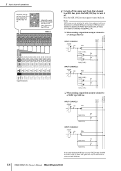
... switched (in units of the signal sent from the input channel to the MIX bus. MIX1 (VARI) LEVEL ON LEVEL ON MIX2 (VARI) INPUT CHANNEL 2 FADER ON PAN MIX1 (VARI) LEVEL ON LEVEL ON MIX2 (VARI) ❏ When sending a signal from an input channel to FIXED mode, the MIX encoders have... off the signal sent from that channel to a MIX bus, press the MIX [ON] key to turn it off by the MIX [ON] key. 44 PM5D/PM5D-RH Owner's Manual Operating section Input channels Adjusts the send level of two adjacent odd-numbered/even-numbered MIX buses) between VARI type (send levels...
... switched (in units of the signal sent from the input channel to the MIX bus. MIX1 (VARI) LEVEL ON LEVEL ON MIX2 (VARI) INPUT CHANNEL 2 FADER ON PAN MIX1 (VARI) LEVEL ON LEVEL ON MIX2 (VARI) ❏ When sending a signal from an input channel to FIXED mode, the MIX encoders have... off the signal sent from that channel to a MIX bus, press the MIX [ON] key to turn it off by the MIX [ON] key. 44 PM5D/PM5D-RH Owner's Manual Operating section Input channels Adjusts the send level of two adjacent odd-numbered/even-numbered MIX buses) between VARI type (send levels...
Owner's Manual
Page 45
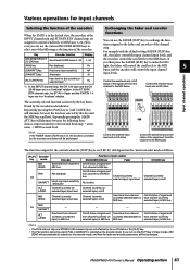
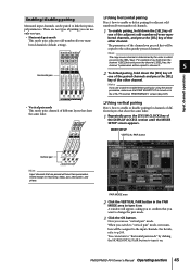
... Input channel operations • Vertical pair mode This mode pairs channels of different layers that share the same fader. ❏ Using vertical pairing Here's how to enable or disable pairing for channels of different layers that ... [SEL] key of the other channel. A window will appear, asking you to confirm that share the same fader. 1 Repeatedly press the [SYS/W.CLOCK] key of pairing; MIXER SETUP VERTICAL PAIR button Vertical pair Hint Input ... order in the UTILITY function PREFERENCE 1 screen (➥ p.187). PM5D/PM5D-RH Owner's Manual Operating section 45
... Input channel operations • Vertical pair mode This mode pairs channels of different layers that share the same fader. ❏ Using vertical pairing Here's how to enable or disable pairing for channels of different layers that ... [SEL] key of the other channel. A window will appear, asking you to confirm that share the same fader. 1 Repeatedly press the [SYS/W.CLOCK] key of pairing; MIXER SETUP VERTICAL PAIR button Vertical pair Hint Input ... order in the UTILITY function PREFERENCE 1 screen (➥ p.187). PM5D/PM5D-RH Owner's Manual Operating section 45


