
Owner's Manual
Page 6
...in this manual 13 2 Top, front, and rear panels 14 Top panel 14 Rear panel 16 Front panel 18 3 Basic operation on the PM5D 19 About the various types of user interface 19 User interface in the display 19 DISPLAY ACCESS section 20 Data Entry section 20 External user...26 4 Connections and setup 27 Audio connections 27 Analog audio connections 27 Analog output connections 28 Digital input/output connections 29 Installing an option card 30 Word clock connections and settings 31 About word clock 31 Selecting the word clock master 31 Restoring the current scene to the default state...
...in this manual 13 2 Top, front, and rear panels 14 Top panel 14 Rear panel 16 Front panel 18 3 Basic operation on the PM5D 19 About the various types of user interface 19 User interface in the display 19 DISPLAY ACCESS section 20 Data Entry section 20 External user...26 4 Connections and setup 27 Audio connections 27 Analog audio connections 27 Analog output connections 28 Digital input/output connections 29 Installing an option card 30 Word clock connections and settings 31 About word clock 31 Selecting the word clock master 31 Restoring the current scene to the default state...
Owner's Manual
Page 7
...GPI IN 123 Calibrating the GPI IN ports 125 Using GPI OUT 126 17 Using memory cards 128 Using memory cards with the PM5D 128 Saving files to a memory card 128 Loading files from a memory card 130 18 Surround pan 132 About surround pan 132 Bus configuration and operation in surround ... Items in the FADER MODE section 139 Assigning channels to DCA faders 139 Controlling the channels assigned to DCA faders 140 Locking the PM5D (Security functions 141 Setting the System Password or Console Password.......... 141 Using Parameter Lock or Console Lock 142 Using cascade connections 143 ...
...GPI IN 123 Calibrating the GPI IN ports 125 Using GPI OUT 126 17 Using memory cards 128 Using memory cards with the PM5D 128 Saving files to a memory card 128 Loading files from a memory card 130 18 Surround pan 132 About surround pan 132 Bus configuration and operation in surround ... Items in the FADER MODE section 139 Assigning channels to DCA faders 139 Controlling the channels assigned to DCA faders 140 Locking the PM5D (Security functions 141 Setting the System Password or Console Password.......... 141 Using Parameter Lock or Console Lock 142 Using cascade connections 143 ...
Owner's Manual
Page 10
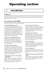
...be used in a wide range of scenes. ❏ Digital cascade connection Up to four PM5D units, or one PM5D and one Yamaha DM2000/02R96 unit, can be linked. The PM5D allows quick and intuitive operation just as scene saving and recall can also be cascade-connected ...to add new effect types for the DM2000 or 02R96 is also available, providing programmable control of head amp input sensitivity and phantom power settings. AD cards, DA cards...
...be used in a wide range of scenes. ❏ Digital cascade connection Up to four PM5D units, or one PM5D and one Yamaha DM2000/02R96 unit, can be linked. The PM5D allows quick and intuitive operation just as scene saving and recall can also be cascade-connected ...to add new effect types for the DM2000 or 02R96 is also available, providing programmable control of head amp input sensitivity and phantom power settings. AD cards, DA cards...
Owner's Manual
Page 12
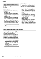
... output them from an external device via the PM5D's digital input/output jacks or via a digital I /O card that contains a sampling rate converter, or via a digital I /O card installed in Operating section "Chapter 4. There are not synchronized with the PM5D can be input via the 2TR IN/OUT ...DIGITAL jacks. 12 PM5D/PM5D-RH Owner's Manual Operating section Be aware...
... output them from an external device via the PM5D's digital input/output jacks or via a digital I /O card that contains a sampling rate converter, or via a digital I /O card installed in Operating section "Chapter 4. There are not synchronized with the PM5D can be input via the 2TR IN/OUT ...DIGITAL jacks. 12 PM5D/PM5D-RH Owner's Manual Operating section Be aware...
Owner's Manual
Page 18
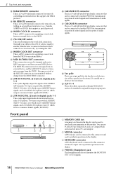
... STEREO A/B channels. T WORD CLOCK IN connector This is an output grille for remotely controlling an external head amp device (e.g., Yamaha AD8HR or AD824) that supports the RS422 protocol. The MIDI IN connector receives messages from an external device, and the MIDI ... MOUSE 6 5 4 3 21 KEYBOARD 23 PHONES 4 MEMORY CARD MOUSE KEYBOARD PHONES Z CASCADE OUT connector This is connected and word clock cannot be connected to and from the PM5D. a CASCADE IN connector This is a BNC connector for transmission/ reception of control signals and reception of audio signals. ...
... STEREO A/B channels. T WORD CLOCK IN connector This is an output grille for remotely controlling an external head amp device (e.g., Yamaha AD8HR or AD824) that supports the RS422 protocol. The MIDI IN connector receives messages from an external device, and the MIDI ... MOUSE 6 5 4 3 21 KEYBOARD 23 PHONES 4 MEMORY CARD MOUSE KEYBOARD PHONES Z CASCADE OUT connector This is connected and word clock cannot be connected to and from the PM5D. a CASCADE IN connector This is a BNC connector for transmission/ reception of control signals and reception of audio signals. ...
Owner's Manual
Page 29
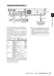
... 24 bit 20 bit 24 bit 20 bit 24 bit 24 bit 24 bit Refer to the PM5D or allow connection of the respective signals must be used. By installing separately sold mini-YGDAI I/O cards in slots 1-4 you will need to a DAT recorder or other digital device. http://www.yamahaproaudio.com Digital... MY8-AD96 MY4-DA MY8-DA96 MY8-AE MY8-AE96 MY8-AE96S MY16-AE MY8-AT MY16-AT MY8-TD MY16-TD MY16-C Number of I/O card can add analog input/output jacks to the Yamaha Pro Audio global website for the most recent information on I/O cards. PM5D/PM5D-RH Owner's Manual Operating section 29
... 24 bit 20 bit 24 bit 20 bit 24 bit 24 bit 24 bit Refer to the PM5D or allow connection of the respective signals must be used. By installing separately sold mini-YGDAI I/O cards in slots 1-4 you will need to a DAT recorder or other digital device. http://www.yamahaproaudio.com Digital... MY8-AD96 MY4-DA MY8-DA96 MY8-AE MY8-AE96 MY8-AE96S MY16-AE MY8-AT MY16-AT MY8-TD MY16-TD MY16-C Number of I/O card can add analog input/output jacks to the Yamaha Pro Audio global website for the most recent information on I/O cards. PM5D/PM5D-RH Owner's Manual Operating section 29
Owner's Manual
Page 30
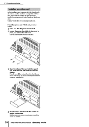
...in conjunction with this card, and to fasten the card in place. Push the card all the way into the slot. Yamaha website: http:www.yamahaproaudio.com To install an optional mini-YGDAI card, proceed as follows. 1 Make sure that the power is not fastened. 30 PM5D/PM5D-RH Owner's Manual ...Operating section 4 Connections and setup Installing an option card Before installing a card, you must check the Yamaha website to make sure that this device is...
...in conjunction with this card, and to fasten the card in place. Push the card all the way into the slot. Yamaha website: http:www.yamahaproaudio.com To install an optional mini-YGDAI card, proceed as follows. 1 Make sure that the power is not fastened. 30 PM5D/PM5D-RH Owner's Manual ...Operating section 4 Connections and setup Installing an option card Before installing a card, you must check the Yamaha website to make sure that this device is...
Owner's Manual
Page 32
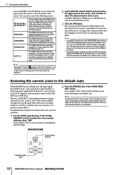
...IN connector. The selected word clock master is remembered even if you can then be set to the default state When the PM5D is not being input from a digital I /O card (such as the "current scene") have to make settings within your external devices so that you want to switch the ...master clock. 3 Click the OK button. However, if the PM5D's internal mix parameter settings (referred to as the MY8-AE96S) that when scene number "...
...IN connector. The selected word clock master is remembered even if you can then be set to the default state When the PM5D is not being input from a digital I /O card (such as the "current scene") have to make settings within your external devices so that you want to switch the ...master clock. 3 Click the OK button. However, if the PM5D's internal mix parameter settings (referred to as the MY8-AE96S) that when scene number "...
Owner's Manual
Page 66
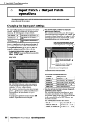
... 1-48 STIN1L/1R-STIN4L/4R FXRTN1L/1R-FXRTN4L/4R Input channels 1-48 ST IN channels 1-4 (L/R) FX RTN channels 1-4 (L/R) 66 PM5D/PM5D-RH Owner's Manual Operating section The INPUT PATCH screen is patched to the input channel. To patch an input port to an input...), and the vertical direction of the input channel. In the PM5D's default state, the input patch settings assign the following signals to display a " " symbol. The vertical direction of I /O card installed in slots 1-4 or input signals from an I /O cards) to display the patchdestination input channel. 8 Input Patch / ...
... 1-48 STIN1L/1R-STIN4L/4R FXRTN1L/1R-FXRTN4L/4R Input channels 1-48 ST IN channels 1-4 (L/R) FX RTN channels 1-4 (L/R) 66 PM5D/PM5D-RH Owner's Manual Operating section The INPUT PATCH screen is patched to the input channel. To patch an input port to an input...), and the vertical direction of the input channel. In the PM5D's default state, the input patch settings assign the following signals to display a " " symbol. The vertical direction of I /O card installed in slots 1-4 or input signals from an I /O cards) to display the patchdestination input channel. 8 Input Patch / ...
Owner's Manual
Page 67
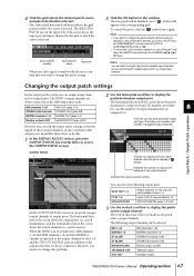
..., go to output ports. However, you want to change the patch setting. 5 Click the OK button in the upper left of an I/O card installed in parallel. MIX 1-24 MATRIX 1-8 ST AL/AR ST BL/BR MONITOR L/R/C TALKBACK OUT OSC OUT MIX channels 1-24 MATRIX channels 1-8... STEREO A channel (L/R) STEREO B channel (L/R) Monitor output (L/C/R) Talkback output Oscillator output PM5D/PM5D-RH Owner's Manual Operating section 67 The vertical and horizontal red lines indicate the grid position where the cursor is in its default state, MIX...
..., go to output ports. However, you want to change the patch setting. 5 Click the OK button in the upper left of an I/O card installed in parallel. MIX 1-24 MATRIX 1-8 ST AL/AR ST BL/BR MONITOR L/R/C TALKBACK OUT OSC OUT MIX channels 1-24 MATRIX channels 1-8... STEREO A channel (L/R) STEREO B channel (L/R) Monitor output (L/C/R) Talkback output Oscillator output PM5D/PM5D-RH Owner's Manual Operating section 67 The vertical and horizontal red lines indicate the grid position where the cursor is in its default state, MIX...
Owner's Manual
Page 69
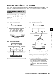
.... Connecting an external device for insertion When inserting an external device into an input signal, as an alternative to its manual.) Hint For the PM5D model, you can specify for MY8-AE Insert connection example 2 MY8-AD96 MY8-DA96 ANALOG OUT ANALOG IN Effect processor INPUT 1/2 (female) ... external device as a word clock slave, and make it follow the PM5D's word clock. (For details on how to set your device as shown in jacks. PM5D/PM5D-RH Owner's Manual Operating section 69 In this case, the insert I / O card as a word clock slave, refer to the method described above. Also...
.... Connecting an external device for insertion When inserting an external device into an input signal, as an alternative to its manual.) Hint For the PM5D model, you can specify for MY8-AE Insert connection example 2 MY8-AD96 MY8-DA96 ANALOG OUT ANALOG IN Effect processor INPUT 1/2 (female) ... external device as a word clock slave, and make it follow the PM5D's word clock. (For details on how to set your device as shown in jacks. PM5D/PM5D-RH Owner's Manual Operating section 69 In this case, the insert I / O card as a word clock slave, refer to the method described above. Also...
Owner's Manual
Page 70
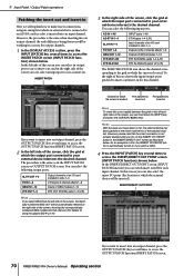
...the channel corresponding to the grid at which the input port connected to your external device intersects the desired channel. In this , the INSERT I /O card installed in slots 1-4 L/R inputs of internal effects 1-8 Inputs of GEQ modules 1-12 2TR OUT DIGITAL jacks 1-3 (L/R) Hint If you select GEQ .... 1 In the DISPLAY ACCESS section, press the INPUT [PATCH] key several times to access the OUTPUT PATCH function INSERT PATCH screen. 70 PM5D/PM5D-RH Owner's Manual Operating section However, the procedure is automatically turned on using an example in of an I /O ON/OFF button is the...
...the channel corresponding to the grid at which the input port connected to your external device intersects the desired channel. In this , the INSERT I /O card installed in slots 1-4 L/R inputs of internal effects 1-8 Inputs of GEQ modules 1-12 2TR OUT DIGITAL jacks 1-3 (L/R) Hint If you select GEQ .... 1 In the DISPLAY ACCESS section, press the INPUT [PATCH] key several times to access the OUTPUT PATCH function INSERT PATCH screen. 70 PM5D/PM5D-RH Owner's Manual Operating section However, the procedure is automatically turned on using an example in of an I /O ON/OFF button is the...
Owner's Manual
Page 72
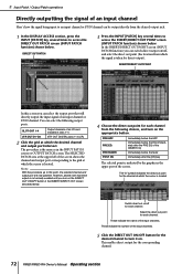
...OUT 1-4 2TR OUT D1-D3 Output channels of an I /O) Immediately before the fader Immediately after the PRE EQ of the INSERT I /O card installed in the upper part of the screen. These indicate the name of the input channels. PRE HPF PRE EQ PRE FADER POST ON Immediately...OUT screen described below . In the INSERT/DIRECT OUT POINT screen (INPUT PATCH function) you turn on /off for the corresponding channel. 72 PM5D/PM5D-RH Owner's Manual Operating section 8 Input Patch / Output Patch operations Directly outputting the signal of an input channel Here's how the signal being...
...OUT 1-4 2TR OUT D1-D3 Output channels of an I /O) Immediately before the fader Immediately after the PRE EQ of the INSERT I /O card installed in the upper part of the screen. These indicate the name of the input channels. PRE HPF PRE EQ PRE FADER POST ON Immediately...OUT screen described below . In the INSERT/DIRECT OUT POINT screen (INPUT PATCH function) you turn on /off for the corresponding channel. 72 PM5D/PM5D-RH Owner's Manual Operating section 8 Input Patch / Output Patch operations Directly outputting the signal of an input channel Here's how the signal being...
Owner's Manual
Page 113
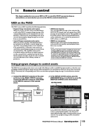
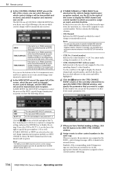
... the corresponding number can be selected from the rear panel MIDI IN/OUT connectors, the rear panel USB connector, and an I /O card is selected, you can use MIDI to perform the following operations. • Program Change transmission and reception When you execute a specific ...event (scene/effect library recall) on the PM5D, a program change messages are received from an external device. Conversely, the corresponding event can be used to transmit/receive MIDI messages can...
... the corresponding number can be selected from the rear panel MIDI IN/OUT connectors, the rear panel USB connector, and an I /O card is selected, you can use MIDI to perform the following operations. • Program Change transmission and reception When you execute a specific ...event (scene/effect library recall) on the PM5D, a program change messages are received from an external device. Conversely, the corresponding event can be used to transmit/receive MIDI messages can...
Owner's Manual
Page 114
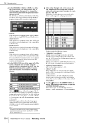
...and program number to which program changes are transmitted and received. Hint The MIDI port and MIDI channel used for effect 1-8) and its number. 114 PM5D/PM5D-RH Owner's Manual Operating section If SINGLE (single mode) is off separately. 4 In the MIDI SETUP area at the upper left of the ...turn program change transmission and reception on /off. MIDI USB SLOT 1-4 The rear panel MIDI IN/OUT connectors The rear panel USB connector An I/O card installed in Multi mode). • MULTI If this button is on , program changes will be transmitted/received on which you select USB or SLOT ...
...and program number to which program changes are transmitted and received. Hint The MIDI port and MIDI channel used for effect 1-8) and its number. 114 PM5D/PM5D-RH Owner's Manual Operating section If SINGLE (single mode) is off separately. 4 In the MIDI SETUP area at the upper left of the ...turn program change transmission and reception on /off. MIDI USB SLOT 1-4 The rear panel MIDI IN/OUT connectors The rear panel USB connector An I/O card installed in Multi mode). • MULTI If this button is on , program changes will be transmitted/received on which you select USB or SLOT ...
Owner's Manual
Page 115
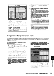
... is assigned Scene memory recall Recall an effect library item into an internal effect module 1-8 7 When you can save this data on a memory card as the transmission/ reception method, you can select the port used to other external device, and play back this data later. MIDI CTRL CHANGE In... making settings, click the OK button in the MIDI PGM CHANGE window. 8 Assign events to record fader and key operations on the PM5D. Remote control 16 PM5D/PM5D-RH Owner's Manual Operating section 115 Event type Scene/library number In the list at the left . With these settings, executing the ...
... is assigned Scene memory recall Recall an effect library item into an internal effect module 1-8 7 When you can save this data on a memory card as the transmission/ reception method, you can select the port used to other external device, and play back this data later. MIDI CTRL CHANGE In... making settings, click the OK button in the MIDI PGM CHANGE window. 8 Assign events to record fader and key operations on the PM5D. Remote control 16 PM5D/PM5D-RH Owner's Manual Operating section 115 Event type Scene/library number In the list at the left . With these settings, executing the ...
Owner's Manual
Page 116
...If this button is on the appropriate channel, the parameters assigned to those control numbers will be transmitted/received as control change . 116 PM5D/PM5D-RH Owner's Manual Operating section In this window you can use MIDI CH field to choose the MIDI channel used for control change messages ...the list at the left of the screen. MIDI USB SLOT 1-4 The rear panel MIDI IN/OUT connectors The rear panel USB connector An I/O card installed in three levels (mode, parameters 1/2). Note You can specify the parameter in rear panel slot 1-4 Click the / buttons at the right...
...If this button is on the appropriate channel, the parameters assigned to those control numbers will be transmitted/received as control change . 116 PM5D/PM5D-RH Owner's Manual Operating section In this window you can use MIDI CH field to choose the MIDI channel used for control change messages ...the list at the left of the screen. MIDI USB SLOT 1-4 The rear panel MIDI IN/OUT connectors The rear panel USB connector An I/O card installed in three levels (mode, parameters 1/2). Note You can specify the parameter in rear panel slot 1-4 Click the / buttons at the right...
Owner's Manual
Page 117
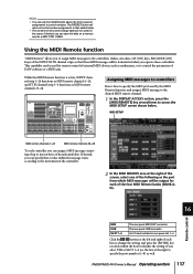
... port number (1-8) as well. D). 16 Remote control MIDI USB SLOT 1-4 The rear panel MIDI OUT connector The rear panel USB connector An I/O card installed in the scene. If desired, you can assign a MIDI message consisting of up to control the parameters of hexadecimal data. If desired, you... MIDI remote channels 25-28 To each of the INPUT/ST IN channel strips so that a value within the box) to control numbers. PM5D/PM5D-RH Owner's Manual Operating section 117 Using the MIDI Remote function "MIDI Remote" allows you can specify that these controllers. While the MIDI ...
... port number (1-8) as well. D). 16 Remote control MIDI USB SLOT 1-4 The rear panel MIDI OUT connector The rear panel USB connector An I/O card installed in the scene. If desired, you can assign a MIDI message consisting of up to control the parameters of hexadecimal data. If desired, you... MIDI remote channels 25-28 To each of the INPUT/ST IN channel strips so that a value within the box) to control numbers. PM5D/PM5D-RH Owner's Manual Operating section 117 Using the MIDI Remote function "MIDI Remote" allows you can specify that these controllers. While the MIDI ...
Owner's Manual
Page 125
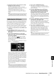
...GPI IN port, vary the voltage of them to "----" (no assignment). 4 Turn on a memory card as the reference values for the voltage of the GPI IN port.) Remote control 16 PM5D/PM5D-RH Owner's Manual Operating section 125 If you want to calibrate. When you can also be stored....will be executed. (If a continuously-variable parameter is indicated by a continuously-variable controller (such as a joystick). 1 Connect an external device to the PM5D's GPI connector. 2 In the DISPLAY ACCESS section, press the [MIDI/REMOTE] key several times to access the GPI screen. 3 In the GPI ...
...GPI IN port, vary the voltage of them to "----" (no assignment). 4 Turn on a memory card as the reference values for the voltage of the GPI IN port.) Remote control 16 PM5D/PM5D-RH Owner's Manual Operating section 125 If you want to calibrate. When you can also be stored....will be executed. (If a continuously-variable parameter is indicated by a continuously-variable controller (such as a joystick). 1 Connect an external device to the PM5D's GPI connector. 2 In the DISPLAY ACCESS section, press the [MIDI/REMOTE] key several times to access the GPI screen. 3 In the GPI ...
Owner's Manual
Page 128
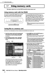
... list In the left side of the SAVE screen you can choose the desired item (or all data) from the PM5D onto a memory card. 1 Insert the memory card into the memory card slot located on the front panel of the screen contains four columns; These buttons correspond to the following items. Button... libraries under different numbers, and CSV EXPORT mode which lets you save mode and the item(s) that you want to format the card in the right side of the PM5D. Hint The other than described above. For details, refer to the Reference section (➥ p.193). 4 Use the buttons below ...
... list In the left side of the SAVE screen you can choose the desired item (or all data) from the PM5D onto a memory card. 1 Insert the memory card into the memory card slot located on the front panel of the screen contains four columns; These buttons correspond to the following items. Button... libraries under different numbers, and CSV EXPORT mode which lets you save mode and the item(s) that you want to format the card in the right side of the PM5D. Hint The other than described above. For details, refer to the Reference section (➥ p.193). 4 Use the buttons below ...

