
Owner's Manual
Page 3
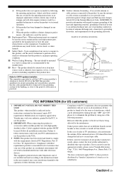
... the product exhibits a distinct change the lead-in to CATV system installer: This reminder is 300 ohm ribbon lead, change in proper operating condition. 22 Wall or Ceiling Mounting - The unit should be sure the service technician has used replacement parts specified by the manufacturer or have the same characteristics as an improper adjustment of other controls may cause interference harmful...
... the product exhibits a distinct change the lead-in to CATV system installer: This reminder is 300 ohm ribbon lead, change in proper operating condition. 22 Wall or Ceiling Mounting - The unit should be sure the service technician has used replacement parts specified by the manufacturer or have the same characteristics as an improper adjustment of other controls may cause interference harmful...

Owner's Manual
Page 5
..., or other components........ 57 Setting remote control codes 59 Advanced setup 60 PREPARATION Connections 10 Rear panel 10 Placing speakers 11 Connecting speakers 12 Setting the speaker impedance 13 Information on jacks and cable plugs 14 Information on HDMI 15 Connecting video components 16 Connecting audio components 19 Using the VIDEO AUX jacks on the front panel ........ 20 Connecting the FM and AM antennas 20 Connecting the power cable 21 Turning on and off the power 21 Front panel display 22 Optimizing the speaker setting for your listening room 24 Using AUTO SETUP 24...
..., or other components........ 57 Setting remote control codes 59 Advanced setup 60 PREPARATION Connections 10 Rear panel 10 Placing speakers 11 Connecting speakers 12 Setting the speaker impedance 13 Information on jacks and cable plugs 14 Information on HDMI 15 Connecting video components 16 Connecting audio components 19 Using the VIDEO AUX jacks on the front panel ........ 20 Connecting the FM and AM antennas 20 Connecting the power cable 21 Turning on and off the power 21 Front panel display 22 Optimizing the speaker setting for your listening room 24 Using AUTO SETUP 24...

Owner's Manual
Page 8
... video output jack. ❏ Video monitor 1 Select a TV monitor, video monitor or projector equipped with a composite video input jack. ❏ Video cable 2 Select an RCA composite video cable. ❏ Digital coaxial audio cable 1 Step 3: Turn on the power and press SCENE 1 button ☞ P. 8 Enjoy DVD playback! 4 En Video monitor Front left speaker Front right speaker Subwoofer Surround right speaker Preparation: Check the items In these steps, you need the following supplied accessories. ❏ Indoor FM antenna ❏ AM loop antenna Center speaker DVD player Surround...
... video output jack. ❏ Video monitor 1 Select a TV monitor, video monitor or projector equipped with a composite video input jack. ❏ Video cable 2 Select an RCA composite video cable. ❏ Digital coaxial audio cable 1 Step 3: Turn on the power and press SCENE 1 button ☞ P. 8 Enjoy DVD playback! 4 En Video monitor Front left speaker Front right speaker Subwoofer Surround right speaker Preparation: Check the items In these steps, you need the following supplied accessories. ❏ Indoor FM antenna ❏ AM loop antenna Center speaker DVD player Surround...

Owner's Manual
Page 18
... video cable plug S-video cable plug Component video cable plugs ■ Audio jacks This unit has three types of video jacks. Connect red plugs to the right jacks and white plugs to the left and right analog audio cables. Thus audio signals input at the digital jacks are not using the optical jack, be sure to 96 kHz of component video cables. This cap protects the jack from the optical jack before you are not output at the DVR OUT (REC) jacks. 14 En Connection depends on separate wires of sampling frequency...
... video cable plug S-video cable plug Component video cable plugs ■ Audio jacks This unit has three types of video jacks. Connect red plugs to the right jacks and white plugs to the left and right analog audio cables. Thus audio signals input at the digital jacks are not using the optical jack, be sure to 96 kHz of component video cables. This cap protects the jack from the optical jack before you are not output at the DVR OUT (REC) jacks. 14 En Connection depends on separate wires of sampling frequency...

Owner's Manual
Page 21
... DVR OUT HDMI MONITOR OUT S VIDEO ANTENNA AM GND CH INPUT SURROUND CENTER VIDEO DVD DTV/CBL L AUDIO IN DVR OUT CD FM 75 UNBAL. HDMI connection Audio signals input at the HDMI jack are output to the connected video monitor only when this unit is turned on and set to the input source (DVD or DTV/CBL). • Available audio/video signals depend on the specification of the connected video monitor. Refer to the instruction manual of the connected video monitor. make an analog or digital connection besides the HDMI connection (see...
... DVR OUT HDMI MONITOR OUT S VIDEO ANTENNA AM GND CH INPUT SURROUND CENTER VIDEO DVD DTV/CBL L AUDIO IN DVR OUT CD FM 75 UNBAL. HDMI connection Audio signals input at the HDMI jack are output to the connected video monitor only when this unit is turned on and set to the input source (DVD or DTV/CBL). • Available audio/video signals depend on the specification of the connected video monitor. Refer to the instruction manual of the connected video monitor. make an analog or digital connection besides the HDMI connection (see...

Owner's Manual
Page 24
... jacks, select "V-AUX" as the input source. Connect each antenna correctly to a good earth ground. A good earth ground is connected to this unit. Outdoor AM antenna Use a 5 to 10 m (16 to 32 ft) of this unit. • A properly installed outdoor antenna provides clearer reception than an indoor one. STANDBY /ON PHONES SILENT CINEMA SPEAKERS A/B/OFF OPTIMIZER MIC EDIT PRESET/TUNING FM/AM A/B/C/D/E 1 l PRESET/TUNING h SCENE 2 3 4 MEMORY TUNING AUTO/MAN'L TONE CONTROL l PROGRAM h STRAIGHT DIRECT STEREO l INPUT h AUDIO SELECT EFFECT VOLUME VIDEO AUX...
... jacks, select "V-AUX" as the input source. Connect each antenna correctly to a good earth ground. A good earth ground is connected to this unit. Outdoor AM antenna Use a 5 to 10 m (16 to 32 ft) of this unit. • A properly installed outdoor antenna provides clearer reception than an indoor one. STANDBY /ON PHONES SILENT CINEMA SPEAKERS A/B/OFF OPTIMIZER MIC EDIT PRESET/TUNING FM/AM A/B/C/D/E 1 l PRESET/TUNING h SCENE 2 3 4 MEMORY TUNING AUTO/MAN'L TONE CONTROL l PROGRAM h STRAIGHT DIRECT STEREO l INPUT h AUDIO SELECT EFFECT VOLUME VIDEO AUX...

Owner's Manual
Page 26
... the channel components of the current sound field program and other information when adjusting or changing settings. F SLEEP indicator Lights up when the input signal contains the LFE signal. B SP A B indicators Light up when you select a night listening mode (see page 35). D CINEMA DSP indicator Lights up according to show the currently selected input source. 6 YPAO indicator Lights up when you select a HiFi DSP sound field program (see page 36). E Multi-information display Shows the name of the current digital input signal...
... the channel components of the current sound field program and other information when adjusting or changing settings. F SLEEP indicator Lights up when the input signal contains the LFE signal. B SP A B indicators Light up when you select a night listening mode (see page 35). D CINEMA DSP indicator Lights up according to show the currently selected input source. 6 YPAO indicator Lights up when you select a HiFi DSP sound field program (see page 36). E Multi-information display Shows the name of the current digital input signal...

Owner's Manual
Page 40
...; When you select a sound field program, SILENT CINEMA mode activates automatically (see page 21). ■ Using your headphones Connect a pair of time. For example, you can combine a video image from a video source with a stereo analog audio cable plug to the PHONES jack on the front panel. Press the input selector buttons on the remote control to resume the audio output. MULTI CH IN CD MD/CD-R TUNER DVD DTV/CBL DVR V-AUX Audio sources Video sources ■ Muting the audio output Press OMUTE to...
...; When you select a sound field program, SILENT CINEMA mode activates automatically (see page 21). ■ Using your headphones Connect a pair of time. For example, you can combine a video image from a video source with a stereo analog audio cable plug to the PHONES jack on the front panel. Press the input selector buttons on the remote control to resume the audio output. MULTI CH IN CD MD/CD-R TUNER DVD DTV/CBL DVR V-AUX Audio sources Video sources ■ Muting the audio output Press OMUTE to...

Owner's Manual
Page 47
... device or USB portable audio player connected to the USB port on the front panel of this unit. ■ Supported USB devices This unit supports USB mass storage class devices (except USB hard disk drives) using FAT16 or FAT32 format. STANDBY /ON PHONES SILENT CINEMA SPEAKERS A/B/OFF OPTIMIZER MIC EDIT PRESET/TUNING FM/AM A/B/C/D/E 1 l PRESET/TUNING h SCENE 2 3 4 MEMORY TUNING AUTO/MAN'L TONE CONTROL l PROGRAM h STRAIGHT DIRECT STEREO l INPUT h AUDIO SELECT EFFECT VOLUME VIDEO AUX VIDEO L AUDIO R USB USB 2 Press SDISPLAY...
... device or USB portable audio player connected to the USB port on the front panel of this unit. ■ Supported USB devices This unit supports USB mass storage class devices (except USB hard disk drives) using FAT16 or FAT32 format. STANDBY /ON PHONES SILENT CINEMA SPEAKERS A/B/OFF OPTIMIZER MIC EDIT PRESET/TUNING FM/AM A/B/C/D/E 1 l PRESET/TUNING h SCENE 2 3 4 MEMORY TUNING AUTO/MAN'L TONE CONTROL l PROGRAM h STRAIGHT DIRECT STEREO l INPUT h AUDIO SELECT EFFECT VOLUME VIDEO AUX VIDEO L AUDIO R USB USB 2 Press SDISPLAY...

Owner's Manual
Page 50
... component to be used. Parameter A)INPUT ASSIGN B)INPUT RENAME C)VOLUME TRIM D)DECODER MODE E)MULTI CH SET Features Assigns the input jacks of Dolby Digital or DTS signals. Selects the decoder mode for the sources connected to the DIGITAL INPUT jacks on the rear panel of the sound output by the system or compensate for video signal processing delays when using LCD monitors or projectors. Adjusts the output level of each speaker, the speakers for low-frequency signal output, and the crossover frequency, and the location of your listening environment. ■ Auto setup AUTO SETUP Use this...
... component to be used. Parameter A)INPUT ASSIGN B)INPUT RENAME C)VOLUME TRIM D)DECODER MODE E)MULTI CH SET Features Assigns the input jacks of Dolby Digital or DTS signals. Selects the decoder mode for the sources connected to the DIGITAL INPUT jacks on the rear panel of the sound output by the system or compensate for video signal processing delays when using LCD monitors or projectors. Adjusts the output level of each speaker, the speakers for low-frequency signal output, and the crossover frequency, and the location of your listening environment. ■ Auto setup AUTO SETUP Use this...
Owner's Manual
Page 52
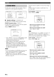
... ) or larger: large Woofer section of the front speakers connected to the front left and right speakers. 48 En The center channel signals are small Select "SMALL" (small). A)SPEAKER SET B)SP LEVEL C)SP DISTANCE D)CENTER GEQ E)LFE LEVEL [ ]/[ ]:Up/Down [ENTER]:Enter ;MANUAL SETUP 1 SOUND MENU 2/2 . When the front speakers are directed to the FRONT B terminals. Note When "LFE/BASS OUT" is large Select "LRG" (large). Woofer section of a speaker is 16 cm (6.5 in another zone.
... ) or larger: large Woofer section of the front speakers connected to the front left and right speakers. 48 En The center channel signals are small Select "SMALL" (small). A)SPEAKER SET B)SP LEVEL C)SP DISTANCE D)CENTER GEQ E)LFE LEVEL [ ]/[ ]:Up/Down [ENTER]:Enter ;MANUAL SETUP 1 SOUND MENU 2/2 . When the front speakers are directed to the FRONT B terminals. Note When "LFE/BASS OUT" is large Select "LRG" (large). Woofer section of a speaker is 16 cm (6.5 in another zone.

Owner's Manual
Page 55
... mute function reduces the output volume (see page 49), some signals may be necessary when using certain LCD monitors or projectors. Control range: -6.0 to +6.0 dB Control step: 0.5 dB Initial setting: 0 dB SET MENU ■ Dynamic range F)D.RANGE Use this feature to adjust the output level of the LFE (lowfrequency effect) channel according to the currently selected source component or a test tone. Note Depending on the settings of dynamic range compression to be output at low volume levels. • Select "STD" (standard) for "CENTER...
... mute function reduces the output volume (see page 49), some signals may be necessary when using certain LCD monitors or projectors. Control range: -6.0 to +6.0 dB Control step: 0.5 dB Initial setting: 0 dB SET MENU ■ Dynamic range F)D.RANGE Use this feature to adjust the output level of the LFE (lowfrequency effect) channel according to the currently selected source component or a test tone. Note Depending on the settings of dynamic range compression to be output at low volume levels. • Select "STD" (standard) for "CENTER...

Owner's Manual
Page 58
... input source. p p p p SET MENU ■ Multi channel input setup E)MULTI CH SET 2 INPUT MENU E)MULTI CH SET BGV;;;;;;;;;LAST [p]/[[]:Select Background Video BGV Use this feature to adjust the optional system parameters. ;MANUAL SETUP 3 OPTION MENU . Choices: DVD, DTV/CBL, V-AUX, DVR, LAST y Select "LAST" to set whether to turn off the OSD 30 seconds after you perform a certain operation. INI E)USB PLAY STYLE [ ]/[ ]:Up/Down [ENTER]:Enter ■ Display settings A)DISPLAY SET 3 OPTION MENU A)DISPLAY SET . Front panel display scroll FL SCROLL Use this feature to set this menu...
... input source. p p p p SET MENU ■ Multi channel input setup E)MULTI CH SET 2 INPUT MENU E)MULTI CH SET BGV;;;;;;;;;LAST [p]/[[]:Select Background Video BGV Use this feature to adjust the optional system parameters. ;MANUAL SETUP 3 OPTION MENU . Choices: DVD, DTV/CBL, V-AUX, DVR, LAST y Select "LAST" to set whether to turn off the OSD 30 seconds after you perform a certain operation. INI E)USB PLAY STYLE [ ]/[ ]:Up/Down [ENTER]:Enter ■ Display settings A)DISPLAY SET 3 OPTION MENU A)DISPLAY SET . Front panel display scroll FL SCROLL Use this feature to set this menu...
Owner's Manual
Page 65
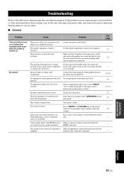
... speaker wire connections on this unit. manual of the connected component is turned on. HDMI connection. No sound The power cable is not connected or the plug is incorrect. The volume is muted. The sound is turned down. Audio signals input at the HDMI jack are Make an analog or digital connection beside the not output from a source component, such as lightning or strong static electricity). The protection circuitry has been activated. Set this unit does not function properly. Secure the connections...
... speaker wire connections on this unit. manual of the connected component is turned on. HDMI connection. No sound The power cable is not connected or the plug is incorrect. The volume is muted. The sound is turned down. Audio signals input at the HDMI jack are Make an analog or digital connection beside the not output from a source component, such as lightning or strong static electricity). The protection circuitry has been activated. Set this unit does not function properly. Secure the connections...
Owner's Manual
Page 67
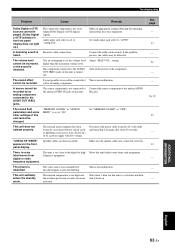
... turn it in the front panel display does not light up.) The connected component is not set the volume level Adjust "MAX VOL." Set Audio input jack select to "OFF". higher than the maximum volume level. with low voltage. The sound field parameters and some other settings of the component. "CHECK SP WIRES" appears in "OPTION MENU" is too close to output Dolby Digital or DTS digital signals. There is not malfunction. This unit suddenly enters the standby mode. Connect the audio cables firmly. setting...
... turn it in the front panel display does not light up.) The connected component is not set the volume level Adjust "MAX VOL." Set Audio input jack select to "OFF". higher than the maximum volume level. with low voltage. The sound field parameters and some other settings of the component. "CHECK SP WIRES" appears in "OPTION MENU" is too close to output Dolby Digital or DTS digital signals. There is not malfunction. This unit suddenly enters the standby mode. Connect the audio cables firmly. setting...

Owner's Manual
Page 69
... an error message "E-6" occurs repeatedly, please contact a qualified Yamaha service center. If "SWFR:TOO LOUD" or "SWFR:TOO LOW" appears, adjust the output volume of similar quality. ADDITIONAL INFORMATION English 65 En A surround channel signal is out of adjustable range. The "AUTO SETUP" procedure was unplugged during the "AUTO SETUP" procedure. Connect the supplied optimizer microphone to OPTIMIZER MIC jack on the speakers even when the speakers are made .) Check the speaker connections for proper...
... an error message "E-6" occurs repeatedly, please contact a qualified Yamaha service center. If "SWFR:TOO LOUD" or "SWFR:TOO LOW" appears, adjust the output volume of similar quality. ADDITIONAL INFORMATION English 65 En A surround channel signal is out of adjustable range. The "AUTO SETUP" procedure was unplugged during the "AUTO SETUP" procedure. Connect the supplied optimizer microphone to OPTIMIZER MIC jack on the speakers even when the speakers are made .) Check the speaker connections for proper...
Owner's Manual
Page 71
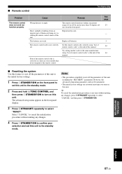
... 1STANDBY/ON to the standby mode. The advanced setup menu appears in the front panel display. However, the advanced setup menu parameters will not be initialized. • The initial factory settings are weak. Replace all the parameters of remote control codes" at any time without making any changes. 4 Press 1STANDBY/ON to confirm your selection and set , there are some models that do not respond to select "RESET". See page 23...
... 1STANDBY/ON to the standby mode. The advanced setup menu appears in the front panel display. However, the advanced setup menu parameters will not be initialized. • The initial factory settings are weak. Replace all the parameters of remote control codes" at any time without making any changes. 4 Press 1STANDBY/ON to confirm your selection and set , there are some models that do not respond to select "RESET". See page 23...
Owner's Manual
Page 75
...DISPLAY SET, Option menu ......... 54 A)INPUT ASSIGNMENT, Input menu 52 A)SPEAKER SET, Sound menu ......... 48 A.DELAY, Audio settings 51 AC OUTLETS (SWITCHED 21 AC OUTLETS, Rear panel 10 AM antenna, Connection 20 AM tuning 40 Amplifier function OSD display time, Display settings 54 Audio components, Connection 19 Audio delay, Audio settings 51 AUDIO jacks 14 Audio jacks 14 AUDIO jacks, Rear panel 10 AUDIO SELECT 33 Audio select, Option menu 55 Audio settings, Sound menu 51 AUTO SETUP 24 AUTO SETUP, Error message 64 AUTO: RESULT display, Auto setup 26 Automatic preset tuning...
...DISPLAY SET, Option menu ......... 54 A)INPUT ASSIGNMENT, Input menu 52 A)SPEAKER SET, Sound menu ......... 48 A.DELAY, Audio settings 51 AC OUTLETS (SWITCHED 21 AC OUTLETS, Rear panel 10 AM antenna, Connection 20 AM tuning 40 Amplifier function OSD display time, Display settings 54 Audio components, Connection 19 Audio delay, Audio settings 51 AUDIO jacks 14 Audio jacks 14 AUDIO jacks, Rear panel 10 AUDIO SELECT 33 Audio select, Option menu 55 Audio settings, Sound menu 51 AUTO SETUP 24 AUTO SETUP, Error message 64 AUTO: RESULT display, Auto setup 26 Automatic preset tuning...
Owner's Manual
Page 76
...LFE/BASS OUT, Speaker settings ...... 49 LFE/Bass out, Speaker settings 49 Low-frequency effect level, Sound menu 51 LVL 25 LVL, Auto setup result 25 ■M Manual preset tuning, FM/AM tuning 41 MANUAL SETUP, SET MENU ......... 46 Manual setup, SET MENU 46 Manual tuning, FM/AM tuning 40 MAX VOL., Audio settings 52 Maximum volume, Audio settings ....... 52 MD recorder, Connection 19 Memory guard, Option menu 55 Movie Dramatic 37 Movie Spacious 37 MULTI CH INPUT jacks, Connection 19 MULTI CH INPUT jacks, Rear panel 10 Multi channel input setup, Input menu 54 Multi-channel source...
...LFE/BASS OUT, Speaker settings ...... 49 LFE/Bass out, Speaker settings 49 Low-frequency effect level, Sound menu 51 LVL 25 LVL, Auto setup result 25 ■M Manual preset tuning, FM/AM tuning 41 MANUAL SETUP, SET MENU ......... 46 Manual setup, SET MENU 46 Manual tuning, FM/AM tuning 40 MAX VOL., Audio settings 52 Maximum volume, Audio settings ....... 52 MD recorder, Connection 19 Memory guard, Option menu 55 Movie Dramatic 37 Movie Spacious 37 MULTI CH INPUT jacks, Connection 19 MULTI CH INPUT jacks, Rear panel 10 Multi channel input setup, Input menu 54 Multi-channel source...

Owner's Manual
Page 77
... audio player using ..... 43 USB playback operation 43 USB playback styles 55 USB, Troubleshooting 66 ■V VIDEO AUX jacks, Front panel .......... 20 Video components, Connection 16 VIDEO jacks 14 Video jacks 14 VIDEO jacks, Rear panel 10 Video monitor, Connection 16 Virtual CINEMA DSP 38 VIRTUAL indicator, Front panel display 22 VOLUME level indicator, Front panel display 22 Volume Trim, Input menu 53 ■W W-1:OUT OF PHASE, Auto setup error message 65 W-2:DISTANCE ERROR, Auto setup error message 65 W-3:LEVEL ERROR, Auto setup error message 65 WIRING/LEVEL 25 WIRING...
... audio player using ..... 43 USB playback operation 43 USB playback styles 55 USB, Troubleshooting 66 ■V VIDEO AUX jacks, Front panel .......... 20 Video components, Connection 16 VIDEO jacks 14 Video jacks 14 VIDEO jacks, Rear panel 10 Video monitor, Connection 16 Virtual CINEMA DSP 38 VIRTUAL indicator, Front panel display 22 VOLUME level indicator, Front panel display 22 Volume Trim, Input menu 53 ■W W-1:OUT OF PHASE, Auto setup error message 65 W-2:DISTANCE ERROR, Auto setup error message 65 W-3:LEVEL ERROR, Auto setup error message 65 WIRING/LEVEL 25 WIRING...


