
Owners Manual
Page 2
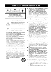
...cords at plugs, convenience receptacles, and the point where they may expose you to qualified service personnel under the following conditions: a) When the power-supply cord or plug is operated. 2 Retain Instructions - Quick stops, excessive force, and uneven surfaces may be retained for future reference. 3...use this can fall , causing serious injury to a child or adult, and serious damage to replace your product dealer or local power company. in the cabinet are not sure of the type of the product should follow the manufacturer's instructions, and should use instructions ...
...cords at plugs, convenience receptacles, and the point where they may expose you to qualified service personnel under the following conditions: a) When the power-supply cord or plug is operated. 2 Retain Instructions - Quick stops, excessive force, and uneven surfaces may be retained for future reference. 3...use this can fall , causing serious injury to a child or adult, and serious damage to replace your product dealer or local power company. in the cabinet are not sure of the type of the product should follow the manufacturer's instructions, and should use instructions ...
Owners Manual
Page 3
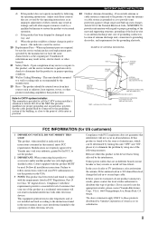
... this product is in proper operating condition. 22 Wall or Ceiling Mounting - The product should be used replacement parts specified by Yamaha may result in fire, electric shock, or other electronic devices. Modifications not expressly approved by the manufacturer or have the same ...ELECTRICAL CODE ANTENNA LEAD IN WIRE ANTENNA DISCHARGE UNIT (NEC SECTION 810-20) GROUNDING CONDUCTORS (NEC SECTION 810-21) GROUND CLAMPS POWER SERVICE GROUNDING ELECTRODE SYSTEM (NEC ART 250. Adjust only those products distributed by following measures: Relocate either this product, ask the...
... this product is in proper operating condition. 22 Wall or Ceiling Mounting - The product should be used replacement parts specified by Yamaha may result in fire, electric shock, or other electronic devices. Modifications not expressly approved by the manufacturer or have the same ...ELECTRICAL CODE ANTENNA LEAD IN WIRE ANTENNA DISCHARGE UNIT (NEC SECTION 810-20) GROUNDING CONDUCTORS (NEC SECTION 810-21) GROUND CLAMPS POWER SERVICE GROUNDING ELECTRODE SYSTEM (NEC ART 250. Adjust only those products distributed by following measures: Relocate either this product, ask the...
Owners Manual
Page 4
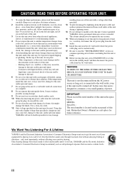
... through loud and clear without affecting your equipment by lightning, keep the power cable and outdoor antennas disconnected from the wall outlet, grasp the plug; Burning objects (i.e. Contact qualified YAMAHA service personnel when any damage resulting from other than specified is needed. ... Group recommend you to liquid dripping or splashing. YAMAHA will not be exposed to get the most importantly, without annoying blaring or distortion - On the top of this unit with high humidity (i.e. vacation), disconnect the AC power plug from excessive volume levels. do not place:...
... through loud and clear without affecting your equipment by lightning, keep the power cable and outdoor antennas disconnected from the wall outlet, grasp the plug; Burning objects (i.e. Contact qualified YAMAHA service personnel when any damage resulting from other than specified is needed. ... Group recommend you to liquid dripping or splashing. YAMAHA will not be exposed to get the most importantly, without annoying blaring or distortion - On the top of this unit with high humidity (i.e. vacation), disconnect the AC power plug from excessive volume levels. do not place:...
Owners Manual
Page 5
... player or an external decoder 21 Connecting a game console, a video camera or a portable audio player........... 21 Connecting the FM and AM antennas 22 Connecting the power cable 23 Turning on this unit or setting it to the standby mode 24 BASIC SETUP 25 BASIC OPERATION PLAYBACK 28 USING OTHER FEATURES 30...
... player or an external decoder 21 Connecting a game console, a video camera or a portable audio player........... 21 Connecting the FM and AM antennas 22 Connecting the power cable 23 Turning on this unit or setting it to the standby mode 24 BASIC SETUP 25 BASIC OPERATION PLAYBACK 28 USING OTHER FEATURES 30...
Owners Manual
Page 6
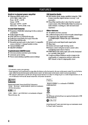
... of Digital Theater Systems, Inc. The XM name and related logos are registered trademarks of YAMAHA CORPORATION. "SILENT CINEMA" is a trademark of XM Satellite Radio Inc. FEATURES FEATURES Built-in 6-channel power amplifier ◆ Minimum RMS output power (0.9% THD, 1 kHz, 6 Ω) Front: 120 W + 120 W Center: 120 W Surround: 120 W + 120 W Subwoofer: 120 W (30 Hz...
... of Digital Theater Systems, Inc. The XM name and related logos are registered trademarks of YAMAHA CORPORATION. "SILENT CINEMA" is a trademark of XM Satellite Radio Inc. FEATURES FEATURES Built-in 6-channel power amplifier ◆ Minimum RMS output power (0.9% THD, 1 kHz, 6 Ω) Front: 120 W + 120 W Center: 120 W Surround: 120 W + 120 W Subwoofer: 120 W (30 Hz...
Owners Manual
Page 7
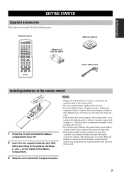
... one. • Do not use different types of batteries (such as these different types of batteries may be cleared. GETTING STARTED Remote control POWER POWER TV AV STANDBY POWER CD MD/CD-R TUNER XM DVD DTV/CBL DVR V-AUX REC DISC SKIP CODE SET MULTI CH IN SLEEP AMP TV VOL CH VOLUME...
... one. • Do not use different types of batteries (such as these different types of batteries may be cleared. GETTING STARTED Remote control POWER POWER TV AV STANDBY POWER CD MD/CD-R TUNER XM DVD DTV/CBL DVR V-AUX REC DISC SKIP CODE SET MULTI CH IN SLEEP AMP TV VOL CH VOLUME...
Owners Manual
Page 8
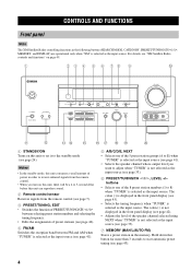
... page 45). • Selects the tuning frequency when "TUNER" is not displayed in the front panel display (see page 42). • Adjusts the level of power in order to receive infrared signals from the remote control. • When you want to 8) when "TUNER" is selected as the input source.
... page 45). • Selects the tuning frequency when "TUNER" is not displayed in the front panel display (see page 42). • Adjusts the level of power in order to receive infrared signals from the remote control. • When you want to 8) when "TUNER" is selected as the input source.
Owners Manual
Page 10
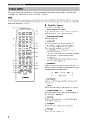
... the set up remote control codes (see page 83). 4 Sound field program selector buttons Select sound field programs (see page 38). - POWER POWER TV AV STANDBY POWER 0 A 1 Infrared signal transmitter Outputs infrared control signals. RETURN XM MEMORY PRESET/CH A-E/CAT. Use DIRECT ST. CONTROLS AND FUNCTIONS Remote.... LEVEL TITLE BAND SET MENU MENU SRCH MODE ENTER A-E/CAT. For details, see "REMOTE CONTROL FEATURES" on the rear panel. A POWER Turns on page 49. ■ Controlling this unit 1 Press AMP to control this transmitter at the component you want to control this ...
... the set up remote control codes (see page 83). 4 Sound field program selector buttons Select sound field programs (see page 38). - POWER POWER TV AV STANDBY POWER 0 A 1 Infrared signal transmitter Outputs infrared control signals. RETURN XM MEMORY PRESET/CH A-E/CAT. Use DIRECT ST. CONTROLS AND FUNCTIONS Remote.... LEVEL TITLE BAND SET MENU MENU SRCH MODE ENTER A-E/CAT. For details, see "REMOTE CONTROL FEATURES" on the rear panel. A POWER Turns on page 49. ■ Controlling this unit 1 Press AMP to control this transmitter at the component you want to control this ...
Owners Manual
Page 14
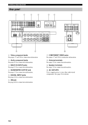
See page 23 for connection information. 0 AC OUTLETS Use to supply power to your other audiovisual components. CONTROLS AND FUNCTIONS Rear panel 1 2 3 4 56 AUDIO AUDIO MULTI CH INPUT CENTER OUTPUT DIGITAL INPUT XM DVD DTV/CBL DVD ...
See page 23 for connection information. 0 AC OUTLETS Use to supply power to your other audiovisual components. CONTROLS AND FUNCTIONS Rear panel 1 2 3 4 56 AUDIO AUDIO MULTI CH INPUT CENTER OUTPUT DIGITAL INPUT XM DVD DTV/CBL DVD ...
Owners Manual
Page 21
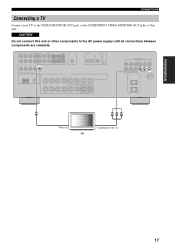
VIDEO MONITOR OUT COMPONENT VIDEO Y PB PR MONITOR OUT V Y PB PR Video in Component video in TV 17 CAUTION Do not connect this unit. PREPARATION CONNECTIONS Connecting a TV Connect your TV to the VIDEO MONITOR OUT jack, or the COMPONENT VIDEO MONITOR OUT jacks of this unit or other components to the AC power supply until all connections between components are complete.
VIDEO MONITOR OUT COMPONENT VIDEO Y PB PR MONITOR OUT V Y PB PR Video in Component video in TV 17 CAUTION Do not connect this unit. PREPARATION CONNECTIONS Connecting a TV Connect your TV to the VIDEO MONITOR OUT jack, or the COMPONENT VIDEO MONITOR OUT jacks of this unit or other components to the AC power supply until all connections between components are complete.
Owners Manual
Page 22
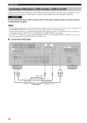
... example, if you connect your DVD player to both the DIGITAL INPUT (OPTICAL) and the DIGITAL INPUT (COAXIAL) jacks, priority is given to the AC power supply until all connections between components are examples of the STB. CAUTION Do not connect this unit, connect your other components to the signals input...
... example, if you connect your DVD player to both the DIGITAL INPUT (OPTICAL) and the DIGITAL INPUT (COAXIAL) jacks, priority is given to the AC power supply until all connections between components are examples of the STB. CAUTION Do not connect this unit, connect your other components to the signals input...
Owners Manual
Page 24
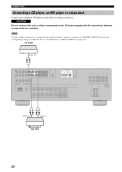
... Audio out Audio in "INPUT ASSIGN" (see page 78). CAUTION Do not connect this unit or other than the default component assigned to the AC power supply until all connections between components are complete. CONNECTIONS Connecting a CD player, an MD player or a tape deck Connect your CD player, MD player or...
... Audio out Audio in "INPUT ASSIGN" (see page 78). CAUTION Do not connect this unit or other than the default component assigned to the AC power supply until all connections between components are complete. CONNECTIONS Connecting a CD player, an MD player or a tape deck Connect your CD player, MD player or...
Owners Manual
Page 25
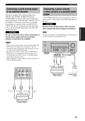
..., and you connect at the MULTI CH INPUT jacks to this unit or other components before using this unit and other components to the AC power supply until all connections between components are output only from a multi-format player, external decoder, sound processor or pre-amplifier. Note The audio signals input...
..., and you connect at the MULTI CH INPUT jacks to this unit or other components before using this unit and other components to the AC power supply until all connections between components are output only from a multi-format player, external decoder, sound processor or pre-amplifier. Note The audio signals input...
Owners Manual
Page 27
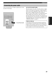
...AC wall outlet CONNECTIONS AC OUTLETS (SWITCHED) This unit equips 2 AC outlets. For information on the maximum power or the total power consumption of this unit is disconnected from the AC wall outlet or if the power supply is cut off when this unit is in the standby mode or the... that can be lost even if this unit is turned on page 93. Power to these outlets, see "SPECIFICATIONS" on . However, power to these outlets is disconnected from the AC wall outlet. PREPARATION 23 Connect the power cable of your other components to these outlets. Memory back-up The memory ...
...AC wall outlet CONNECTIONS AC OUTLETS (SWITCHED) This unit equips 2 AC outlets. For information on the maximum power or the total power consumption of this unit is disconnected from the AC wall outlet or if the power supply is cut off when this unit is in the standby mode or the... that can be lost even if this unit is turned on page 93. Power to these outlets, see "SPECIFICATIONS" on . However, power to these outlets is disconnected from the AC wall outlet. PREPARATION 23 Connect the power cable of your other components to these outlets. Memory back-up The memory ...
Owners Manual
Page 28
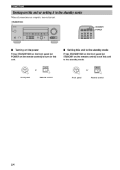
... l PRESET/TUNING/CH h LEVEL INPUT MODE MEMORY MAN'L/AUTO FM TUNING MODE DISPLAY AUTO/MAN'L INPUT MULTI CH INPUT VOLUME VIDEO AUX VIDEO L AUDIO R PORTABLE POWER POWER TV AV STANDBY POWER CD MD/CD-R TUNER XM DVD DTV/CBL DVR V-AUX REC CODE SET MULTI CH IN STANDBY... POWER ■ Turning on the power Press STANDBY/ON on the front panel (or POWER on this unit to turn on the remote control) to the standby mode. STANDBY /ON POWER or Front panel Remote control ■ Setting this unit to the...
... l PRESET/TUNING/CH h LEVEL INPUT MODE MEMORY MAN'L/AUTO FM TUNING MODE DISPLAY AUTO/MAN'L INPUT MULTI CH INPUT VOLUME VIDEO AUX VIDEO L AUDIO R PORTABLE POWER POWER TV AV STANDBY POWER CD MD/CD-R TUNER XM DVD DTV/CBL DVR V-AUX REC CODE SET MULTI CH IN STANDBY... POWER ■ Turning on the power Press STANDBY/ON on the front panel (or POWER on this unit to turn on the remote control) to the standby mode. STANDBY /ON POWER or Front panel Remote control ■ Setting this unit to the...
Owners Manual
Page 44
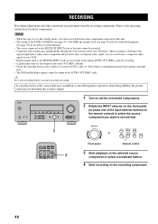
... Satellite Radio signals cannot be output at the AUDIO OUT (REC) jacks. INPUT 2 CD MD/CD-R TUNER or DVD DTV/CBL DVR V-AUX POWER POWER TV AV STANDBY POWER CD MD/CD-R TUNER XM DVD DTV/CBL DVR V-AUX REC CODE SET MULTI CH IN 2 Front panel Remote control 3 Start playback on the...
... Satellite Radio signals cannot be output at the AUDIO OUT (REC) jacks. INPUT 2 CD MD/CD-R TUNER or DVD DTV/CBL DVR V-AUX POWER POWER TV AV STANDBY POWER CD MD/CD-R TUNER XM DVD DTV/CBL DVR V-AUX REC CODE SET MULTI CH IN 2 Front panel Remote control 3 Start playback on the...

Owners Manual
Page 53
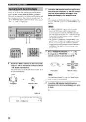
... selected category. Rotate the INPUT selector on the front panel (or press XM on the remote control) to select "XM" as the input source. POWER POWER TV AV STANDBY POWER CD MD/CD-R TUNER XM DVD DTV/CBL DVR V-AUX REC DISC SKIP CODE SET MULTI CH IN SLEEP 2 1 3 4 STEREO 1 MUSIC ENTERTAIN MOVIE...
... selected category. Rotate the INPUT selector on the front panel (or press XM on the remote control) to select "XM" as the input source. POWER POWER TV AV STANDBY POWER CD MD/CD-R TUNER XM DVD DTV/CBL DVR V-AUX REC DISC SKIP CODE SET MULTI CH IN SLEEP 2 1 3 4 STEREO 1 MUSIC ENTERTAIN MOVIE...
Owners Manual
Page 54
.../CH h LEVEL INPUT MODE MEMORY MAN'L/AUTO FM TUNING MODE DISPLAY AUTO/MAN'L INPUT MULTI CH INPUT VOLUME VIDEO AUX VIDEO L AUDIO R PORTABLE 31 POWER POWER TV AV STANDBY POWER CD MD/CD-R TUNER XM DVD DTV/CBL DVR V-AUX REC CODE SET MULTI CH IN 1 5 SPEAKERS 9 6 ENHANCER 0 7 8 NIGHT STRAIGHT 10 ENT. See...
.../CH h LEVEL INPUT MODE MEMORY MAN'L/AUTO FM TUNING MODE DISPLAY AUTO/MAN'L INPUT MULTI CH INPUT VOLUME VIDEO AUX VIDEO L AUDIO R PORTABLE 31 POWER POWER TV AV STANDBY POWER CD MD/CD-R TUNER XM DVD DTV/CBL DVR V-AUX REC CODE SET MULTI CH IN 1 5 SPEAKERS 9 6 ENHANCER 0 7 8 NIGHT STRAIGHT 10 ENT. See...
Owners Manual
Page 55
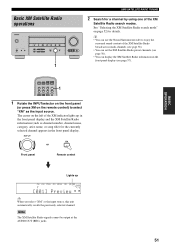
.... y • You can use the Neural Surround decoder to select "XM" as the input source, this unit automatically recalls the previously selected channel. POWER POWER TV AV STANDBY POWER CD MD/CD-R TUNER XM DVD DTV/CBL DVR V-AUX REC CODE SET MULTI CH IN 1 1 Rotate the INPUTselector on the front panel (or...
.... y • You can use the Neural Surround decoder to select "XM" as the input source, this unit automatically recalls the previously selected channel. POWER POWER TV AV STANDBY POWER CD MD/CD-R TUNER XM DVD DTV/CBL DVR V-AUX REC CODE SET MULTI CH IN 1 1 Rotate the INPUTselector on the front panel (or...
Owners Manual
Page 56
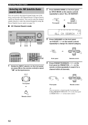
...-R TUNER CD pXM VOLUME dB CH SEARCH L R 3 Press CATEGORY on the remote control) repeatedly to change the channel category. A/B/C/D/E CATEGORY NEXT or Front panel A-E/CAT. POWER POWER TV AV STANDBY POWER CD MD/CD-R TUNER XM DVD DTV/CBL DVR V-AUX REC CODE SET MULTI CH IN 1 5 SPEAKERS 9 6 ENHANCER 0 7 8 NIGHT STRAIGHT 10 ENT.
...-R TUNER CD pXM VOLUME dB CH SEARCH L R 3 Press CATEGORY on the remote control) repeatedly to change the channel category. A/B/C/D/E CATEGORY NEXT or Front panel A-E/CAT. POWER POWER TV AV STANDBY POWER CD MD/CD-R TUNER XM DVD DTV/CBL DVR V-AUX REC CODE SET MULTI CH IN 1 5 SPEAKERS 9 6 ENHANCER 0 7 8 NIGHT STRAIGHT 10 ENT.


