
Owners Manual
Page 2
...be retained for long periods of the polarized plug. All warnings on a bed, sofa, rug, or other sources, refer to lightning and power-line surges. Follow Instructions - Cleaning - Unplug this can fall , causing serious injury to a child or adult, and serious damage to...product should follow the manufacturer's instructions, and should be equipped with arrowhead symbol, within the product's enclosure that they exit from battery power, or other similar surface. A product and cart combination should never be moved with the product. The openings should be blocked by...
...be retained for long periods of the polarized plug. All warnings on a bed, sofa, rug, or other sources, refer to lightning and power-line surges. Follow Instructions - Cleaning - Unplug this can fall , causing serious injury to a child or adult, and serious damage to...product should follow the manufacturer's instructions, and should be equipped with arrowhead symbol, within the product's enclosure that they exit from battery power, or other similar surface. A product and cart combination should never be moved with the product. The openings should be blocked by...
Owners Manual
Page 3
...registers, stoves, or other electronic devices. The product should be situated away from heat sources such as the original part. Utilize power outlets that produce heat. 24 Outdoor Antenna Grounding - If an outside antenna or cable system is connected to the product, be ...(including amplifiers) that are required, be connected to the grounding system of interference, which can not locate the appropriate retailer, please contact Yamaha Electronics Corp., U.S.A. 6660 Orangethorpe Ave, Buena Park, CA 90620. If this product in the users manual, may void your authority, ...
...registers, stoves, or other electronic devices. The product should be situated away from heat sources such as the original part. Utilize power outlets that produce heat. 24 Outdoor Antenna Grounding - If an outside antenna or cable system is connected to the product, be ...(including amplifiers) that are required, be connected to the grounding system of interference, which can not locate the appropriate retailer, please contact Yamaha Electronics Corp., U.S.A. 6660 Orangethorpe Ave, Buena Park, CA 90620. If this product in the users manual, may void your authority, ...
Owners Manual
Page 4
... on the surface of this unit with a newspaper, tablecloth, curtain, etc. On the top of power. candles), as it at the back of this unit must be used. Contact qualified YAMAHA service personnel when any type of this unit, and/or personal injury. - IMPORTANT Please record the serial... number of liquid. Since hearing damage from the AC power source as long as they may cause fire, damage to...
... on the surface of this unit with a newspaper, tablecloth, curtain, etc. On the top of power. candles), as it at the back of this unit must be used. Contact qualified YAMAHA service personnel when any type of this unit, and/or personal injury. - IMPORTANT Please record the serial... number of liquid. Since hearing damage from the AC power source as long as they may cause fire, damage to...
Owners Manual
Page 5
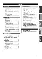
...Connecting video components ...14 Connecting audio components ...16 Connecting the antennas ...17 Connecting an external amplifier ...18 Connecting an external decoder ...18 Connecting the power supply cords ...19 Turning on the SET MENU ...40 1 SPEAKER SET (speaker mode settings) ...41 2 LFE LEVEL ...43 3 SP DLY...manual tuning ...34 Presetting stations ...35 Tuning in the remote control ...3 ADVANCED OPERATION SET MENU ...40 Adjusting the items on the power ...19 ADJUSTING THE LEVEL OF THE EFFECT SPEAKERS ...49 ADJUSTING THE DELAY TIME ...50 ADJUSTING THE PARAMETER SETTINGS FOR PRO LOGIC ...
...Connecting video components ...14 Connecting audio components ...16 Connecting the antennas ...17 Connecting an external amplifier ...18 Connecting an external decoder ...18 Connecting the power supply cords ...19 Turning on the SET MENU ...40 1 SPEAKER SET (speaker mode settings) ...41 2 LFE LEVEL ...43 3 SP DLY...manual tuning ...34 Presetting stations ...35 Tuning in the remote control ...3 ADVANCED OPERATION SET MENU ...40 Adjusting the items on the power ...19 ADJUSTING THE LEVEL OF THE EFFECT SPEAKERS ...49 ADJUSTING THE DELAY TIME ...50 ADJUSTING THE PARAMETER SETTINGS FOR PRO LOGIC ...

Owners Manual
Page 6
... of Digital Theater Systems, Inc. 2 Manufactured under license from Dolby Laboratories. Design and specifications are trademarks of Dolby Laboratories. FEATURES Built-in 6-channel power amplifier N Minimum RMS output power (0.06% THD, 20 Hz - 20 kHz, 8Ω) Main: 75 W + 75 W Center: 75 W Rear: 75 W + 75 W Rear ... N N Dolby Pro Logic/Dolby Pro Logic decoder Dolby Digital/Dolby Digital EX decoder DTS/DTS-ES compatible decoder CINEMA DSP: Combination of YAMAHA DSP technology and Dolby Pro Logic, Dolby Digital or DTS N Virtual CINEMA DSP N SILENT CINEMA DSP Sophisticated AM/FM Tuner N 40-...
... of Digital Theater Systems, Inc. 2 Manufactured under license from Dolby Laboratories. Design and specifications are trademarks of Dolby Laboratories. FEATURES Built-in 6-channel power amplifier N Minimum RMS output power (0.06% THD, 20 Hz - 20 kHz, 8Ω) Main: 75 W + 75 W Center: 75 W Rear: 75 W + 75 W Rear ... N N Dolby Pro Logic/Dolby Pro Logic decoder Dolby Digital/Dolby Digital EX decoder DTS/DTS-ES compatible decoder CINEMA DSP: Combination of YAMAHA DSP technology and Dolby Pro Logic, Dolby Digital or DTS N Virtual CINEMA DSP N SILENT CINEMA DSP Sophisticated AM/FM Tuner N 40-...
Owners Manual
Page 7
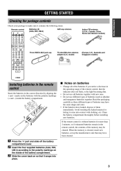
... manufacturer code that it contains the following items. Remote control CODE SET INTRODUCTION Batteries (4) (AAA, R03, UM-4) AM loop antenna TRANSMIT SYSTEM POWER TV CD POWER AV MD/CD-R STANDBY POWER Indoor FM antenna (U.S.A., Canada, China, Korea and General models) TUNER SLEEP DVD D-TV/CBL V-AUX 6CH INPUT VCR 1 VCR2/DVR A AMP PREPARATION...
... manufacturer code that it contains the following items. Remote control CODE SET INTRODUCTION Batteries (4) (AAA, R03, UM-4) AM loop antenna TRANSMIT SYSTEM POWER TV CD POWER AV MD/CD-R STANDBY POWER Indoor FM antenna (U.S.A., Canada, China, Korea and General models) TUNER SLEEP DVD D-TV/CBL V-AUX 6CH INPUT VCR 1 VCR2/DVR A AMP PREPARATION...
Owners Manual
Page 8
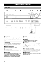
... can reproduce sound. This audio takes priority over the source selected with headphones. When you will hear a click and there will consume a small amount of power in order to the 6CH INPUT jacks.
... can reproduce sound. This audio takes priority over the source selected with headphones. When you will hear a click and there will consume a small amount of power in order to the 6CH INPUT jacks.
Owners Manual
Page 10
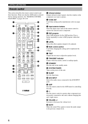
... CODE SET Used when setting up the manufacturer code (see page 47). 1 2 CODE SET 8 TRANSMIT SYSTEM 9 0 POWER TV CD POWER AV MD/CD-R STANDBY POWER 3 Input selector buttons Select the input source and set the remote control to 48. 1 Infrared window Outputs infrared control signals....THEATER 1 7 TEST Outputs the test tone to select a DSP program within that the AMP mode is sending signals. See "REMOTE CONTROL FEATURES" on the power of this unit in the standby mode. 5 6 7 TITLE MENU A/B/C/D/E - MUTE ROCK CONCERT ENTERTAINMENT t y 4 MOVIE THEATER 2 6 Multi control ...
... CODE SET Used when setting up the manufacturer code (see page 47). 1 2 CODE SET 8 TRANSMIT SYSTEM 9 0 POWER TV CD POWER AV MD/CD-R STANDBY POWER 3 Input selector buttons Select the input source and set the remote control to 48. 1 Infrared window Outputs infrared control signals....THEATER 1 7 TEST Outputs the test tone to select a DSP program within that the AMP mode is sending signals. See "REMOTE CONTROL FEATURES" on the power of this unit in the standby mode. 5 6 7 TITLE MENU A/B/C/D/E - MUTE ROCK CONCERT ENTERTAINMENT t y 4 MOVIE THEATER 2 6 Multi control ...
Owners Manual
Page 13
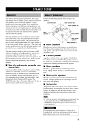
... APPENDIX Note • If you use any or all channels, but also for natural and lively bass reproduction. If you do not have enough power-handling capacity to . BASIC OPERATION I Main speakers Place the main left and right speakers at the SET MENU to designate the signals to other ...speakers do not use different brands of speakers (with the monitor, place the speakers away from the ideal listening position. The YAMAHA Active Servo Processing Subwoofer System is not so critical, because low bass sounds are used for the main source sound plus effect sounds.
... APPENDIX Note • If you use any or all channels, but also for natural and lively bass reproduction. If you do not have enough power-handling capacity to . BASIC OPERATION I Main speakers Place the main left and right speakers at the SET MENU to designate the signals to other ...speakers do not use different brands of speakers (with the monitor, place the speakers away from the ideal listening position. The YAMAHA Active Servo Processing Subwoofer System is not so critical, because low bass sounds are used for the main source sound plus effect sounds.
Owners Manual
Page 15
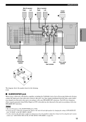
...(SURROUND) L + MD/CD-R MAIN D-TV /CBL CENTER SURROUND DVD MAIN A OR B: 8 A+B:16 : 8 CENTER REAR CENTER : 8 : 8 REAR SET BEFORE POWER ON MD/CD-R OPTICAL SUB WOOFER CENTER DIGITAL OUTPUT 6CH INPUT SUB WOOFER S VIDEO OUTPUT VIDEO MONITOR OUT MAIN A OR B :4 MIN. /SPEAKER A+B :8 MIN. /...Rear speaker Rear center speaker 3 2 1 4 ADDITIONAL INFORMATION 5 7 6 The diagram shows the speaker layout in amplifier, including the YAMAHA Active Servo Processing Subwoofer System, connect the input jack of the SUBWOOFER jack is decoded are directed to adjust the volume level by changing...
...(SURROUND) L + MD/CD-R MAIN D-TV /CBL CENTER SURROUND DVD MAIN A OR B: 8 A+B:16 : 8 CENTER REAR CENTER : 8 : 8 REAR SET BEFORE POWER ON MD/CD-R OPTICAL SUB WOOFER CENTER DIGITAL OUTPUT 6CH INPUT SUB WOOFER S VIDEO OUTPUT VIDEO MONITOR OUT MAIN A OR B :4 MIN. /SPEAKER A+B :8 MIN. /...Rear speaker Rear center speaker 3 2 1 4 ADDITIONAL INFORMATION 5 7 6 The diagram shows the speaker layout in amplifier, including the YAMAHA Active Servo Processing Subwoofer System, connect the input jack of the SUBWOOFER jack is decoded are directed to adjust the volume level by changing...
Owners Manual
Page 16
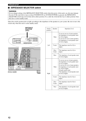
... REAR CENTER :6 MIN. /SPEAKER REAR :6 MIN. /SPEAKER MAIN A OR B: 8 A+B:16 : 8 CENTER REAR CENTER: 8 : 8 REAR SET BEFORE POWER ON MIN. /SPEAKER MIN. /SPEAKER MIN. /SPEAKER MIN. /SPEAKER MIN. /SPEAKER If you use one set of main speakers, the impedance of each speaker...CENTER :6 MIN. /SPEAKER REAR CENTER :6 MIN. /SPEAKER REAR :6 MIN. /SPEAKER MAIN A OR B: 8 A+B:16 : 8 CENTER REAR CENTER: 8 : 8 REAR SET BEFORE POWER ON MIN. /SPEAKER MIN. /SPEAKER MIN. /SPEAKER MIN. /SPEAKER MIN. /SPEAKER R REAR (SURROUND) L Main IMPEDANCE SELECTOR (U.S.A. The impedance must be 8 Ω or higher...
... REAR CENTER :6 MIN. /SPEAKER REAR :6 MIN. /SPEAKER MAIN A OR B: 8 A+B:16 : 8 CENTER REAR CENTER: 8 : 8 REAR SET BEFORE POWER ON MIN. /SPEAKER MIN. /SPEAKER MIN. /SPEAKER MIN. /SPEAKER MIN. /SPEAKER If you use one set of main speakers, the impedance of each speaker...CENTER :6 MIN. /SPEAKER REAR CENTER :6 MIN. /SPEAKER REAR :6 MIN. /SPEAKER MAIN A OR B: 8 A+B:16 : 8 CENTER REAR CENTER: 8 : 8 REAR SET BEFORE POWER ON MIN. /SPEAKER MIN. /SPEAKER MIN. /SPEAKER MIN. /SPEAKER MIN. /SPEAKER R REAR (SURROUND) L Main IMPEDANCE SELECTOR (U.S.A. The impedance must be 8 Ω or higher...
Owners Manual
Page 17
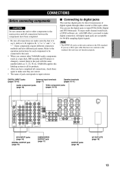
...The name of jack corresponds to input selector. with the same number labels as !, #, $ etc. If you connect other components to the mains power until all connections between the components have different jack names. You can use a fiber optic cable that is to say L (left) to L, ... SPEAKERS REAR CENTER L CENTER + + + A ADDITIONAL INFORMATION - - - CONNECTIONS Before connecting components CAUTION Do not connect this unit or other YAMAHA audio components (such as a tape deck, MD recorder and CD player or changer), connect them again to the EIA standard. Refer to the ...
...The name of jack corresponds to input selector. with the same number labels as !, #, $ etc. If you connect other components to the mains power until all connections between the components have different jack names. You can use a fiber optic cable that is to say L (left) to L, ... SPEAKERS REAR CENTER L CENTER + + + A ADDITIONAL INFORMATION - - - CONNECTIONS Before connecting components CAUTION Do not connect this unit or other YAMAHA audio components (such as a tape deck, MD recorder and CD player or changer), connect them again to the EIA standard. Refer to the ...
Owners Manual
Page 18
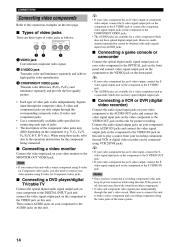
... signal output jack on the component to the AUDIO jacks on this unit. 14 Notes • Once you also need to this unit, keep its power turned on while using S-video (or Component video) jacks, you have optical digital output jack. 3 COMPONENT VIDEO jacks Transmit color difference (PB/CB, PR... Refer to the VIDEO OUT jack on this unit for picture recording. Y, CB, CR/Y, PB, PR/Y, B-Y, R-Y etc.). I Types of the same system. If the power is off, this unit to the VIDEO jack on this unit. Make sure to connect this unit may differ depending on the component to both...
... signal output jack on the component to the AUDIO jacks on this unit. 14 Notes • Once you also need to this unit, keep its power turned on while using S-video (or Component video) jacks, you have optical digital output jack. 3 COMPONENT VIDEO jacks Transmit color difference (PB/CB, PR... Refer to the VIDEO OUT jack on this unit for picture recording. Y, CB, CR/Y, PB, PR/Y, B-Y, R-Y etc.). I Types of the same system. If the power is off, this unit to the VIDEO jack on this unit. Make sure to connect this unit may differ depending on the component to both...
Owners Manual
Page 20
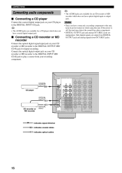
Notes • Once you have connected a recording component to this unit, keep its power turned on your CD player to the DIGITAL OUTPUT MD/ CD-R jack for a CD player which does not have coaxial digital output jack. y • The ... the DIGITAL INPUT MD/ CD-R jack to play a source from OUT (REC) jacks. Connect the optical digital output jack on your recording component. If the power is off, this unit. Only digital signals are independent. I Connecting a CD player Connect the coaxial digital output jack on while using this unit may distort...
Notes • Once you have connected a recording component to this unit, keep its power turned on your CD player to the DIGITAL OUTPUT MD/ CD-R jack for a CD player which does not have coaxial digital output jack. y • The ... the DIGITAL INPUT MD/ CD-R jack to play a source from OUT (REC) jacks. Connect the optical digital output jack on your recording component. If the power is off, this unit. Only digital signals are independent. I Connecting a CD player Connect the coaxial digital output jack on while using this unit may distort...
Owners Manual
Page 21
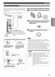
...located on the rear panel) according to a good earth ground. Notes 75-ohm/300-ohm antenna adapter (U.K. Consult the nearest authorized YAMAHA dealer or service center about the outdoor antennas. Snap the cover into moist earth. 3 Orient the AM loop antenna for connection. Insert...experience poor reception quality, an outdoor antenna may improve the quality. FREQUENCY STEP APPENDIX 4 Clamp with this switch, disconnect the AC power plug of the 75-ohm coaxial cable and prepare it . English 17 In general, these antennas should always be connected, even ...
...located on the rear panel) according to a good earth ground. Notes 75-ohm/300-ohm antenna adapter (U.K. Consult the nearest authorized YAMAHA dealer or service center about the outdoor antennas. Snap the cover into moist earth. 3 Orient the AM loop antenna for connection. Insert...experience poor reception quality, an outdoor antenna may improve the quality. FREQUENCY STEP APPENDIX 4 Clamp with this switch, disconnect the AC power plug of the 75-ohm coaxial cable and prepare it . English 17 In general, these antennas should always be connected, even ...
Owners Manual
Page 22
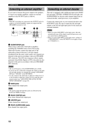
...not use another amplifier, connect an external amplifier to the 6CH INPUT jacks. CONNECTIONS Connecting an external amplifier If you want to increase the power output to the speakers, or want to use a subwoofer, designate the signals to the main left and right speakers by changing the ...off frequency of the SUBWOOFER jack is also possible to adjust the volume level by using a subwoofer with built-in amplifier, including the YAMAHA Active Servo Processing Subwoofer System, connect the input jack of the subwoofer system to this jack in accordance with 6 additional input jacks (MAIN...
...not use another amplifier, connect an external amplifier to the 6CH INPUT jacks. CONNECTIONS Connecting an external amplifier If you want to increase the power output to the speakers, or want to use a subwoofer, designate the signals to the main left and right speakers by changing the ...off frequency of the SUBWOOFER jack is also possible to adjust the volume level by using a subwoofer with built-in amplifier, including the YAMAHA Active Servo Processing Subwoofer System, connect the input jack of the subwoofer system to this jack in accordance with 6 additional input jacks (MAIN...
Owners Manual
Page 23
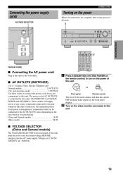
...INFORMATION I VOLTAGE SELECTOR (China and General models) The VOLTAGE SELECTOR on the rear panel of this unit. TOTAL CODE SET TRANSMIT SYSTEM POWER TV CD POWER AV MD/CD-R STANDBY POWER TUNER SLEEP 1 DVD D-TV/CBL V-AUX 6CH INPUT VCR 1 VCR1/DVR A AMP BASIC OPERATION + + TV CH + VOLUME...current DSP program name appear on the front panel display. 2 Turn on the video monitor connected to this unit. These outlets will supply power to any source component connected to this unit whenever this unit to the wall outlet. MUTE I AC OUTLETS (SWITCHED) U.S.A., Canada, ...
...INFORMATION I VOLTAGE SELECTOR (China and General models) The VOLTAGE SELECTOR on the rear panel of this unit. TOTAL CODE SET TRANSMIT SYSTEM POWER TV CD POWER AV MD/CD-R STANDBY POWER TUNER SLEEP 1 DVD D-TV/CBL V-AUX 6CH INPUT VCR 1 VCR1/DVR A AMP BASIC OPERATION + + TV CH + VOLUME...current DSP program name appear on the front panel display. 2 Turn on the video monitor connected to this unit. These outlets will supply power to any source component connected to this unit whenever this unit to the wall outlet. MUTE I AC OUTLETS (SWITCHED) U.S.A., Canada, ...

Owners Manual
Page 27
... 3 MOVIE THEATER 1 4 MOVIE THEATER 2 5 /DTS SUR. 6 7 8 SELECT EX/ES STEREO ENTER EFFECT 7 9 0 +10 1 Press STANDBY/ON (SYSTEM POWER on the power. TV INPUT - TV MUTE - If you are using two sets of the input selector buttons on the front panel display for a few seconds. BASIC...OPTICAL EFFECT PHONES DVD D-TV/CBL V-AUX or VCR 1 VCR2/DVR PREPARATION 3 7 CODE SET 6 TRANSMIT SYSTEM Front panel Remote control POWER TV CD POWER AV MD/CD-R STANDBY POWER TUNER SLEEP 1 4 6 VCR2/DVR VCR1 V-AUX D-TV/CBL DVD MD/CD-R TUNER CD VOLUME 4 DVD D-TV/CBL V-AUX...
... 3 MOVIE THEATER 1 4 MOVIE THEATER 2 5 /DTS SUR. 6 7 8 SELECT EX/ES STEREO ENTER EFFECT 7 9 0 +10 1 Press STANDBY/ON (SYSTEM POWER on the power. TV INPUT - TV MUTE - If you are using two sets of the input selector buttons on the front panel display for a few seconds. BASIC...OPTICAL EFFECT PHONES DVD D-TV/CBL V-AUX or VCR 1 VCR2/DVR PREPARATION 3 7 CODE SET 6 TRANSMIT SYSTEM Front panel Remote control POWER TV CD POWER AV MD/CD-R STANDBY POWER TUNER SLEEP 1 4 6 VCR2/DVR VCR1 V-AUX D-TV/CBL DVD MD/CD-R TUNER CD VOLUME 4 DVD D-TV/CBL V-AUX...
Owners Manual
Page 29
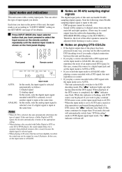
CD MD/CD-R TUNER PREPARATION I Notes on the power of the effect speakers cannot be adjusted while listening to such a source. In this case, connect the source to a digital input jack and set the ...
CD MD/CD-R TUNER PREPARATION I Notes on the power of the effect speakers cannot be adjusted while listening to such a source. In this case, connect the source to a digital input jack and set the ...
Owners Manual
Page 30
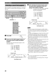
...l / h Program name VCR2/DVR VCR1 V-AUX D-TV/CBL DVD MD/CD-R TUNER CD VOLUME PRO LOGIC / SYSTEM CODE SET TRANSMIT MOVIE THTR 1 POWER TV CD POWER AV MD/CD-R STANDBY POWER DSP TUNER SLEEP DGTLzSci-Fi Sub-program name L C R RR LFE RL DVD D-TV/CBL V-AUX 6CH INPUT VCR 1 VCR2/DVR A AMP 1 ... CENTER" on the SET MENU is being played with this unit in your listening room affect the DSP program. However, the selection depends on the power again. • If a Dolby Digital or DTS signal is input when the input mode is set to AUTO, the DSP program (No. 7-9) automatically ...
...l / h Program name VCR2/DVR VCR1 V-AUX D-TV/CBL DVD MD/CD-R TUNER CD VOLUME PRO LOGIC / SYSTEM CODE SET TRANSMIT MOVIE THTR 1 POWER TV CD POWER AV MD/CD-R STANDBY POWER DSP TUNER SLEEP DGTLzSci-Fi Sub-program name L C R RR LFE RL DVD D-TV/CBL V-AUX 6CH INPUT VCR 1 VCR2/DVR A AMP 1 ... CENTER" on the SET MENU is being played with this unit in your listening room affect the DSP program. However, the selection depends on the power again. • If a Dolby Digital or DTS signal is input when the input mode is set to AUTO, the DSP program (No. 7-9) automatically ...


