
Owner's Manual
Page 10
... Operation 181 Creating a New Automix Recording 182 Recording the Automix Data 183 Automix Playback 185 Punch In and Out of media that you can use with the AW2400 ........266 MIDI data format 272 MIDI Implementation Chart 276 Specifications 277 Dimensions 279 Index 280 Block diagram 284 10 AW2400 Owner's Manual Digital Input/Output & Optional Card...
... Operation 181 Creating a New Automix Recording 182 Recording the Automix Data 183 Automix Playback 185 Punch In and Out of media that you can use with the AW2400 ........266 MIDI data format 272 MIDI Implementation Chart 276 Specifications 277 Dimensions 279 Index 280 Block diagram 284 10 AW2400 Owner's Manual Digital Input/Output & Optional Card...
Owner's Manual
Page 15
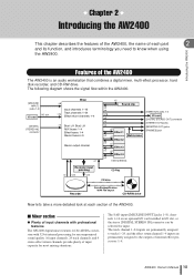
... permanently assigned to know when using the AW2400. AW2400 Owner's Manual 15 The 8 AD input ([MIC/LINE INPUT] jacks 1-8), channels 1-16 on an optional I/O card installed in I /O card [DIGITAL STEREO OUT] connector [STEREO OUT] jacks [MONITOR OUT] jacks [PHONES] jack Recorder input patching ×2 ×24 &#..., 24 track channels, and 4 stereo effect return channels provide plenty of input capacity for input. Introducing the AW2400 Features of the AW2400 The AW2400 is an audio workstation that combines a digital mixer, multi-effect processor, hard disk recorder, and CD-RW drive.
... permanently assigned to know when using the AW2400. AW2400 Owner's Manual 15 The 8 AD input ([MIC/LINE INPUT] jacks 1-8), channels 1-16 on an optional I/O card installed in I /O card [DIGITAL STEREO OUT] connector [STEREO OUT] jacks [MONITOR OUT] jacks [PHONES] jack Recorder input patching ×2 ×24 &#..., 24 track channels, and 4 stereo effect return channels provide plenty of input capacity for input. Introducing the AW2400 Features of the AW2400 The AW2400 is an audio workstation that combines a digital mixer, multi-effect processor, hard disk recorder, and CD-RW drive.
Owner's Manual
Page 18
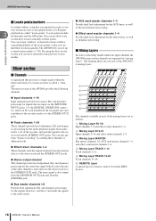
... Mixing Layer TRACK 13-24 Track channels 13-24. You can move instantly to the previous or next marker. The AW2400 lets you can also perform "bounce recording" by sending these locations quickly. You can find these channels to different tracks. ● Effect return channels...channels 1-24 These channels provide level adjustment, EQ, and dynamics processing for signals that are input via the [MIC/LINE INPUT] jacks 1-8, the [DIGITAL STEREO IN] connector, and/or an I/O card installed in /out or A-B repeat 2 playback are organized in "mixing layers". B Mixing Layer ...
... Mixing Layer TRACK 13-24 Track channels 13-24. You can move instantly to the previous or next marker. The AW2400 lets you can also perform "bounce recording" by sending these locations quickly. You can find these channels to different tracks. ● Effect return channels...channels 1-24 These channels provide level adjustment, EQ, and dynamics processing for signals that are input via the [MIC/LINE INPUT] jacks 1-8, the [DIGITAL STEREO IN] connector, and/or an I/O card installed in /out or A-B repeat 2 playback are organized in "mixing layers". B Mixing Layer ...

Owner's Manual
Page 21
...the indicator flashes only briefly on the highest peaks that will be encountered during the recording. F [UTILITY] key Press this key, includes settings for the unit's test tone oscillator, digital inputs and outputs, and other settings. C [INPUT SEL] keys 1-8 These keys select the mixer... input channel that will be recorded to the input of the rear panel MIC/LINE INPUT jacks 1-8 to be used for recording. Parts of the AW2400 and what they do ...
...the indicator flashes only briefly on the highest peaks that will be encountered during the recording. F [UTILITY] key Press this key, includes settings for the unit's test tone oscillator, digital inputs and outputs, and other settings. C [INPUT SEL] keys 1-8 These keys select the mixer... input channel that will be recorded to the input of the rear panel MIC/LINE INPUT jacks 1-8 to be used for recording. Parts of the AW2400 and what they do ...
Owner's Manual
Page 40
... the level meter goes into digital form with the highest possible quality before it is raised the level of the [GAIN] knob. 8 While playing the connected instrument, raise the [STEREO] fader to the IN 1-8 mixing layer. Refer to "Direct recording and Mixed recording" on the AW2400. Adjusting the input level 4... monitor system or headphones. When the POST FADER button is turned on the signal levels immediately following the fader are assigned to begin recording on page 49 for details. 7 Make sure that the corresponding input fader is lit, then raise the channel fader to the stereo...
... the level meter goes into digital form with the highest possible quality before it is raised the level of the [GAIN] knob. 8 While playing the connected instrument, raise the [STEREO] fader to the IN 1-8 mixing layer. Refer to "Direct recording and Mixed recording" on the AW2400. Adjusting the input level 4... monitor system or headphones. When the POST FADER button is turned on the signal levels immediately following the fader are assigned to begin recording on page 49 for details. 7 Make sure that the corresponding input fader is lit, then raise the channel fader to the stereo...
Owner's Manual
Page 51
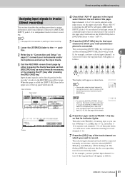
...field on the left side of the page. AW2400 Owner's Manual 51 HINT • See page 99 for more details on patching for direct recording. Direct recording and Mixed recording Assigning input signals to tracks (Direct recording) This section describes the patching procedure to assign instruments ...red. NOTE • To select the [DIGITAL STEREO IN] connector as the record source you have selected input channel 1 as your record source the top panel keys will need to assign the [DIGITAL STEREO IN] connector to the recorder's tracks via the DIGITAL IN field (1.2-15.16). and...
...field on the left side of the page. AW2400 Owner's Manual 51 HINT • See page 99 for more details on patching for direct recording. Direct recording and Mixed recording Assigning input signals to tracks (Direct recording) This section describes the patching procedure to assign instruments ...red. NOTE • To select the [DIGITAL STEREO IN] connector as the record source you have selected input channel 1 as your record source the top panel keys will need to assign the [DIGITAL STEREO IN] connector to the recorder's tracks via the DIGITAL IN field (1.2-15.16). and...
Owner's Manual
Page 54
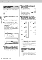
... details on the left side of the AW2400's stereo buses (Bus1 and Bus2), allowing mixed signals to be monitored via the DIGITAL IN field (1.2-15.16). NOTE • To select the [DIGITAL STEREO IN] connector as follows. Direct recording and Mixed recording Assigning input signals to tracks (Mixed recording) Use the following procedure to set...
... details on the left side of the AW2400's stereo buses (Bus1 and Bus2), allowing mixed signals to be monitored via the DIGITAL IN field (1.2-15.16). NOTE • To select the [DIGITAL STEREO IN] connector as follows. Direct recording and Mixed recording Assigning input signals to tracks (Mixed recording) Use the following procedure to set...
Owner's Manual
Page 75
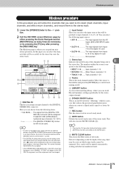
...connector to be assigned to an input channel, the clock of the external device and the AW2400 must be synchronized (→ p. 223). • The DIGITAL IN setting takes priority over the setting of the digital I ). This will also execute MUTE CLEAR (I /O card Not selected C Stereo bus ...Display section [SHIFT] key has the same effect as necessary, or by pressing the [F4] key after pressing the [RECORD] key. If you can choose from the [DIGITAL STEREO IN] connector will be displayed for "dithering," which some tracks cannot be assigned to the -∞ position. 2...
...connector to be assigned to an input channel, the clock of the external device and the AW2400 must be synchronized (→ p. 223). • The DIGITAL IN setting takes priority over the setting of the digital I ). This will also execute MUTE CLEAR (I /O card Not selected C Stereo bus ...Display section [SHIFT] key has the same effect as necessary, or by pressing the [F4] key after pressing the [RECORD] key. If you can choose from the [DIGITAL STEREO IN] connector will be displayed for "dithering," which some tracks cannot be assigned to the -∞ position. 2...

Owner's Manual
Page 77
...[ENTER] key. 8 HINT • Instead of the song, move the cursor to the [STEREO OUT] jacks or [DIGITAL STEREO OUT] connector. If the song is being output to cancel record-ready mode. The post-fader signal level will blink red. Then hold down the REC [●] key and press the... the [METER] key, then press the [F3] key. In this case, start playback on the AW2400 after it has been recorded as a stereo track, it cannot be recorded on . Mixdown and bounce operations AW2400 Owner's Manual 77 The METER screen Master page will be selected for burning to rewind the song. If...
...[ENTER] key. 8 HINT • Instead of the song, move the cursor to the [STEREO OUT] jacks or [DIGITAL STEREO OUT] connector. If the song is being output to cancel record-ready mode. The post-fader signal level will blink red. Then hold down the REC [●] key and press the... the [METER] key, then press the [F3] key. In this case, start playback on the AW2400 after it has been recorded as a stereo track, it cannot be recorded on . Mixdown and bounce operations AW2400 Owner's Manual 77 The METER screen Master page will be selected for burning to rewind the song. If...
Owner's Manual
Page 100
... selected input channel has already been assigned to the symbol for recording, there may be cancelled. lit flash Tr ack channels (Layer section [TRACK 1-12] key lit) 100 AW2400 Owner's Manual The DIGITAL IN setting takes priority over other inputs selected in which the signal...Assign the signal of an input channel or track channel is on, you selected input channel 1 as the recording destination. F DIRECT OUT Here you enable cascade connection, the digital audio signal received from which some tracks cannot be selected as follows. The corresponding [INPUT SEL] key (or...
... selected input channel has already been assigned to the symbol for recording, there may be cancelled. lit flash Tr ack channels (Layer section [TRACK 1-12] key lit) 100 AW2400 Owner's Manual The DIGITAL IN setting takes priority over other inputs selected in which the signal...Assign the signal of an input channel or track channel is on, you selected input channel 1 as the recording destination. F DIRECT OUT Here you enable cascade connection, the digital audio signal received from which some tracks cannot be selected as follows. The corresponding [INPUT SEL] key (or...
Owner's Manual
Page 102
... flow C D G H 1 Input Select Here you can assign the [DIGITAL STEREO IN] connector to select the send-destination for the signal of the song and on /off by pressing the [F2] key after pressing the [RECORD] key. C Tracks This area indicates the connection status of input channels 1-16. ... 2) to one of all input channel and track channel assignments will be cancelled. You can choose from the same inputs as in the RECORD screen Direct page. 102 AW2400 Owner's Manual F Bus 1, Bus 2 These four lines indicate the bus 1 L/R and bus 2 L/R signal routes. G MUTE CLEAR button ...
... flow C D G H 1 Input Select Here you can assign the [DIGITAL STEREO IN] connector to select the send-destination for the signal of the song and on /off by pressing the [F2] key after pressing the [RECORD] key. C Tracks This area indicates the connection status of input channels 1-16. ... 2) to one of all input channel and track channel assignments will be cancelled. You can choose from the same inputs as in the RECORD screen Direct page. 102 AW2400 Owner's Manual F Bus 1, Bus 2 These four lines indicate the bus 1 L/R and bus 2 L/R signal routes. G MUTE CLEAR button ...
Owner's Manual
Page 113
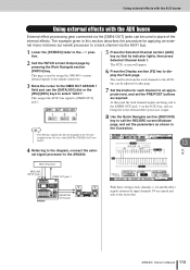
... assigned to an I/O card installed in place of the internal effects. This page is used in the I/O slot, or the [DIGITAL STEREO OUT] connector. 8 Use the Quick Navigate section [RECORD] key to the AW2400. The AUX1 screen will appear. 6 Press the Display section [F2] key to select "AUX1". Using external effects with the...
... assigned to an I/O card installed in place of the internal effects. This page is used in the I/O slot, or the [DIGITAL STEREO OUT] connector. 8 Use the Quick Navigate section [RECORD] key to the AW2400. The AUX1 screen will appear. 6 Press the Display section [F2] key to select "AUX1". Using external effects with the...
Owner's Manual
Page 137
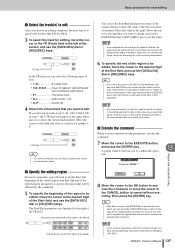
...; If you selected the sound clip as a result of executing a command, a track no longer contains any recorded data, the name of the region to be edited) 8 Move the cursor to the OK button to execute the...; CLIP Sound clip 4 Select the virtual track that you want to edit. Move the cursor to the digit that you want to change to "-NO REC-". NOTE • For some commands, you to confi...can press the [UNDO/REDO] key to return to the state prior to executing the command. tion. AW2400 Owner's Manual 137 In the same way as the value of the Start or End parameter. If necessary...
...; If you selected the sound clip as a result of executing a command, a track no longer contains any recorded data, the name of the region to be edited) 8 Move the cursor to the OK button to execute the...; CLIP Sound clip 4 Select the virtual track that you want to edit. Move the cursor to the digit that you want to change to "-NO REC-". NOTE • For some commands, you to confi...can press the [UNDO/REDO] key to return to the state prior to executing the command. tion. AW2400 Owner's Manual 137 In the same way as the value of the Start or End parameter. If necessary...
Owner's Manual
Page 143
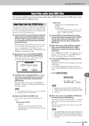
... appear in the UTILITY screen Preference page. 2 Move the cursor to the DISABLE setting each time you will change from DISABLE to ENABLE, and digital recording and importing from a CD will be read "Copyright Notice" (→ p. 7), and if you to select the desired editing command. NOTE &#...the "_" (underscore) character. 5 Call the EDIT screen Edit page by pressing the [F1] key after the AW2400 is a WAV file. 7 Press the [ENTER] key to prohibit digital recording from an external source or importing from the desired track of the second and later tracks) 15 NOTE •...
... appear in the UTILITY screen Preference page. 2 Move the cursor to the DISABLE setting each time you will change from DISABLE to ENABLE, and digital recording and importing from a CD will be read "Copyright Notice" (→ p. 7), and if you to select the desired editing command. NOTE &#...the "_" (underscore) character. 5 Call the EDIT screen Edit page by pressing the [F1] key after the AW2400 is a WAV file. 7 Press the [ENTER] key to prohibit digital recording from an external source or importing from the desired track of the second and later tracks) 15 NOTE •...
Owner's Manual
Page 199
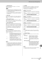
...When this button is ON MTC will be transmitted while the recorder is running. • MIDI CLOCK Button When this button is ON the MIDI clock will follow MTC received via the MIDI OUT/THRU connector (or USB connector or digital I /O card input port). If the incoming MTC has ...significant instability, synchronization may be transmitted while the recorder is always set to the same MMC device number. • When transmitting MMC data from the AW2400, the MMC device number is running. ...
...When this button is ON MTC will be transmitted while the recorder is running. • MIDI CLOCK Button When this button is ON the MIDI clock will follow MTC received via the MIDI OUT/THRU connector (or USB connector or digital I /O card input port). If the incoming MTC has ...significant instability, synchronization may be transmitted while the recorder is always set to the same MMC device number. • When transmitting MMC data from the AW2400, the MMC device number is running. ...
Owner's Manual
Page 210
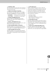
..., copy protection, and others. C NUDGE PLAY MODE Selects the playback method that is output from the DIGITAL STEREO OUT jack. Digital recording not possible 210 AW2400 Owner's Manual D NUDGE TIME Specifies the duration (Nudge Time) of digital audio data will be used by the Nudge function. When this page press the Work Navigate...
..., copy protection, and others. C NUDGE PLAY MODE Selects the playback method that is output from the DIGITAL STEREO OUT jack. Digital recording not possible 210 AW2400 Owner's Manual D NUDGE TIME Specifies the duration (Nudge Time) of digital audio data will be used by the Nudge function. When this page press the Work Navigate...
Owner's Manual
Page 211
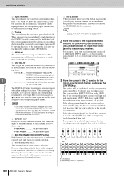
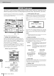
...from 0 to assign a name) will ask you for the corresponding parameter will be output together with the word clock source appears at a digital input on . • Recording is stopped. • Track editing is ended. • Import from the CD-RW drive is completed. • Import of a WAV ...an error message will be displayed when a signal that is and a popup window for confirmation when recalling a scene or library. AW2400 Preferences F POSTROLL TIME Specifies the duration of postroll (the amount of playback time after the channel fader H STORE CONFIRMATION button ...
...from 0 to assign a name) will ask you for the corresponding parameter will be output together with the word clock source appears at a digital input on . • Recording is stopped. • Track editing is ended. • Import from the CD-RW drive is completed. • Import of a WAV ...an error message will be displayed when a signal that is and a popup window for confirmation when recalling a scene or library. AW2400 Preferences F POSTROLL TIME Specifies the duration of postroll (the amount of playback time after the channel fader H STORE CONFIRMATION button ...
Owner's Manual
Page 223
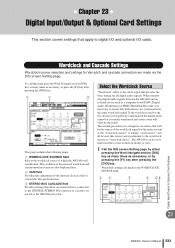
... AW2400 and an external device such as a computer-based DAW (Digital Audio Workstation) or HDR (Hard-Disk Recorder) it is to designate one device that will be the source of the wordclock signal for the entire system as the "wordclock master," or simply "clock master", and all digital audio...as necessary, or by pressing the [F1] key after pressing the [DIO] key. BA C D EF Digital Input/Output & Optional Card Settings 23 AW2400 Owner's Manual 223 Chapter 23 Digital Input/Output & Optional Card Settings This section covers settings that both devices are synchronized to the same wordclock ...
... AW2400 and an external device such as a computer-based DAW (Digital Audio Workstation) or HDR (Hard-Disk Recorder) it is to designate one device that will be the source of the wordclock signal for the entire system as the "wordclock master," or simply "clock master", and all digital audio...as necessary, or by pressing the [F1] key after pressing the [DIO] key. BA C D EF Digital Input/Output & Optional Card Settings 23 AW2400 Owner's Manual 223 Chapter 23 Digital Input/Output & Optional Card Settings This section covers settings that both devices are synchronized to the same wordclock ...
Owner's Manual
Page 224
...connecting the digital audio from a DAT recorder or similar digital audio source. the clock signal included in the rear-panel slot. The CLOCK and SYNC rows show the condition of the wordclock signal currently selected as the wordclock source. A "●" symbol will appear when the AW2400 is ... in the Fs field indicates that an appropriate wordclock signal has been selected as the wordclock source (i.e. Digital Input/Output & Optional Card Settings 23 224 AW2400 Owner's Manual In such cases check that proper synchronization with the wrong pitch and tempo if slaved to a...
...connecting the digital audio from a DAT recorder or similar digital audio source. the clock signal included in the rear-panel slot. The CLOCK and SYNC rows show the condition of the wordclock signal currently selected as the wordclock source. A "●" symbol will appear when the AW2400 is ... in the Fs field indicates that an appropriate wordclock signal has been selected as the wordclock source (i.e. Digital Input/Output & Optional Card Settings 23 224 AW2400 Owner's Manual In such cases check that proper synchronization with the wrong pitch and tempo if slaved to a...
Owner's Manual
Page 225
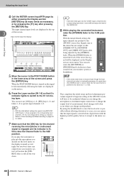
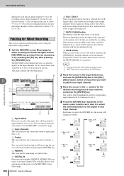
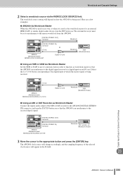
Select the 1/2-15/16 button corresponding to the digital input at a digital input on so that the AW2400 can synchronize to the received digital signal. [DIGITAL STEREO OUT] connector [DIGITAL STEREO IN] connector AW2400 (Wordclock slave) WORDCLOCK SOURCE=D.ST IN Wordclock DAT recorder, etc. (Wordclock master) 3 Move the cursor to the appropriate button and press the [ENTER] key. The...
Select the 1/2-15/16 button corresponding to the digital input at a digital input on so that the AW2400 can synchronize to the received digital signal. [DIGITAL STEREO OUT] connector [DIGITAL STEREO IN] connector AW2400 (Wordclock slave) WORDCLOCK SOURCE=D.ST IN Wordclock DAT recorder, etc. (Wordclock master) 3 Move the cursor to the appropriate button and press the [ENTER] key. The...


