
Service Guide
Page 7
... jams 42 Jams in the duplex unit 43 No imaging drum installed 43 Imaging drum up/down error 43 Fan error 44 Fuser unit error 44 Other problems 45 The printer continuously displays "Booting" or "Initializing." 45 False "No... offsetting 52 Repeating defect or voids on print 53 Missing characters or voids in print 54 Color misalignments 55 Unexpected colors 56 Image is skewed on the paper 57 Image is not centered on the print 57 ...rotated 90 degrees 58 Image prints in black-and-white 58 Printer isn't in the Chooser 59 Windows printing problems 59 Image never prints 59 vi Phaser 2135 Color Printer
... jams 42 Jams in the duplex unit 43 No imaging drum installed 43 Imaging drum up/down error 43 Fan error 44 Fuser unit error 44 Other problems 45 The printer continuously displays "Booting" or "Initializing." 45 False "No... offsetting 52 Repeating defect or voids on print 53 Missing characters or voids in print 54 Color misalignments 55 Unexpected colors 56 Image is skewed on the paper 57 Image is not centered on the print 57 ...rotated 90 degrees 58 Image prints in black-and-white 58 Printer isn't in the Chooser 59 Windows printing problems 59 Image never prints 59 vi Phaser 2135 Color Printer

Service Guide
Page 10
Drive assembly components 141 Main motor assembly 141 Imaging drum motor 142 Fuser motor and transfer belt drive motor assembly 143 Xerographic components 144 Shutter plate 144 Color registration sensor assembly 145 Color registration solenoid 146 LED assembly 147 Drum contact assembly 148 Toner sensor actuators 149 Duplex unit 151 FRU List 153 Using the parts list 153 Test Prints 173 Wiring Diagram 177 Service Guide ix
Drive assembly components 141 Main motor assembly 141 Imaging drum motor 142 Fuser motor and transfer belt drive motor assembly 143 Xerographic components 144 Shutter plate 144 Color registration sensor assembly 145 Color registration solenoid 146 LED assembly 147 Drum contact assembly 148 Toner sensor actuators 149 Duplex unit 151 FRU List 153 Using the parts list 153 Test Prints 173 Wiring Diagram 177 Service Guide ix

Service Guide
Page 12
... transfer belt drive motor assembly 143 Removing the shutter plate 144 Removing the color registration sensor assembly 145 Removing the color registration solenoid 146 Removing an LED assembly 147 Removing the drum contact assembly 148 Removing the toner sensor actuators 150 Removing the duplex unit ...151 Cabinet and top cover FRUs 155 Top cover FRUs 157 Printer chassis FRUs (1 of 2) 159 Printer chassis FRUs (2 ...
... transfer belt drive motor assembly 143 Removing the shutter plate 144 Removing the color registration sensor assembly 145 Removing the color registration solenoid 146 Removing an LED assembly 147 Removing the drum contact assembly 148 Removing the toner sensor actuators 150 Removing the duplex unit ...151 Cabinet and top cover FRUs 155 Top cover FRUs 157 Printer chassis FRUs (1 of 2) 159 Printer chassis FRUs (2 ...

Service Guide
Page 20
Duplex Solenoid Transfer Belt Drive Motor Fuser Motor Exit Solenoid Registration Motor Registration Clutch Color Registration Shutter Solenoid Tray Lift Motor Cyan Imaging Drum Motor Magenta Imaging Drum Motor Yellow Imaging Drum Motor Black Imaging Drum Motor Print engine motors, clutches and solenoids Paper Feed Motor 0725-62 Service Guide 7
Duplex Solenoid Transfer Belt Drive Motor Fuser Motor Exit Solenoid Registration Motor Registration Clutch Color Registration Shutter Solenoid Tray Lift Motor Cyan Imaging Drum Motor Magenta Imaging Drum Motor Yellow Imaging Drum Motor Black Imaging Drum Motor Print engine motors, clutches and solenoids Paper Feed Motor 0725-62 Service Guide 7

Service Guide
Page 33
...unit. 3. Black Imaging Drum Missing, Reseat Drum EA-Black Imaging Drum Missing Cyan Imaging Drum Missing, Reseat Drum EA-Cyan Imaging Drum Missing Magenta Imaging Drum Missing, Reseat Drum EA-Magenta Imaging Drum Missing Yellow Imaging Drum Missing, Reseat Drum EA-Yellow Imaging Drum Missing 1. Printer fault messages Code E14... in "Switch scan test" on page 63. 3. Inspect the sensor and its wiring harness. 4. Replace the printer unit chassis 20 Phaser 2135 Color Printer Replace the duplexer unit. 5. Ensure they are clean and move up and down freely. Remove the assembly and ...
...unit. 3. Black Imaging Drum Missing, Reseat Drum EA-Black Imaging Drum Missing Cyan Imaging Drum Missing, Reseat Drum EA-Cyan Imaging Drum Missing Magenta Imaging Drum Missing, Reseat Drum EA-Magenta Imaging Drum Missing Yellow Imaging Drum Missing, Reseat Drum EA-Yellow Imaging Drum Missing 1. Printer fault messages Code E14... in "Switch scan test" on page 63. 3. Inspect the sensor and its wiring harness. 4. Replace the printer unit chassis 20 Phaser 2135 Color Printer Replace the duplexer unit. 5. Ensure they are clean and move up and down freely. Remove the assembly and ...
Service Guide
Page 35
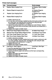
.... 4. Inspect and test the paper size sensors and the tray's corresponding sensor flags. 4. Install a new drum unit. 2. Replace the paper tray sensor board. 5. Replace the engine controller board. 22 Phaser 2135 Color Printer Inspect the spring-loaded drum unit contacts (in the tray. 2. Yellow Toner Empty Replace Yellow Toner J9-Yellow Toner Empty Magenta...
.... 4. Inspect and test the paper size sensors and the tray's corresponding sensor flags. 4. Install a new drum unit. 2. Replace the paper tray sensor board. 5. Replace the engine controller board. 22 Phaser 2135 Color Printer Inspect the spring-loaded drum unit contacts (in the tray. 2. Yellow Toner Empty Replace Yellow Toner J9-Yellow Toner Empty Magenta...

Service Guide
Page 38
...U23 U24 U25 U26 Front panel message Service message Duplex I/F Error U12, Power Off/On U12-Duplex I /F Error 1. Turn the printer off and then on. 2. Inspect the printer's corresponding connector on page 85. 3. Tray 3 I/F Error U13, Power Off/On U13-Tray 3 I/F Error Tray 2 I/F Error...procedure "Resetting NVRAM" on the printer chassis (covered by a flexible metal plate). 3. Turn the printer off and then on . 2. Replace the engine controller board. Ensure to the LED assembly. 3. Yellow Drum Error U26, Power Off/On U26-Yellow Drum Error Service Guide 25 Inspect the...
...U23 U24 U25 U26 Front panel message Service message Duplex I/F Error U12, Power Off/On U12-Duplex I /F Error 1. Turn the printer off and then on. 2. Inspect the printer's corresponding connector on page 85. 3. Tray 3 I/F Error U13, Power Off/On U13-Tray 3 I/F Error Tray 2 I/F Error...procedure "Resetting NVRAM" on the printer chassis (covered by a flexible metal plate). 3. Turn the printer off and then on . 2. Replace the engine controller board. Ensure to the LED assembly. 3. Yellow Drum Error U26, Power Off/On U26-Yellow Drum Error Service Guide 25 Inspect the...

Service Guide
Page 39
... print unit chassis. Fuse Cut Error For the new Customer Replaceable Consumable (imaging drums, transfer belt or fuser) just installed, the printer did not detect the CRC's "new/used" fuse blow. Replace the print unit chassis. 26 Phaser 2135 Color Printer Ensure they are clean and move up and down freely. Remove the assembly and...
... print unit chassis. Fuse Cut Error For the new Customer Replaceable Consumable (imaging drums, transfer belt or fuser) just installed, the printer did not detect the CRC's "new/used" fuse blow. Replace the print unit chassis. 26 Phaser 2135 Color Printer Ensure they are clean and move up and down freely. Remove the assembly and...

Service Guide
Page 43
...area by control firmware and the engine area by the data written in its idle temperature the printer is made to see that their rotation sensors are installed. Checks whether the optional units (such as... the number of bits in the fixed addresses of each other with the printer, the printer prints a startup page. 30 Phaser 2135 Color Printer EEPROM check. s The print engine checks to determine if any paper is jammed ... their relative positions to ensure that the imaging drums are detected. Flash ROM check. s After the fuser reaches its READY state.
...area by control firmware and the engine area by the data written in its idle temperature the printer is made to see that their rotation sensors are installed. Checks whether the optional units (such as... the number of bits in the fixed addresses of each other with the printer, the printer prints a startup page. 30 Phaser 2135 Color Printer EEPROM check. s The print engine checks to determine if any paper is jammed ... their relative positions to ensure that the imaging drums are detected. Flash ROM check. s After the fuser reaches its READY state.

Service Guide
Page 50
... seconds of fuser 0728-02 Service Guide 37 With a DMM set for measuring resistance, test each motor's windings for correct resistance (disconnected from the printer). Upper Roller Between Pins A and B Between Pins C and D Between Pins E and F Lower Roller Between Pins A and B Between Pins ...Ω All the drum motors connect to connector ID at 25oC C D E F C D E F Underside of being installed to connector HOPFF pins 5 thru 8 Tray lift motor Between motor Pins 1 and 2 ~100 Ω Fuser unit New fuser: The resistance between ... Turn off the printer and disconnect the power...
... seconds of fuser 0728-02 Service Guide 37 With a DMM set for measuring resistance, test each motor's windings for correct resistance (disconnected from the printer). Upper Roller Between Pins A and B Between Pins C and D Between Pins E and F Lower Roller Between Pins A and B Between Pins ...Ω All the drum motors connect to connector ID at 25oC C D E F C D E F Underside of being installed to connector HOPFF pins 5 thru 8 Tray lift motor Between motor Pins 1 and 2 ~100 Ω Fuser unit New fuser: The resistance between ... Turn off the printer and disconnect the power...

Service Guide
Page 56
... the top cover open switch, and observe if the color imaging drum unit are properly installed. 2. Test them using the service test "Switch scan test" on page 69. If a drum contact assembly is visible. 3. No imaging drum installed 1. Service Guide 43 Test the duplex motor using... Replace the engine controller board. Inspect the duplex unit for each imaging drum motor rotate. Imaging drum up and down error 1. Remove an assembly from the printer to see if the problem clears. 2. Test the drum contact assemblies using the service test "Motor and clutch tests" on page...
... the top cover open switch, and observe if the color imaging drum unit are properly installed. 2. Test them using the service test "Switch scan test" on page 69. If a drum contact assembly is visible. 3. No imaging drum installed 1. Service Guide 43 Test the duplex motor using... Replace the engine controller board. Inspect the duplex unit for each imaging drum motor rotate. Imaging drum up and down error 1. Remove an assembly from the printer to see if the problem clears. 2. Test the drum contact assemblies using the service test "Motor and clutch tests" on page...

Service Guide
Page 60
Are any of the imaging drum reaching their power terminals? 5. Replace them if they are. 4. Is the correct paper being used in the printer? 2. Are the LED heads wiring harnesses undamaged and properly seated? 7. Inspect the wiring harnesses or replace the low-voltage power supply. 10. Printing and print ... 7, 8, 9 and 10 on the junction board or at the 16-pin interconnect near the top cover hinge (under the top shield plate). Do the imaging drum units make good connection to Pin 3 of -life?
Are any of the imaging drum reaching their power terminals? 5. Replace them if they are. 4. Is the correct paper being used in the printer? 2. Are the LED heads wiring harnesses undamaged and properly seated? 7. Inspect the wiring harnesses or replace the low-voltage power supply. 10. Printing and print ... 7, 8, 9 and 10 on the junction board or at the 16-pin interconnect near the top cover hinge (under the top shield plate). Do the imaging drum units make good connection to Pin 3 of -life?
Service Guide
Page 61
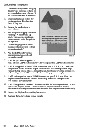
... board. (Transfer the old engine controller board's EEPROM (lower-right corner of board) to the HVOLT connector Pin 5 of the imaging drums were exposed to light for contamination. Is +3.8V (red wire) supplied to their power terminals? 6. Inspect the high-voltage wiring harnesses.... is correctly set. 4. Dark, stained background 1. A heat build-up under the top shield plate). Replace the high voltage power supply. 48 Phaser 2135 Color Printer Replace the fuser if they are. 3. Inspect the junction board's wiring connectors. If +32 volts supplied to the POWER connector pins 7, 8, ...
... board. (Transfer the old engine controller board's EEPROM (lower-right corner of board) to the HVOLT connector Pin 5 of the imaging drums were exposed to light for contamination. Is +3.8V (red wire) supplied to their power terminals? 6. Inspect the high-voltage wiring harnesses.... is correctly set. 4. Dark, stained background 1. A heat build-up under the top shield plate). Replace the high voltage power supply. 48 Phaser 2135 Color Printer Replace the fuser if they are. 3. Inspect the junction board's wiring connectors. If +32 volts supplied to the POWER connector pins 7, 8, ...

Service Guide
Page 62
Inspect the junction board's wiring connectors. Do the imaging drum units make good connection to the new engine controller board.) 7. If the voltage is not OK, replace the low-voltage power supply. 5. If not, replace ...
Inspect the junction board's wiring connectors. Do the imaging drum units make good connection to the new engine controller board.) 7. If the voltage is not OK, replace the low-voltage power supply. 5. If not, replace ...

Service Guide
Page 63
...harnesses or replace the low-voltage power supply. 6. Inspect the high-voltage wiring harnesses. 8. Replace the high voltage power supply. 50 Phaser 2135 Color Printer Do the imaging drum units make good connection to the new engine controller board.) 7. If the voltage is not OK, replace the low-voltage power supply.... top cover hinge (under the top shield plate). Black stripe in direction of paper travel Note A-size prints are processed through the printer with the long edge of the print parallel to the paper path making print artifacts parallel to the short edge of the print. ...
...harnesses or replace the low-voltage power supply. 6. Inspect the high-voltage wiring harnesses. 8. Replace the high voltage power supply. 50 Phaser 2135 Color Printer Do the imaging drum units make good connection to the new engine controller board.) 7. If the voltage is not OK, replace the low-voltage power supply.... top cover hinge (under the top shield plate). Black stripe in direction of paper travel Note A-size prints are processed through the printer with the long edge of the print parallel to the paper path making print artifacts parallel to the short edge of the print. ...

Service Guide
Page 64
...? Is +3.8V (red wire) supplied to the new engine controller board. 8. Inspect the wiring harnesses or replace the low-voltage power supply. 7. Do the imaging drum units make good connection to the POWER connector pins 1, 2, 3, 4, 5, 6, 7 and 8 on the junction board or at the 16-pin interconnect near the ... print. Is +32V supplied to the HVOLT connector Pin 5 of board) to Pin 3 of the print. B-size prints are normally processed through the printer with the long edge of the print parallel to the paper path making print artifacts parallel to the short edge of each LED head assembly...
...? Is +3.8V (red wire) supplied to the new engine controller board. 8. Inspect the wiring harnesses or replace the low-voltage power supply. 7. Do the imaging drum units make good connection to the POWER connector pins 1, 2, 3, 4, 5, 6, 7 and 8 on the junction board or at the 16-pin interconnect near the ... print. Is +32V supplied to the HVOLT connector Pin 5 of board) to Pin 3 of the print. B-size prints are normally processed through the printer with the long edge of the print parallel to the paper path making print artifacts parallel to the short edge of each LED head assembly...

Service Guide
Page 66
... the fuser. In some instances, the spots may also be shaped something other than round. Replace the fuser. Replace the imaging drum unit of the affected color. Repeating defect or voids on print This can usually be traced to a dent-like defect in the developer roller of the imaging... drum unit in .): Charging roller. Service Guide 53 Measure the spacing between the repeating spots indicates the source of the affected color. Replace the transfer belt unit. Replace the imaging drum unit of the affected...
... the fuser. In some instances, the spots may also be shaped something other than round. Replace the fuser. Replace the imaging drum unit of the affected color. Repeating defect or voids on print This can usually be traced to a dent-like defect in the developer roller of the imaging... drum unit in .): Charging roller. Service Guide 53 Measure the spacing between the repeating spots indicates the source of the affected color. Replace the transfer belt unit. Replace the imaging drum unit of the affected...

Service Guide
Page 67
... the low-voltage power supply. 8. If not replace the engine controller board. Inspect and clean the imaging drum unit's power terminals Ensure the spring-loaded pins travel smoothly up and down. 3. Inspect the wiring harnesses...the LED heads. Is +32V supplied to the POWER connector pins 7, 8, 9 and 10 on the engine controller board? Replace any imaging drum units you suspect are defective. 5. Clean them with a clean, alcohol-soaked, lint-free wipe. 2. If +32 volts supplied to the...LED head assembly. 7. Replace the high voltage power supply. 54 Phaser 2135 Color Printer
... the low-voltage power supply. 8. If not replace the engine controller board. Inspect and clean the imaging drum unit's power terminals Ensure the spring-loaded pins travel smoothly up and down. 3. Inspect the wiring harnesses...the LED heads. Is +32V supplied to the POWER connector pins 7, 8, 9 and 10 on the engine controller board? Replace any imaging drum units you suspect are defective. 5. Clean them with a clean, alcohol-soaked, lint-free wipe. 2. If +32 volts supplied to the...LED head assembly. 7. Replace the high voltage power supply. 54 Phaser 2135 Color Printer

Service Guide
Page 68
... and clutch tests" on page 63. Also test the registration solenoid, as described in the printer. Replace any imaging drum units you suspect are clean without toner dust on the senors. 2. Color misalignments 1. Inspect and clean the imaging drum unit's power terminals Ensure the spring-loaded pins travel smoothly up and down. 4. Inspect the...
... and clutch tests" on page 63. Also test the registration solenoid, as described in the printer. Replace any imaging drum units you suspect are clean without toner dust on the senors. 2. Color misalignments 1. Inspect and clean the imaging drum unit's power terminals Ensure the spring-loaded pins travel smoothly up and down. 4. Inspect the...
Service Guide
Page 69
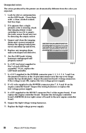
...and down. 4. If +32 volts supplied to the HVOLT connector Pin 5 of each LED head assembly? If it appears that a single primary color is missing, check that imaging drum's toner cartridge to the POWER connector pins 1, 2, 3, 4, 5, 6, 7 and 8 on the junction board or at the 16-pin ...detecting the empty sensor. 3. Is +3.8V (red wire) supplied to the new engine controller board. 10. Replace the high voltage power supply. 56 Phaser 2135 Color Printer Clean them with a clean, alcohol-soaked, lint-free wipe. 2. If yes, replace the LED head assembly. 7. Transfer the old engine controller ...
...and down. 4. If +32 volts supplied to the HVOLT connector Pin 5 of each LED head assembly? If it appears that a single primary color is missing, check that imaging drum's toner cartridge to the POWER connector pins 1, 2, 3, 4, 5, 6, 7 and 8 on the junction board or at the 16-pin ...detecting the empty sensor. 3. Is +3.8V (red wire) supplied to the new engine controller board. 10. Replace the high voltage power supply. 56 Phaser 2135 Color Printer Clean them with a clean, alcohol-soaked, lint-free wipe. 2. If yes, replace the LED head assembly. 7. Transfer the old engine controller ...


