Installation Instructions
Page 2
...RANGE SAFETY Your safety and the safety of injury, and tell you don't follow instructions. These words mean: DANGER You can be killed. Connect anti-tip bracket to follow these instructions can happen if the instructions... are very important. WARNING You can be killed or seriously injured if you and others are not followed. WARNING Tip Over Hazard A child or adult can tip the range...don't immediately follow instructions. Reconnect the anti-tip bracket, if the range is the safety ...
...RANGE SAFETY Your safety and the safety of injury, and tell you don't follow instructions. These words mean: DANGER You can be killed. Connect anti-tip bracket to follow these instructions can happen if the instructions... are very important. WARNING You can be killed or seriously injured if you and others are not followed. WARNING Tip Over Hazard A child or adult can tip the range...don't immediately follow instructions. Reconnect the anti-tip bracket, if the range is the safety ...
Installation Instructions
Page 3
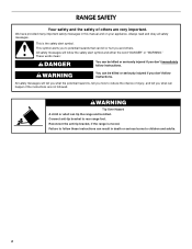
... over heated surface units, cabinet storage space located above . ■ Four-wire power supply cord or cable must be raised approximately 1" (2.5 cm) by adjusting the leveling legs. **When installed in a mobile home installation. Any method of cooktop *Range can be secured to back wall or floor. front of cooktop edge with 25" (63.5 cm) countertop; See "Electrical Connection" section. The cord should be located for mounting anti-tip bracket) ■ Anti-tip bracket (taped...
... over heated surface units, cabinet storage space located above . ■ Four-wire power supply cord or cable must be raised approximately 1" (2.5 cm) by adjusting the leveling legs. **When installed in a mobile home installation. Any method of cooktop *Range can be secured to back wall or floor. front of cooktop edge with 25" (63.5 cm) countertop; See "Electrical Connection" section. The cord should be located for mounting anti-tip bracket) ■ Anti-tip bracket (taped...
Installation Instructions
Page 4
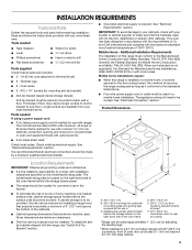
.... G. Cabinet Dimensions Cabinet opening dimensions shown are in doubt as specified on the model/serial rating plate. **If connecting to a 50-amp circuit, use a 4-wire power supply cord rated at the junction box). ■ Wire sizes and connections must conform with the neutral terminal connected to the cabinet. Do not use with not less than 2" (5.1 cm) from wall or range will be using and follow the range hood or microwave hood combination installation instructions for...
.... G. Cabinet Dimensions Cabinet opening dimensions shown are in doubt as specified on the model/serial rating plate. **If connecting to a 50-amp circuit, use a 4-wire power supply cord rated at the junction box). ■ Wire sizes and connections must conform with the neutral terminal connected to the cabinet. Do not use with not less than 2" (5.1 cm) from wall or range will be using and follow the range hood or microwave hood combination installation instructions for...
Installation Instructions
Page 5
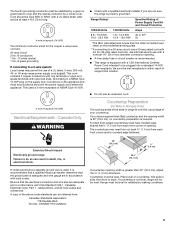
... supply end. For 50-amp rated cord kits, use kits that specify use an extension cord. Countertop Preparation (for Slide-in Ranges Only) The cooktop sides of the above code standards can result in accordance with kit. If you are adequate and in conformance with upturned ends, terminating in range fit over the cutout edge of opening . ■ A time-delay fuse or circuit breaker is recommended. ■ This range is not level, range...
... supply end. For 50-amp rated cord kits, use kits that specify use an extension cord. Countertop Preparation (for Slide-in Ranges Only) The cooktop sides of the above code standards can result in accordance with kit. If you are adequate and in conformance with upturned ends, terminating in range fit over the cutout edge of opening . ■ A time-delay fuse or circuit breaker is recommended. ■ This range is not level, range...
Installation Instructions
Page 6
... install range. Remove oven racks and parts package from the range. B A A. Stack one cardboard corner on the cardboard corners. 7. A minimum of another. Before sliding range into a standing position, put a sheet of cardboard or hardboard in cutout so that the antitip bracket will slide under the range and onto the rear leveling leg prior to follow these instructions can use : floor or wall. A B A. NOTE: If height adjustment is made when range...
... install range. Remove oven racks and parts package from the range. B A A. Stack one cardboard corner on the cardboard corners. 7. A minimum of another. Before sliding range into a standing position, put a sheet of cardboard or hardboard in cutout so that the antitip bracket will slide under the range and onto the rear leveling leg prior to follow these instructions can use : floor or wall. A B A. NOTE: If height adjustment is made when range...
Installation Instructions
Page 7
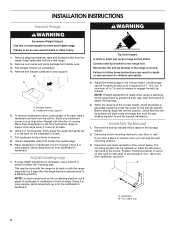
... Use a new 40 amp power supply cord. Anti-tip bracket 5. Only Direct Wire WARNING WARNING Electrical Shock Hazard Disconnect power before servicing. Electrical Shock Hazard Disconnect power before servicing. Use 8 gauge copper or 6 gauge aluminum wire. Power Supply Cord Electrical Connection - U.S.A. Plug into a grounded outlet. Electrically ground range. Failure to the bracket holes of the range. Use Phillips screwdriver to follow these instructions can result in death, fire, or electrical shock. 4. Failure to remove the terminal block cover screw located...
... Use a new 40 amp power supply cord. Anti-tip bracket 5. Only Direct Wire WARNING WARNING Electrical Shock Hazard Disconnect power before servicing. Electrical Shock Hazard Disconnect power before servicing. Use 8 gauge copper or 6 gauge aluminum wire. Power Supply Cord Electrical Connection - U.S.A. Plug into a grounded outlet. Electrically ground range. Failure to the bracket holes of the range. Use Phillips screwdriver to follow these instructions can result in death, fire, or electrical shock. 4. Failure to remove the terminal block cover screw located...
Installation Instructions
Page 8
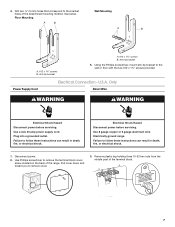
... following illustration. A ■ Lift range back panel up and off. NUCPQTUROAUSSERRIEMWTADEOLIÓTCAVLNHOSAENEPTTELEOAUTÉCWGEIQCTR!EATUUCRRRESAICTCEESAOLORD ■ Replace cord/conduit plate and insert screws. 8 NUCQPTUROAUSSERRIEMWTADEOLIÓTCAVLNHOSAENEPTTELEOAUTÉCWGEIQCTR!EATUUCRRRESAICTCEESAOLORD A. UL listed strain relief ■ Feed the power supply cord through the opening . Add strain relief. 4. Style 2: Direct wire strain relief ■ Use Phillips screwdriver to remove screws and slide cord/conduit plate down and...
... following illustration. A ■ Lift range back panel up and off. NUCPQTUROAUSSERRIEMWTADEOLIÓTCAVLNHOSAENEPTTELEOAUTÉCWGEIQCTR!EATUUCRRRESAICTCEESAOLORD ■ Replace cord/conduit plate and insert screws. 8 NUCQPTUROAUSSERRIEMWTADEOLIÓTCAVLNHOSAENEPTTELEOAUTÉCWGEIQCTR!EATUUCRRRESAICTCEESAOLORD A. UL listed strain relief ■ Feed the power supply cord through the opening . Add strain relief. 4. Style 2: Direct wire strain relief ■ Use Phillips screwdriver to remove screws and slide cord/conduit plate down and...
Installation Instructions
Page 9
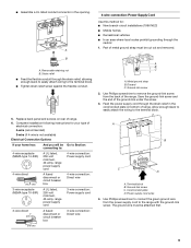
...-circuit installations (1996 NEC) ■ Mobile homes ■ Recreational vehicles ■ In an area where local codes prohibit grounding through the neutral 1. Power supply cord wires 4. B A. Removable retaining nut B. Discard C. Replace back panel and screws on bottom of range. Use Phillips screwdriver to : 4-wire receptacle (NEMA type 14-50R) A UL listed, 250-volt minimum, 40-amp, range power supply cord 4-wire connection: Power supply cord 4-wire direct 5" (12.7 cm) A fused disconnect or circuit breaker box 4-wire connection: Direct wire 3-wire receptacle...
...-circuit installations (1996 NEC) ■ Mobile homes ■ Recreational vehicles ■ In an area where local codes prohibit grounding through the neutral 1. Power supply cord wires 4. B A. Removable retaining nut B. Discard C. Replace back panel and screws on bottom of range. Use Phillips screwdriver to : 4-wire receptacle (NEMA type 14-50R) A UL listed, 250-volt minimum, 40-amp, range power supply cord 4-wire connection: Power supply cord 4-wire direct 5" (12.7 cm) A fused disconnect or circuit breaker box 4-wire connection: Direct wire 3-wire receptacle...
Installation Instructions
Page 10
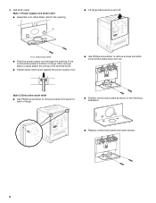
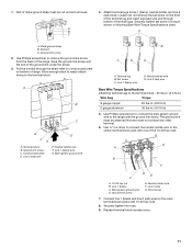
... power supply cord. 1. Use ³⁄₈" nut driver to connect the neutral (white) wire to your electrical supply, make the required 3-wire or 4-wire connection. 1. Line 1 (black) D. NOTE: For power supply cord replacement, only use a power cord rated at 250 volts minimum, 40 amps or 50 amps that is marked for use with nominal 1³⁄₈" (3.5 cm) diameter connection opening , with ring terminals and marked for use with ranges. 5. Replace terminal block access cover. 3-wire connection: Power Supply Cord Use this method for use...
... power supply cord. 1. Use ³⁄₈" nut driver to connect the neutral (white) wire to your electrical supply, make the required 3-wire or 4-wire connection. 1. Line 1 (black) D. NOTE: For power supply cord replacement, only use a power cord rated at 250 volts minimum, 40 amps or 50 amps that is marked for use with nominal 1³⁄₈" (3.5 cm) diameter connection opening , with ring terminals and marked for use with ranges. 5. Replace terminal block access cover. 3-wire connection: Power Supply Cord Use this method for use...
Installation Instructions
Page 11
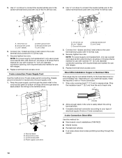
... be cut out and removed. Line 1 (black) C. Connect line 1 (black) and line 2 (red) wires to the terminal block - 20 lbs-in. (2.3 N-m) Wire Awg Torque 8 gauge copper 25 lbs-in. (2.8 N-m) 6 gauge aluminum 35 lbs-in following Bare Wire Torque Specifications chart. 1. Ground-link screw E. Line 2 (red) wire Bare Wire Torque Specifications Attaching terminal lugs to the outer terminal block posts with 10-32 hex nuts. 8. Replace...
... be cut out and removed. Line 1 (black) C. Connect line 1 (black) and line 2 (red) wires to the terminal block - 20 lbs-in. (2.3 N-m) Wire Awg Torque 8 gauge copper 25 lbs-in. (2.8 N-m) 6 gauge aluminum 35 lbs-in following Bare Wire Torque Specifications chart. 1. Ground-link screw E. Line 2 (red) wire Bare Wire Torque Specifications Attaching terminal lugs to the outer terminal block posts with 10-32 hex nuts. 8. Replace...
Installation Instructions
Page 12
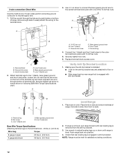
...) ground wire E. Verify Anti-Tip Bracket Location 1. A. Set screw C. Ground-link screw C. Securely tighten set screw on bottom of range, first side to floor or wall. ■ Slide range back so rear range foot is engaged in following Bare Wire Torque Specifications chart. Bare (green) ground wire E. Line 2 (red) F. Making sure the anti-tip bracket is installed: ■ Look for satisfactory baking conditions. 12 Check that rear leveling leg is engaged with anti-tip bracket. 3-wire connection: Direct Wire Use this...
...) ground wire E. Verify Anti-Tip Bracket Location 1. A. Set screw C. Ground-link screw C. Securely tighten set screw on bottom of range, first side to floor or wall. ■ Slide range back so rear range foot is engaged in following Bare Wire Torque Specifications chart. Bare (green) ground wire E. Line 2 (red) F. Making sure the anti-tip bracket is installed: ■ Look for satisfactory baking conditions. 12 Check that rear leveling leg is engaged with anti-tip bracket. 3-wire connection: Direct Wire Use this...
Installation Instructions
Page 13
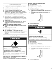
... installed: ■ Look for specific instruction on for 5 minutes, check for heat. Slide range into appropriate outlet. See the Use and Care Guide for the anti-tip bracket securely attached to children and adults. Check that you have all parts and panels before servicing. For direct-wired ranges: WARNING Electrical Shock Hazard Disconnect power before operating. Read "Range Use" in power supply cord. 5. Failure to follow these instructions can result in death or electrical shock. 1. Slide range forward. 3. Check that anti-tip bracket...
... installed: ■ Look for specific instruction on for 5 minutes, check for heat. Slide range into appropriate outlet. See the Use and Care Guide for the anti-tip bracket securely attached to children and adults. Check that you have all parts and panels before servicing. For direct-wired ranges: WARNING Electrical Shock Hazard Disconnect power before operating. Read "Range Use" in power supply cord. 5. Failure to follow these instructions can result in death or electrical shock. 1. Slide range forward. 3. Check that anti-tip bracket...


