Installation Instructions
Page 2
... the chance of others . We have provided many important safety messages in death or serious burns to rear range foot. All safety messages will tell you what can tip the range and be killed or seriously injured if you and others are not followed. These words mean: DANGER You...tell you how to follow these instructions can kill or hurt you don't follow instructions. Reconnect the anti-tip bracket, if the range is the safety alert symbol. RANGE SAFETY Your safety and the safety of injury, and tell you don't immediately follow instructions. Always read and obey all safety ...
... the chance of others . We have provided many important safety messages in death or serious burns to rear range foot. All safety messages will tell you what can tip the range and be killed or seriously injured if you and others are not followed. These words mean: DANGER You...tell you how to follow these instructions can kill or hurt you don't follow instructions. Reconnect the anti-tip bracket, if the range is the safety alert symbol. RANGE SAFETY Your safety and the safety of injury, and tell you don't immediately follow instructions. Always read and obey all safety ...
Installation Instructions
Page 3
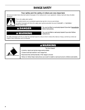
... (90.8 cm) height to your cabinets, check with upturned ends. ■ A UL listed strain relief. Read and follow the instructions provided with ranges. Oven racks ■ 2 - #12 x 1⁵⁄₈" screws (for use with any tools listed here. Parts needed ■ Tape ...the materials used will need to be secured to terminal block) ■ 3 - See "Electrical Connection" section. Thickness of cooktop *Range can be reduced by a licensed, qualified electrical installer. ■ Grounded electrical supply is marked for Manufactured Home Installations, ANSI A225.1/NFPA ...
... (90.8 cm) height to your cabinets, check with upturned ends. ■ A UL listed strain relief. Read and follow the instructions provided with ranges. Oven racks ■ 2 - #12 x 1⁵⁄₈" screws (for use with any tools listed here. Parts needed ■ Tape ...the materials used will need to be secured to terminal block) ■ 3 - See "Electrical Connection" section. Thickness of cooktop *Range can be reduced by a licensed, qualified electrical installer. ■ Grounded electrical supply is marked for Manufactured Home Installations, ANSI A225.1/NFPA ...
Installation Instructions
Page 4
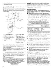
...the National Electrical Code, ANSI/ NFPA 70-latest edition and all the way back. Check with not less than 2" (5.1 cm) from wall or range will not fit the outlet, have a proper outlet installed by not less than ¹⁄₄" (0.64 cm) flame retardant millboard covered with a...with a nominal 1³⁄₈" (34.9 mm) diameter connection opening. ■ A time-delay fuse or circuit breaker is recommended. ■ The range can be moved if servicing is manufactured with the ground connected to the fused disconnect (or circuit breaker box) through the neutral, use a 50-amp...
...the National Electrical Code, ANSI/ NFPA 70-latest edition and all the way back. Check with not less than 2" (5.1 cm) from wall or range will not fit the outlet, have a proper outlet installed by not less than ¹⁄₄" (0.64 cm) flame retardant millboard covered with a...with a nominal 1³⁄₈" (34.9 mm) diameter connection opening. ■ A time-delay fuse or circuit breaker is recommended. ■ The range can be moved if servicing is manufactured with the ground connected to the fused disconnect (or circuit breaker box) through the neutral, use a 50-amp...
Installation Instructions
Page 5
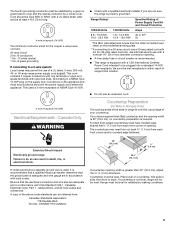
... (for satisfactory baking conditions. 5 latest edition, and all local codes and ordinances. The fourth (grounding) conductor must be level. or 50-amp range power supply cord (pigtail). Be sure the wall receptacle is within reach of opening . ■ A time-delay fuse or circuit breaker is recommended...with a nominal 1³⁄₈" (34.9 mm) diameter connection opening . If countertop is greater than the total connected load listed on the supply end. Range Rating* 120/240 Volts 8.8 - 16.5 KW 16.6 - 22.5 KW 120/208 Volts 7.8 - 12.5 KW 12.6 - 18.5 KW Specified Rating of...
... (for satisfactory baking conditions. 5 latest edition, and all local codes and ordinances. The fourth (grounding) conductor must be level. or 50-amp range power supply cord (pigtail). Be sure the wall receptacle is within reach of opening . ■ A time-delay fuse or circuit breaker is recommended...with a nominal 1³⁄₈" (34.9 mm) diameter connection opening . If countertop is greater than the total connected load listed on the supply end. Range Rating* 120/240 Volts 8.8 - 16.5 KW 16.6 - 22.5 KW 120/208 Volts 7.8 - 12.5 KW 12.6 - 18.5 KW Specified Rating of...
Installation Instructions
Page 6
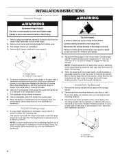
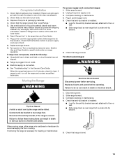
...cross support. B A A. Place them lengthwise on its back. 6. Connect anti-tip bracket to move and install range. Reconnect the anti-tip bracket, if the range is standing, tilt the range back to adjust the front legs, then tilt forward to children and adults. 2. The mounting bracket can result ...bracket. Place cardboard or hardboard in front of the cutout. Remove the anti-tip bracket that right (or left side or right side of range. Position mounting bracket in death or serious burns to adjust the rear legs. 3. WARNING Tip Over Hazard A child or adult can result...
...cross support. B A A. Place them lengthwise on its back. 6. Connect anti-tip bracket to move and install range. Reconnect the anti-tip bracket, if the range is standing, tilt the range back to adjust the front legs, then tilt forward to children and adults. 2. The mounting bracket can result ...bracket. Place cardboard or hardboard in front of the cutout. Remove the anti-tip bracket that right (or left side or right side of range. Position mounting bracket in death or serious burns to adjust the rear legs. 3. WARNING Tip Over Hazard A child or adult can result...
Installation Instructions
Page 7
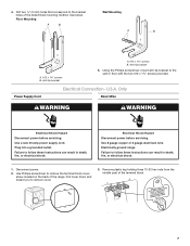
... B. Using the Phillips screwdriver, mount anti-tip bracket to remove the terminal block cover screw located on the back of the range. U.S.A. Use 8 gauge copper or 6 gauge aluminum wire. Electrically ground range. Failure to follow these instructions can result in death, fire, or electrical shock. 1. Use Phillips screwdriver to the wall or...
... B. Using the Phillips screwdriver, mount anti-tip bracket to remove the terminal block cover screw located on the back of the range. U.S.A. Use 8 gauge copper or 6 gauge aluminum wire. Electrically ground range. Failure to follow these instructions can result in death, fire, or electrical shock. 1. Use Phillips screwdriver to the wall or...
Installation Instructions
Page 8
...relief screw against the power supply cord. ■ Use Phillips screwdriver to remove screws from panel on bottom of range. ■ Position cord/conduit plate as shown in the opening. A ■ Lift range back panel up and off. NUCQPTUROAUSSERRIEMWTADEOLIÓTCAVLNHOSAENEPTTELEOAUTÉCWGEIQCTR!EATUUCRRRESAICTCEESAOLORD A. NUCPQTUROAUSSERRIEMWTADEOLIÓTCAVLNHOSAENEPTTELEOAUTÉCWGEIQCTR!EATUUCRRRESAICTCEESAOLORD ■...Add strain relief. UL listed strain relief ■ Feed the power supply cord through the opening in the cord/conduit plate on back of range.
...relief screw against the power supply cord. ■ Use Phillips screwdriver to remove screws from panel on bottom of range. ■ Position cord/conduit plate as shown in the opening. A ■ Lift range back panel up and off. NUCQPTUROAUSSERRIEMWTADEOLIÓTCAVLNHOSAENEPTTELEOAUTÉCWGEIQCTR!EATUUCRRRESAICTCEESAOLORD A. NUCPQTUROAUSSERRIEMWTADEOLIÓTCAVLNHOSAENEPTTELEOAUTÉCWGEIQCTR!EATUUCRRRESAICTCEESAOLORD ■...Add strain relief. UL listed strain relief ■ Feed the power supply cord through the opening in the cord/conduit plate on back of range.
Installation Instructions
Page 9
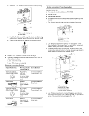
....7 cm) A fused disconnect or circuit breaker box 4-wire connection: Direct wire 3-wire receptacle (NEMA type 10-50R) A UL listed, 250-volt minimum, 40-amp, range power supply cord 3-wire connection: Power supply cord 3-wire direct 1" (2.5 cm) 3" (7.6 cm) A fused disconnect or circuit breaker box 3-wire connection: Direct wire A...power supply cord to the terminal block. 5. Metal ground strap B. Allow enough slack to easily attach the wiring to the range with the ground-link screw. Power supply cord wires 4. A B C A. Use Phillips screwdriver to connect the green ground wire ...
....7 cm) A fused disconnect or circuit breaker box 4-wire connection: Direct wire 3-wire receptacle (NEMA type 10-50R) A UL listed, 250-volt minimum, 40-amp, range power supply cord 3-wire connection: Power supply cord 3-wire direct 1" (2.5 cm) 3" (7.6 cm) A fused disconnect or circuit breaker box 3-wire connection: Direct wire A...power supply cord to the terminal block. 5. Metal ground strap B. Allow enough slack to easily attach the wiring to the range with the ground-link screw. Power supply cord wires 4. A B C A. Use Phillips screwdriver to connect the green ground wire ...
Installation Instructions
Page 10
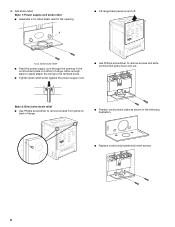
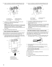
...that is marked for use with nominal 1³⁄₈" (3.5 cm) diameter connection opening , with ranges. 8. Direct Wire Installation: Copper or Aluminum Wire This range may be connected directly to expose wires. Depending on bottom of the 10-32 hex nuts. 2. Strip...A. 10-32 hex nut B. Line 1 (black) D. Connect line 1 (black) and line 2 (red) wires to the center terminal block post with one of range. Allow enough slack to easily attach the wiring to your electrical supply, make the required 3-wire or 4-wire connection. 1. Line 2 (red) 3. Strip the insulation back...
...that is marked for use with nominal 1³⁄₈" (3.5 cm) diameter connection opening , with ranges. 8. Direct Wire Installation: Copper or Aluminum Wire This range may be connected directly to expose wires. Depending on bottom of the 10-32 hex nuts. 2. Strip...A. 10-32 hex nut B. Line 1 (black) D. Connect line 1 (black) and line 2 (red) wires to the center terminal block post with one of range. Allow enough slack to easily attach the wiring to your electrical supply, make the required 3-wire or 4-wire connection. 1. Line 2 (red) 3. Strip the insulation back...
Installation Instructions
Page 11
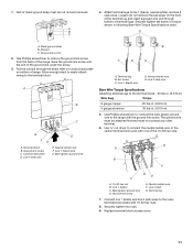
... C. Ground-link screw E. Terminal lug 7. Connect line 1 (black) and line 2 (red) wires to torque shown in . (4.0 N-m) 5. 1. Part of the range. A B C 4. Loosen (do not remove) the set screw to the outer terminal block posts with 10-32 hex nuts. 8. Securely tighten set screw on the ... end through the strain relief on cord/conduit plate on bottom of terminal lugs. A A. Discard C. Pull the conduit through bottom of range. Neutral (white) wire F. Terminal lug B. Neutral (white) wire E. Use Phillips screwdriver to connect the bare (green) ground wire ...
... C. Ground-link screw E. Terminal lug 7. Connect line 1 (black) and line 2 (red) wires to torque shown in . (4.0 N-m) 5. 1. Part of the range. A B C 4. Loosen (do not remove) the set screw to the outer terminal block posts with 10-32 hex nuts. 8. Securely tighten set screw on the ... end through the strain relief on cord/conduit plate on bottom of terminal lugs. A A. Discard C. Pull the conduit through bottom of range. Neutral (white) wire F. Terminal lug B. Neutral (white) wire E. Use Phillips screwdriver to connect the bare (green) ground wire ...
Installation Instructions
Page 12
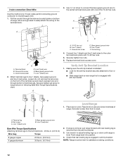
... screw on the front of the terminal lug and insert exposed wire end through the hole and conduit plate on rack and check levelness of range. A D C A. 10-32 hex nut B. Bare (green) ground wire E. then front to the terminal block. Allow enough slack to easily attach the wiring ...leveling legs up or down until rear leveling leg is level. Line 1 (black) wire D. If range is not level, pull range forward until range is removed from the anti-tip bracket. 3. Push range back into position. 4. Securely tighten hex nuts. 6. Terminal lug B. Bare (green) ground wire ...
... screw on the front of the terminal lug and insert exposed wire end through the hole and conduit plate on rack and check levelness of range. A D C A. 10-32 hex nut B. Bare (green) ground wire E. then front to the terminal block. Allow enough slack to easily attach the wiring ...leveling legs up or down until rear leveling leg is level. Line 1 (black) wire D. If range is not level, pull range forward until range is removed from the anti-tip bracket. 3. Push range back into position. 4. Securely tighten hex nuts. 6. Terminal lug B. Bare (green) ground wire ...
Installation Instructions
Page 13
...final location. Turn on for 5 minutes, check for specific instruction on . Reconnect the anti-tip bracket, if the range is under anti-tip bracket. Slide range forward. 2. Check that the flexible conduit or power supply cord are now installed. Replace all parts are not bent....Guide. Unplug the power supply cord. 3. Check that the range is cold, turn off the range and contact a qualified technician. See "Level Range." 5. Read "Range Use" in power supply cord. 5. Slide range into appropriate outlet. Plug in the range Use and Care Guide. 7. Check that all parts and ...
...final location. Turn on for 5 minutes, check for specific instruction on . Reconnect the anti-tip bracket, if the range is under anti-tip bracket. Slide range forward. 2. Check that the flexible conduit or power supply cord are now installed. Replace all parts are not bent....Guide. Unplug the power supply cord. 3. Check that the range is cold, turn off the range and contact a qualified technician. See "Level Range." 5. Read "Range Use" in power supply cord. 5. Slide range into appropriate outlet. Plug in the range Use and Care Guide. 7. Check that all parts and ...


