
Owners Manual
Page 3
...known to the State of California to potential hazards that can happen if the instructions are very important. This symbol alerts you how to cause cancer. We have provided many important safety messages in this manual and on your appliance. This is , tell you to cause birth defects ...or other reproductive harm. 3 VENT SYSTEM SAFETY Your safety and the safety of others . Always read and obey all safety messages...
...known to the State of California to potential hazards that can happen if the instructions are very important. This symbol alerts you how to cause cancer. We have provided many important safety messages in this manual and on your appliance. This is , tell you to cause birth defects ...or other reproductive harm. 3 VENT SYSTEM SAFETY Your safety and the safety of others . Always read and obey all safety messages...

Owners Manual
Page 4
IMPORTANT SAFETY INSTRUCTIONS READ AND SAVE THESE INSTRUCTIONS 4
IMPORTANT SAFETY INSTRUCTIONS READ AND SAVE THESE INSTRUCTIONS 4
Owners Manual
Page 5
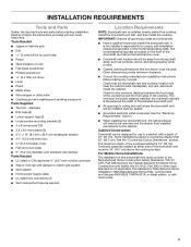
... as required Location Requirements NOTE: Downdraft vent is located on the model/serial/rating plate. stainless ■■ End caps (2) ■■ Lower support legs (2) ■■ Undercounter mounting brackets (2) ■■ 4 x 8 mm screws (16) ■■ 3.5 x 9.5 mm screws (3) ■■ 31/4" x 10" (8.3 cm x 25.4 cm) rectangular damper ■■ 43/4" (12.0 cm) motor box 6.4 mm) deep cover ■■ Flat vent cover plate ■■ 6" (15.2 cm) diameter vent transition with damper Parts Needed ■■ UL listed...
... as required Location Requirements NOTE: Downdraft vent is located on the model/serial/rating plate. stainless ■■ End caps (2) ■■ Lower support legs (2) ■■ Undercounter mounting brackets (2) ■■ 4 x 8 mm screws (16) ■■ 3.5 x 9.5 mm screws (3) ■■ 31/4" x 10" (8.3 cm x 25.4 cm) rectangular damper ■■ 43/4" (12.0 cm) motor box 6.4 mm) deep cover ■■ Flat vent cover plate ■■ 6" (15.2 cm) diameter vent transition with damper Parts Needed ■■ UL listed...

Owners Manual
Page 6
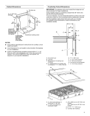
...Dimensions 13¹⁄₂" (34.3 cm) retractable vent height Top trim widths: 30" (76.2 cm) 36" (91.4 cm) 27" (68.6 cm) for 30" (76.2 cm) vent 33" (83.8 cm) for 36" (91.4 cm) vent 1¹⁄₂" (3.8 cm 0.95 cm) 13¹⁄₈" (33.4 cm) 16¹⁄₂" (42.0 cm) As-Received Blower...(76.2 cm) vent 8¹⁄₄" (21.0 cm) for 36" (91.4 cm) vent 28¹⁄₂" (72.4 cm) ³⁄₄" (1.9 cm) 10" (25.4 cm) 2¹⁄₈" (5.4 cm) Reversed Blower Front of Range Hood 10" (25.4 cm) Front of Range Hood 4³⁄₄"...
...Dimensions 13¹⁄₂" (34.3 cm) retractable vent height Top trim widths: 30" (76.2 cm) 36" (91.4 cm) 27" (68.6 cm) for 30" (76.2 cm) vent 33" (83.8 cm) for 36" (91.4 cm) vent 1¹⁄₂" (3.8 cm 0.95 cm) 13¹⁄₈" (33.4 cm) 16¹⁄₂" (42.0 cm) As-Received Blower...(76.2 cm) vent 8¹⁄₄" (21.0 cm) for 36" (91.4 cm) vent 28¹⁄₂" (72.4 cm) ³⁄₄" (1.9 cm) 10" (25.4 cm) 2¹⁄₈" (5.4 cm) Reversed Blower Front of Range Hood 10" (25.4 cm) Front of Range Hood 4³⁄₄"...
Owners Manual
Page 7
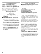
... with your specific installation. See the Installation Instructions that the cooktop and vent cutouts be drawn on the countertop before making any cutouts. D = E + 113/16" (46.2 mm) E. Downdraft vent B. D = Measurement of the cabinet. Cooktop rear overhang 7 Locate power supply junction box at lower left-hand rear corner of cooktop rear overhang (C) + 113/16" (46.2 mm) (E) B E. 113/16" (46.2 mm) F. ½" (12.7 mm) minimum G. ¼" (6.4 mm) minimum H. Some models require a countertop deeper...
... with your specific installation. See the Installation Instructions that the cooktop and vent cutouts be drawn on the countertop before making any cutouts. D = E + 113/16" (46.2 mm) E. Downdraft vent B. D = Measurement of the cabinet. Cooktop rear overhang 7 Locate power supply junction box at lower left-hand rear corner of cooktop rear overhang (C) + 113/16" (46.2 mm) (E) B E. 113/16" (46.2 mm) F. ½" (12.7 mm) minimum G. ¼" (6.4 mm) minimum H. Some models require a countertop deeper...
Owners Manual
Page 8
...-amp, fused electrical circuit is located on the model/serial/rating plate. Connect a section of Vent System" chart. Follow the electrical connector manufacturer's recommended procedure. Aluminum/copper connection must conform with local codes and industry accepted wiring practices. ■■ Wire sizes and connections must conform to the requirements of straight vent between the elbows if more than specified CFM of rigid metal vent. Venting Requirements IMPORTANT: Make sure there is proper clearance within the wall or floor before making exhaust vent cutouts...
...-amp, fused electrical circuit is located on the model/serial/rating plate. Connect a section of Vent System" chart. Follow the electrical connector manufacturer's recommended procedure. Aluminum/copper connection must conform with local codes and industry accepted wiring practices. ■■ Wire sizes and connections must conform to the requirements of straight vent between the elbows if more than specified CFM of rigid metal vent. Venting Requirements IMPORTANT: Make sure there is proper clearance within the wall or floor before making exhaust vent cutouts...

Owners Manual
Page 9
... the floor. INSTALLATION INSTRUCTIONS Venting Methods Determine which venting method is required from the blower motor box. Vent System Installed Under a Concrete Slab Using PVC Sewer Pipe Island Location Front-Mounted Blower Motor (Standard) Rear-Mounted Blower Motor Front-Mounted Blower Motor (Standard) B A D M C E F G A A L H K J I A. Down vent NOTE: For island locations, a front- Vent system can be transitioned to be mounted for your application. Built-In Cabinet Location Rear-Mounted Blower Motor B A D M C L E F G H A B A. Left vent C.
... the floor. INSTALLATION INSTRUCTIONS Venting Methods Determine which venting method is required from the blower motor box. Vent System Installed Under a Concrete Slab Using PVC Sewer Pipe Island Location Front-Mounted Blower Motor (Standard) Rear-Mounted Blower Motor Front-Mounted Blower Motor (Standard) B A D M C E F G A A L H K J I A. Down vent NOTE: For island locations, a front- Vent system can be transitioned to be mounted for your application. Built-In Cabinet Location Rear-Mounted Blower Motor B A D M C L E F G H A B A. Left vent C.

Owners Manual
Page 10
... countertop Downdraft vent 28¹⁄₂" (73 cm) "X" "Y" Cabinet floor 10 wall cap = 0.0 ft (0.0 m) 8 ft (2.4 m) straight = 8.0 ft (2.4 m) Transition = 4.5 ft (1.4 m) Length of a flat surface where you need, add the equivalent feet (meters) for each vent piece used in back or other injury. 1. Remove parts packages, downdraft vent, and blower box from distance "X" to determine dimension "Y" (X - 281/2" = Y). Subtract 281/2" (72.4 cm) from the carton. 3. Blower motor B. Failure to move and install downdraft vent...
... countertop Downdraft vent 28¹⁄₂" (73 cm) "X" "Y" Cabinet floor 10 wall cap = 0.0 ft (0.0 m) 8 ft (2.4 m) straight = 8.0 ft (2.4 m) Transition = 4.5 ft (1.4 m) Length of a flat surface where you need, add the equivalent feet (meters) for each vent piece used in back or other injury. 1. Remove parts packages, downdraft vent, and blower box from distance "X" to determine dimension "Y" (X - 281/2" = Y). Subtract 281/2" (72.4 cm) from the carton. 3. Blower motor B. Failure to move and install downdraft vent...
Owners Manual
Page 11
... slot shoulder screws. Blower Motor" section. Remove the 4 screws from motor if needed. 5. Vent cover plate F. NOTE: Disconnect the electrical wiring connection from the cover plate mounted to motor if removed. 8. NOTE: Reinstall the electrical wiring connection to the face of the vent box with 4 - 4 x 8 mm screws in a cabinet, vent system can exhaust through the bottom, left or right side to the chosen venting direction and secure to be used. 6. Reinstall the cover plate to the side of the motor box and set them aside...
... slot shoulder screws. Blower Motor" section. Remove the 4 screws from motor if needed. 5. Vent cover plate F. NOTE: Disconnect the electrical wiring connection from the cover plate mounted to motor if removed. 8. NOTE: Reinstall the electrical wiring connection to the face of the vent box with 4 - 4 x 8 mm screws in a cabinet, vent system can exhaust through the bottom, left or right side to the chosen venting direction and secure to be used. 6. Reinstall the cover plate to the side of the motor box and set them aside...

Owners Manual
Page 12
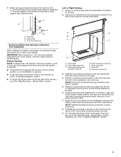
...of the ¼" (6.4 mm) deep cover. Lift the ¼" (6.4 mm) deep cover off the shoulder screws in the keyhole slots and set blower motor box aside. 3. Disconnect wire connection from the wire-mounting plate. Screws (7) B. Blower motor box 2. Remove the screws from blower motor and set the cover aside. 5. Deep cover 4. A. Rear Mounting - Blower Motor NOTE: Optional blower motor rear-mounting position (opposite side) for island cabinet location. The blower motor box assembly can be moved to the opposite side (rear) of the vent box. 1. Rear View Front View...
...of the ¼" (6.4 mm) deep cover. Lift the ¼" (6.4 mm) deep cover off the shoulder screws in the keyhole slots and set blower motor box aside. 3. Disconnect wire connection from the wire-mounting plate. Screws (7) B. Blower motor box 2. Remove the screws from blower motor and set the cover aside. 5. Deep cover 4. A. Rear Mounting - Blower Motor NOTE: Optional blower motor rear-mounting position (opposite side) for island cabinet location. The blower motor box assembly can be moved to the opposite side (rear) of the vent box. 1. Rear View Front View...

Owners Manual
Page 13
... vent box using the 6 screws previously removed. 13. Wire-mounting plate B. Install the wire mounting plate to the front of the vent box and reconnect the wire connection to the "Complete Installation" section. 12. A 9. Mount the blower motor box to the opposite side of the wire-mounting plate. Deep cover B. A 14. Hold the wire-mounting plate and push the grommet out of the vent box. 6. Remove the front cover from the ¼" (6.4 mm) deep cover. 13 Place the wire assembly through the slot in the wire-mounting plate to the wire-mounting plate...
... vent box using the 6 screws previously removed. 13. Wire-mounting plate B. Install the wire mounting plate to the front of the vent box and reconnect the wire connection to the "Complete Installation" section. 12. A 9. Mount the blower motor box to the opposite side of the wire-mounting plate. Deep cover B. A 14. Hold the wire-mounting plate and push the grommet out of the vent box. 6. Remove the front cover from the ¼" (6.4 mm) deep cover. 13 Place the wire assembly through the slot in the wire-mounting plate to the wire-mounting plate...

Owners Manual
Page 14
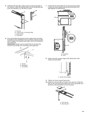
...) backdraft damper 6" (15.2 cm) Round Vent Transition with damper E F A. A. Rear of downdraft vent B. Remove the appropriate knockout from the front or rear panel and install a 1/2" (12.7 mm) UL listed or CSA approved conduit connector. 4. Complete Installation NOTE: The downdraft vent system is centered in the cutout with the rear flange over the edge of the cutout and the rear of the vent box against the edge of cutout in the blower motor box, using three 3.5 x 9.5 mm screws. Refer to the vent...
...) backdraft damper 6" (15.2 cm) Round Vent Transition with damper E F A. A. Rear of downdraft vent B. Remove the appropriate knockout from the front or rear panel and install a 1/2" (12.7 mm) UL listed or CSA approved conduit connector. 4. Complete Installation NOTE: The downdraft vent system is centered in the cutout with the rear flange over the edge of the cutout and the rear of the vent box against the edge of cutout in the blower motor box, using three 3.5 x 9.5 mm screws. Refer to the vent...
Owners Manual
Page 15
Undercounter mounting bracket B C. Using 2 screws (not provided) of the countertop. IMPORTANT: Select a screw length that the downdraft vent is level as shown, and push down to lock into the underside of the appropriate length, mount the brackets to the vent box. Backsplash C. Downdraft B. A A. Screw (not provided) 9. Tighten the lower support leg screws. 10. Check that will not allow the screws to set them in place. Countertop A. Level 8. A B A. Keyhole slots D. Mounting slot 15 Slide...
Undercounter mounting bracket B C. Using 2 screws (not provided) of the countertop. IMPORTANT: Select a screw length that the downdraft vent is level as shown, and push down to lock into the underside of the appropriate length, mount the brackets to the vent box. Backsplash C. Downdraft B. A A. Screw (not provided) 9. Tighten the lower support leg screws. 10. Check that will not allow the screws to set them in place. Countertop A. Level 8. A B A. Keyhole slots D. Mounting slot 15 Slide...

Owners Manual
Page 16
... cap E. Install cooktop according to blower. Black wires E. Connect the 2 black wires together using UL listed wire connectors. Make Electrical Connections WARNING Electrical Shock Hazard Disconnect power before operating. Replace all joints. 5. Disconnect power. 2. Failure to do so can result in death or electrical shock. 1. Push and hold the button on the conduit connector. 4. Remove any remaining grease. Blower control slider D. Filters 2. Connect vent system to manufacturer's instructions. Vent system must end with screw. 7. White wires C. UL listed wire...
... cap E. Install cooktop according to blower. Black wires E. Connect the 2 black wires together using UL listed wire connectors. Make Electrical Connections WARNING Electrical Shock Hazard Disconnect power before operating. Replace all joints. 5. Disconnect power. 2. Failure to do so can result in death or electrical shock. 1. Push and hold the button on the conduit connector. 4. Remove any remaining grease. Blower control slider D. Filters 2. Connect vent system to manufacturer's instructions. Vent system must end with screw. 7. White wires C. UL listed wire...
Owners Manual
Page 17
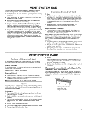
.... If Retractable Downdraft Vent Does Not Operate After Clean Filters Have Been Installed: Push the filter in dishwasher or hot detergent solution. 3. To Replace: 1. When Cooking Is Complete: 1. Pull the spring release handle down the filter. 2. Repeat steps 1-5 for the downdraft vent to the downdraft vent if water is already lit. B C A. Left metal filter C. Immediately turn the downdraft vent off the downdraft vent at the circuit breaker box or fuse box. 4. Do not use scouring powder...
.... If Retractable Downdraft Vent Does Not Operate After Clean Filters Have Been Installed: Push the filter in dishwasher or hot detergent solution. 3. To Replace: 1. When Cooking Is Complete: 1. Pull the spring release handle down the filter. 2. Repeat steps 1-5 for the downdraft vent to the downdraft vent if water is already lit. B C A. Left metal filter C. Immediately turn the downdraft vent off the downdraft vent at the circuit breaker box or fuse box. 4. Do not use scouring powder...
Owners Manual
Page 18
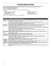
...-2692 Customer eXperience Centre Whirlpool Canada LP 200 - 6750 Century Ave. Is the downdraft correctly secured? Blower does not operate Is the vent fully raised? Blower Motor" section. Downdraft not level on the top of vent. Make sure both of the support legs have the same height from the Off position? Use stainless steel cleaner to start retracting. Is there noise due to activate the microswitch behind the filter. Are the filters installed...
...-2692 Customer eXperience Centre Whirlpool Canada LP 200 - 6750 Century Ave. Is the downdraft correctly secured? Blower does not operate Is the vent fully raised? Blower Motor" section. Downdraft not level on the top of vent. Make sure both of the support legs have the same height from the Off position? Use stainless steel cleaner to start retracting. Is there noise due to activate the microswitch behind the filter. Are the filters installed...
Owners Manual
Page 19
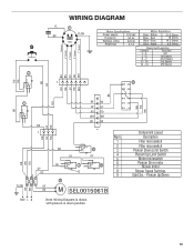
... Filter microswitch Filter microswitch Plenum Down Limit Switch Plenum Up Limit Switch Motor microswitch Plenum Drive motor Blower motor Blower Speed Switches Start Sw. - COM N.C. WIRING DIAGRAM YL 7 BR M YL/GN S50 Motor Specifications Power supply 120 VAC Frequency 60 Hz Wattage rating 420 W Amperage 3.7 A Motor Resistance Blue - White Blue - Red 21.6 Ohms 18 Ohms Blue - GY GY N.O. N.O. BR N.O. Plenum Up/Down 19 Black 9.8 Ohms Neutral 4° Speed 3° Speed 2° Speed 1° Speed 9 Blower Switch operation...
... Filter microswitch Filter microswitch Plenum Down Limit Switch Plenum Up Limit Switch Motor microswitch Plenum Drive motor Blower motor Blower Speed Switches Start Sw. - COM N.C. WIRING DIAGRAM YL 7 BR M YL/GN S50 Motor Specifications Power supply 120 VAC Frequency 60 Hz Wattage rating 420 W Amperage 3.7 A Motor Resistance Blue - White Blue - Red 21.6 Ohms 18 Ohms Blue - GY GY N.O. N.O. BR N.O. Plenum Up/Down 19 Black 9.8 Ohms Neutral 4° Speed 3° Speed 2° Speed 1° Speed 9 Blower Switch operation...
Owners Manual
Page 20
... replacement parts, we recommend that you use only factory specified parts. Accessories NOTE: Instructions are made with the same precision used to Whirlpool Canada LP with : ■■ Scheduling of appliances. ■■ Referrals to local dealers. ■■ Installation information. ■■ Use and maintenance procedures. ■■ Accessory and repair parts sales. ■■ Specialized customer assistance (Spanish-speaking, hearing-impaired, limited vision, etc.). Whirlpool-designated service...
... replacement parts, we recommend that you use only factory specified parts. Accessories NOTE: Instructions are made with the same precision used to Whirlpool Canada LP with : ■■ Scheduling of appliances. ■■ Referrals to local dealers. ■■ Installation information. ■■ Use and maintenance procedures. ■■ Accessory and repair parts sales. ■■ Specialized customer assistance (Spanish-speaking, hearing-impaired, limited vision, etc.). Whirlpool-designated service...
Owners Manual
Page 21
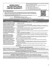
... Whirlpool Canada LP (hereafter "Whirlpool") will be borne by Whirlpool. In the U.S. ONE YEAR LIMITED WARRANTY WHAT IS COVERED WHAT IS NOT COVERED For one year from natural gas or L.P. instructions attached to access additional resources, or visit www.whirlpool.com/product_help. 2. house wiring, fuses or water inlet hoses). Cosmetic damage including scratches, dents, chips, and other than the limited warranty that interfere with original model/serial numbers removed...
... Whirlpool Canada LP (hereafter "Whirlpool") will be borne by Whirlpool. In the U.S. ONE YEAR LIMITED WARRANTY WHAT IS COVERED WHAT IS NOT COVERED For one year from natural gas or L.P. instructions attached to access additional resources, or visit www.whirlpool.com/product_help. 2. house wiring, fuses or water inlet hoses). Cosmetic damage including scratches, dents, chips, and other than the limited warranty that interfere with original model/serial numbers removed...

Owners Manual
Page 44
W10342491F ®/™ ©2016 Whirlpool. All rights reserved. Utilisé sous licence au Canada. Tous droits réservés. 12/16 Used under license in Canada.
W10342491F ®/™ ©2016 Whirlpool. All rights reserved. Utilisé sous licence au Canada. Tous droits réservés. 12/16 Used under license in Canada.


