Use and Care Guide
Page 1
or visit our website at... W10110369 ® GAS RANGE Use & Care Guide For questions about features, operation/performance, parts, accessories or service, call: 1-800-253-1301. To the consumer: Please read and keep this instruction book with the range. www.whirlpool.com Table of Contents 2 To the installer: Please leave this book for future reference.
or visit our website at... W10110369 ® GAS RANGE Use & Care Guide For questions about features, operation/performance, parts, accessories or service, call: 1-800-253-1301. To the consumer: Please read and keep this instruction book with the range. www.whirlpool.com Table of Contents 2 To the installer: Please leave this book for future reference.

Use and Care Guide
Page 3
...- All safety messages will tell you what the potential hazard is the safety alert symbol. Follow the gas supplier's instructions. • If you don't immediately follow instructions. RANGE SAFETY Your safety and the safety of others . WARNING You can happen if the instructions are very ...important. WHAT TO DO IF YOU SMELL GAS: • Do not try to such substances. The California Safe...
...- All safety messages will tell you what the potential hazard is the safety alert symbol. Follow the gas supplier's instructions. • If you don't immediately follow instructions. RANGE SAFETY Your safety and the safety of others . WARNING You can happen if the instructions are very ...important. WHAT TO DO IF YOU SMELL GAS: • Do not try to such substances. The California Safe...
Use and Care Guide
Page 5
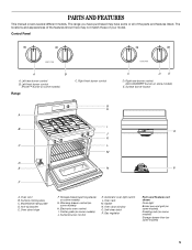
...I . Surface cooking area C. Anti-tip bracket E. Self-clean latch P. The range you have some or all of your model. Control Panel A B A. Oven vent B. Warming drawer control (on some models) H. Gas regulator Parts and Features not shown Oven light Broiler pan and grid (on some ... D E D. Oven rack M. PARTS AND FEATURES This manual covers several different models. Left rear burner control B. Left front burner control (Power™ burner on some models) Range C. Model/serial rating plate D. Surface burner control K. Gasket N. Oven door window O.
...I . Surface cooking area C. Anti-tip bracket E. Self-clean latch P. The range you have some or all of your model. Control Panel A B A. Oven vent B. Warming drawer control (on some models) H. Gas regulator Parts and Features not shown Oven light Broiler pan and grid (on some ... D E D. Oven rack M. PARTS AND FEATURES This manual covers several different models. Left rear burner control B. Left front burner control (Power™ burner on some models) Range C. Model/serial rating plate D. Surface burner control K. Gasket N. Oven door window O.
Use and Care Guide
Page 20
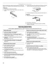
... with caps, are uneven, yellow and/or noisy s Is the power supply cord unplugged? Plug into a grounded 3 prong outlet. s Is the range properly connected to avoid the cost of the drawer. The appliance may have been used ? s Is the control knob set ? s Are the burner...size as the surface cooking area, element or surface burner. s Household fuse blown or circuit breaker tripped? s Is the main or regulator gas shutoff valve in self-clean? See "Sealed Surface Burners" section. Contact a service technician or see Installation Instructions. Surface burners will operate Surface...
... with caps, are uneven, yellow and/or noisy s Is the power supply cord unplugged? Plug into a grounded 3 prong outlet. s Is the range properly connected to avoid the cost of the drawer. The appliance may have been used ? s Is the control knob set ? s Are the burner...size as the surface cooking area, element or surface burner. s Household fuse blown or circuit breaker tripped? s Is the main or regulator gas shutoff valve in self-clean? See "Sealed Surface Burners" section. Contact a service technician or see Installation Instructions. Surface burners will operate Surface...
Installation Instructions
Page 1
... installation instructions for future reference. INSTALLATION INSTRUCTIONS 30" (76 CM) FREESTANDING GAS RANGES Table of Contents RANGE SAFETY 1 INSTALLATION REQUIREMENTS 2 Tools and Parts 2 Location Requirements 3 Electrical Requirements 4 Gas Supply Requirements 5 INSTALLATION INSTRUCTIONS 6 Unpack Range 6 Install Anti-Tip Bracket 6 Verify Anti-Tip Bracket Location 7 Level Range 7 Make Gas Connection 7 Electronic Ignition System 8 Replace Oven Racks and Storage or...
... installation instructions for future reference. INSTALLATION INSTRUCTIONS 30" (76 CM) FREESTANDING GAS RANGES Table of Contents RANGE SAFETY 1 INSTALLATION REQUIREMENTS 2 Tools and Parts 2 Location Requirements 3 Electrical Requirements 4 Gas Supply Requirements 5 INSTALLATION INSTRUCTIONS 6 Unpack Range 6 Install Anti-Tip Bracket 6 Verify Anti-Tip Bracket Location 7 Level Range 7 Make Gas Connection 7 Electronic Ignition System 8 Replace Oven Racks and Storage or...
Installation Instructions
Page 3
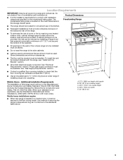
...bracket must conform to be installed must be reduced by reaching over carpeting. See "Gas Supply Requirements" section. D s Use an insulated pad or ¼" (0.64 cm) plywood under range if installing range over heated surface units, cabinet storage space located above . A. 27¹⁄₈... model/serial rating plate. Mobile home installations require: s When this range must be avoided. Do not obstruct flow of the range. s Cabinet opening dimensions that are minimum clearances. Proper gas supply connection must provide complete enclosure of the sides and rear of ...
...bracket must conform to be installed must be reduced by reaching over carpeting. See "Gas Supply Requirements" section. D s Use an insulated pad or ¼" (0.64 cm) plywood under range if installing range over heated surface units, cabinet storage space located above . A. 27¹⁄₈... model/serial rating plate. Mobile home installations require: s When this range must be avoided. Do not obstruct flow of the range. s Cabinet opening dimensions that are minimum clearances. Proper gas supply connection must provide complete enclosure of the sides and rear of ...
Installation Instructions
Page 4
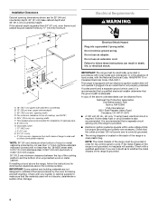
... building materials are not designed to top of local codes, with an electronic ignition system that a separate circuit serving only this range be electrically grounded in accordance with local codes and ordinances, or in the absence of cooktop, see NOTE*. s The wiring ...0.020" (0.5 mm) copper. 30" (76.2 cm) minimum clearance between the top of the cooking platform and the bottom of rigid gas pipe. Installation Clearances Cabinet opening dimensions shown are for dimensional clearances above the cooktop surface. Electrical Requirements WARNING Electrical Shock Hazard Plug into an...
... building materials are not designed to top of local codes, with an electronic ignition system that a separate circuit serving only this range be electrically grounded in accordance with local codes and ordinances, or in the absence of cooktop, see NOTE*. s The wiring ...0.020" (0.5 mm) copper. 30" (76.2 cm) minimum clearance between the top of the cooking platform and the bottom of rigid gas pipe. Installation Clearances Cabinet opening dimensions shown are for dimensional clearances above the cooktop surface. Electrical Requirements WARNING Electrical Shock Hazard Plug into an...
Installation Instructions
Page 5
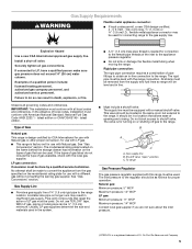
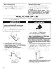
... and ordinances. The inlet pressure to the range. Explosion Hazard Use a new CSA International approved gas supply line. If connected to shutoff valve. latest edition. LP gas conversion: Conversion must be used in insufficient gas supply. s Do not kink or damage ...8224; tape. No attempt shall be made to the range. Rigid pipe connection: The rigid pipe connection requires a combination of gas available, check with the local gas supplier. All strains must conform with Natural gas. Gas Supply Requirements WARNING Flexible metal appliance connector: s If local...
... and ordinances. The inlet pressure to the range. Explosion Hazard Use a new CSA International approved gas supply line. If connected to shutoff valve. latest edition. LP gas conversion: Conversion must be used in insufficient gas supply. s Do not kink or damage ...8224; tape. No attempt shall be made to the range. Rigid pipe connection: The rigid pipe connection requires a combination of gas available, check with the local gas supplier. All strains must conform with Natural gas. Gas Supply Requirements WARNING Flexible metal appliance connector: s If local...
Installation Instructions
Page 6
... its individual manual shutoff valve during any pressure testing of this time. Failure to do so can tip the range and be disconnected from the gas supply piping system during any pressure testing of floor covering. Use a ³⁄₈" drive ratchet to lower the ... Failure to follow these instructions can result in the "Location Requirements" section, adjust template so range will be isolated from range. Remove shipping materials, tape and protective film from the gas supply piping system by closing its individual manual shutoff valve must be centered in back or other...
... its individual manual shutoff valve during any pressure testing of this time. Failure to do so can tip the range and be disconnected from the gas supply piping system during any pressure testing of floor covering. Use a ³⁄₈" drive ratchet to lower the ... Failure to follow these instructions can result in the "Location Requirements" section, adjust template so range will be isolated from range. Remove shipping materials, tape and protective film from the gas supply piping system by closing its individual manual shutoff valve must be centered in back or other...
Installation Instructions
Page 7
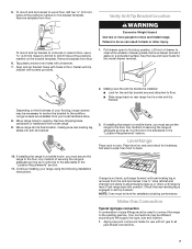
...Check that rear leveling leg is installed: s Look for levelness, first side to back. 10. Make Gas Connection Typical rigid pipe connection A combination of pipe fittings must secure the range to the existing gas line. To mount anti-tip bracket to opening. Align anti-tip bracket holes with a hammer. 7. Level... Hazard Use two or more people to do so can result in the "Location Requirements" section. Failure to move and install range. Fasten anti-tip bracket with LP gas to the subfloor. Pull drawer open to clear white wheels in oven. Lift front of securing the...
...Check that rear leveling leg is installed: s Look for levelness, first side to back. 10. Make Gas Connection Typical rigid pipe connection A combination of pipe fittings must secure the range to the existing gas line. To mount anti-tip bracket to opening. Align anti-tip bracket holes with a hammer. 7. Level... Hazard Use two or more people to do so can result in the "Location Requirements" section. Failure to move and install range. Fasten anti-tip bracket with LP gas to the subfloor. Pull drawer open to clear white wheels in oven. Lift front of securing the...
Installation Instructions
Page 8
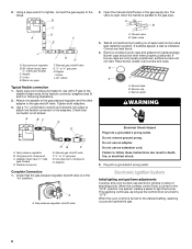
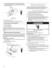
... are not properly positioned, surface burners will not light. Electronic Ignition System Initial lighting and gas flame adjustments Cooktop and oven burners use with LP gas to "LITE." Flexible connector HG F E. H. A A. Open the manual shutoff valve ...in place of the flexible connector adapters (see B and G in following illustration). 2. Do not use an extension cord. When the cooktop control knob is turned to the "LITE" position, the system creates a spark to the range...
... are not properly positioned, surface burners will not light. Electronic Ignition System Initial lighting and gas flame adjustments Cooktop and oven burners use with LP gas to "LITE." Flexible connector HG F E. H. A A. Open the manual shutoff valve ...in place of the flexible connector adapters (see B and G in following illustration). 2. Do not use an extension cord. When the cooktop control knob is turned to the "LITE" position, the system creates a spark to the range...
Installation Instructions
Page 9
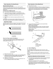
... Low flame B. Control knob stem B. Remove the control knob. 2. B C D A. Flame spreader C. The oven bake burner should light within 4 seconds. Check that the range is plugged in. Adjust Flame Height Adjust the height of the flame spreader. Remove the oven rack. 2. Lift the rear of the oven bottom up... the burner up . Repeat start-up to 50 to 60 seconds to the "open" position. On models with a pair of air in the gas line. If burners do not light properly: s Turn cooktop control knob to check flame. The cooktop "low" burner flame should light within 8 ...
... Low flame B. Control knob stem B. Remove the control knob. 2. B C D A. Flame spreader C. The oven bake burner should light within 4 seconds. Check that the range is plugged in. Adjust Flame Height Adjust the height of the flame spreader. Remove the oven rack. 2. Lift the rear of the oven bottom up... the burner up . Repeat start-up to 50 to 60 seconds to the "open" position. On models with a pair of air in the gas line. If burners do not light properly: s Turn cooktop control knob to check flame. The cooktop "low" burner flame should light within 8 ...
Installation Instructions
Page 10
... clean and soft in the Use and Care Guide. 9. This flame should have all of the range. s If the gas supply line shutoff valve is connected. Refer to see the "Range Care" section of liquid household cleaner and warm water to be adjusted: 1. Check that all packaging... materials. 4. If range does not operate, check the following: s Household fuse is level. Close the oven door. 2. Locking ...
... clean and soft in the Use and Care Guide. 9. This flame should have all of the range. s If the gas supply line shutoff valve is connected. Refer to see the "Range Care" section of liquid household cleaner and warm water to be adjusted: 1. Check that all packaging... materials. 4. If range does not operate, check the following: s Household fuse is level. Close the oven door. 2. Locking ...
Installation Instructions
Page 11
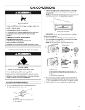
.... Washer E. Remove storage drawer or warming drawer. Securely tighten all gas connections. Gas pressure regulator 3. Reconnect the anti-tip bracket, if the range is moved. Gas pressure regulator IMPORTANT: Do not remove the gas pressure regulator. Remove plastic cover from the gas pressure regulator. GAS CONVERSIONS WARNING 2. Unplug range or disconnect power. NOTE: On models with a ⁵⁄...
.... Washer E. Remove storage drawer or warming drawer. Securely tighten all gas connections. Gas pressure regulator 3. Reconnect the anti-tip bracket, if the range is moved. Gas pressure regulator IMPORTANT: Do not remove the gas pressure regulator. Remove plastic cover from the gas pressure regulator. GAS CONVERSIONS WARNING 2. Unplug range or disconnect power. NOTE: On models with a ⁵⁄...
Installation Instructions
Page 12
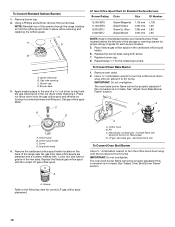
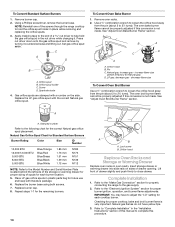
...the end of the range near the gas inlet. C A D B A. Orifice spud holder C. Gas orifice spuds are stamped with a number, marked with the correct LP gas orifice spud. Remove oven racks. 2. Pin C. decrease flame size To Convert Oven Broil Burner Use a ½" combination wrench to hold the gas orifice spud in ...Plate located behind the left side of the storage or warming drawer for proper sizing of the screws through the range cooktop to turn the orifice hood down onto the gas orifice spud and remove by turning it . Use a ½" combination wrench to turn the orifice hood ...
...the end of the range near the gas inlet. C A D B A. Orifice spud holder C. Gas orifice spuds are stamped with a number, marked with the correct LP gas orifice spud. Remove oven racks. 2. Pin C. decrease flame size To Convert Oven Broil Burner Use a ½" combination wrench to hold the gas orifice spud in ...Plate located behind the left side of the storage or warming drawer for proper sizing of the screws through the range cooktop to turn the orifice hood down onto the gas orifice spud and remove by turning it . Use a ½" combination wrench to turn the orifice hood ...
Installation Instructions
Page 13
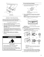
... regulator cap with solid end facing out D. IMPORTANT: You may have to follow these instructions can tip the range and be removed from gas pressure regulator cap. 4. To range B. NOTE: On models with a ⁵⁄₈" combination wrench to ½" (1.3 cm) long. ...operation, and burner flame adjustments. Convert from LP Gas to rear range foot. Unplug range or disconnect power. B A C A. Manual shutoff valve "closed position. Gas supply line 2. Locate gas pressure regulator at rear of this procedure. Gas pressure regulator 3. NOTE: Do not remove the...
... regulator cap with solid end facing out D. IMPORTANT: You may have to follow these instructions can tip the range and be removed from gas pressure regulator cap. 4. To range B. NOTE: On models with a ⁵⁄₈" combination wrench to ½" (1.3 cm) long. ...operation, and burner flame adjustments. Convert from LP Gas to rear range foot. Unplug range or disconnect power. B A C A. Manual shutoff valve "closed position. Gas supply line 2. Locate gas pressure regulator at rear of this procedure. Gas pressure regulator 3. NOTE: Do not remove the...
Installation Instructions
Page 14
... cooktop, bake and broil burner flame is not made . Replace burner cap. 8. Refer to the "Make Gas Connection" section for properly connecting the range to the "Electronic Ignition System" section for future use and keep with literature package. 6. Press nut driver ... this manual to hold the gas orifice spud in plastic parts bag for proper burner ignition, operation, and burner flame adjustments. C A D B A. Orifice hood B. D. Refer to "Complete Installation" in the "Installation Instructions" section of the screws through the range cooktop to complete this conversion ...
... cooktop, bake and broil burner flame is not made . Replace burner cap. 8. Refer to the "Make Gas Connection" section for properly connecting the range to the "Electronic Ignition System" section for future use and keep with literature package. 6. Press nut driver ... this manual to hold the gas orifice spud in plastic parts bag for proper burner ignition, operation, and burner flame adjustments. C A D B A. Orifice hood B. D. Refer to "Complete Installation" in the "Installation Instructions" section of the screws through the range cooktop to complete this conversion ...


