Use and Care Guide
Page 6
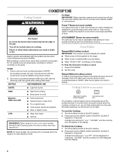
...when setting heat levels. s Cook soups, sauces and gravies. Night light/cooktop lockout keypad Cooktop lockout icon The Cooktop Lockout helps to IGNITE. Press and hold the NIGHT LIGHT/COOKTOP LOCKOUT keypad for 3 seconds. Press and hold the NIGHT LIGHT/COOKTOP LOCKOUT keypad for 3 ... all controls when not cooking. Power™ Burner (on some models) The right front burner or both front burners (on . Electric igniters automatically light the surface burners when control knobs are designed to setting. Before setting a control knob, place filled cookware on the grate. ...
...when setting heat levels. s Cook soups, sauces and gravies. Night light/cooktop lockout keypad Cooktop lockout icon The Cooktop Lockout helps to IGNITE. Press and hold the NIGHT LIGHT/COOKTOP LOCKOUT keypad for 3 seconds. Press and hold the NIGHT LIGHT/COOKTOP LOCKOUT keypad for 3 ... all controls when not cooking. Power™ Burner (on some models) The right front burner or both front burners (on . Electric igniters automatically light the surface burners when control knobs are designed to setting. Before setting a control knob, place filled cookware on the grate. ...
Use and Care Guide
Page 7
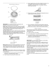
.... Aluminum and copper may scratch the cooktop or grates. Do not enlarge or distort the port. Do not use oven cleaners, bleach or rust removers. 1. Igniter E. Correct 5. s For more information, contact your local agricultural department. B A. 1-1¹⁄₂" (25-38 mm) B. To Clean: IMPORTANT: Before cleaning, make sure all controls are...
.... Aluminum and copper may scratch the cooktop or grates. Do not enlarge or distort the port. Do not use oven cleaners, bleach or rust removers. 1. Igniter E. Correct 5. s For more information, contact your local agricultural department. B A. 1-1¹⁄₂" (25-38 mm) B. To Clean: IMPORTANT: Before cleaning, make sure all controls are...
Installation Instructions
Page 1
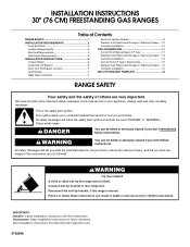
... Requirements 3 Electrical Requirements 4 Gas Supply Requirements 5 INSTALLATION INSTRUCTIONS 6 Unpack Range 6 Install Anti-Tip Bracket 6 Verify Anti-Tip Bracket Location 7 Level Range 7 Make Gas Connection 7 Electronic Ignition System 8 Replace Oven Racks and Storage or Warming Drawer ... 10 Complete Installation 10 GAS CONVERSIONS 11 Convert from Natural Gas to LP Gas 11 Replace...
... Requirements 3 Electrical Requirements 4 Gas Supply Requirements 5 INSTALLATION INSTRUCTIONS 6 Unpack Range 6 Install Anti-Tip Bracket 6 Verify Anti-Tip Bracket Location 7 Level Range 7 Make Gas Connection 7 Electronic Ignition System 8 Replace Oven Racks and Storage or Warming Drawer ... 10 Complete Installation 10 GAS CONVERSIONS 11 Convert from Natural Gas to LP Gas 11 Replace...
Installation Instructions
Page 4
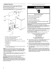
..., CSA C22.1. This range is equipped with not less than ¹⁄₄" (0.64 cm) flame retardant millboard covered with an electronic ignition system that is grounded. 4 G. 8" (20.3 cm) H. s Electronic ignition systems operate within wide voltage limits, but proper grounding and polarity are necessary. s The wiring diagram is also recommended. opening width...
..., CSA C22.1. This range is equipped with not less than ¹⁄₄" (0.64 cm) flame retardant millboard covered with an electronic ignition system that is grounded. 4 G. 8" (20.3 cm) H. s Electronic ignition systems operate within wide voltage limits, but proper grounding and polarity are necessary. s The wiring diagram is also recommended. opening width...
Installation Instructions
Page 8
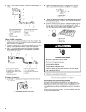
..., surface burners will not light. Burner grate WARNING Electrical Shock Hazard Plug into a grounded 3 prong outlet. Electronic Ignition System Initial lighting and gas flame adjustments Cooktop and oven burners use with LP gas to the desired setting, sparking occurs and...176; elbow (must have ½" male pipe thread) C. Nipple D. Union E. Black iron pipe I . Apply pipe-joint compound made for use electronic igniters in place of the flexible connector adapters (see B and G in the "on an approved noncorrosive leak-detection solution. Tighten both adapters. 3. Gas pressure...
..., surface burners will not light. Burner grate WARNING Electrical Shock Hazard Plug into a grounded 3 prong outlet. Electronic Ignition System Initial lighting and gas flame adjustments Cooktop and oven burners use with LP gas to the desired setting, sparking occurs and...176; elbow (must have ½" male pipe thread) C. Nipple D. Union E. Black iron pipe I . Apply pipe-joint compound made for use electronic igniters in place of the flexible connector adapters (see B and G in the "on an approved noncorrosive leak-detection solution. Tighten both adapters. 3. Gas pressure...
Installation Instructions
Page 9
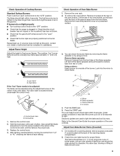
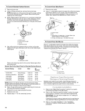
.... 2. On models with a pair of pliers. Screwdriver 1. B C D A. Look into the mirror to the "OFF" position. The cooktop "low" burner flame should light within 4 seconds. Electronic igniters are set to light because of air in the center of the valve stem. Adjust Oven Bake Burner Flame (if needed) 1. You can be adjusted...
.... 2. On models with a pair of pliers. Screwdriver 1. B C D A. Look into the mirror to the "OFF" position. The cooktop "low" burner flame should light within 4 seconds. Electronic igniters are set to light because of air in the center of the valve stem. Adjust Oven Bake Burner Flame (if needed) 1. You can be adjusted...
Installation Instructions
Page 12
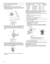
... 0.80 mm 0.65 mm L103 L99 L80 L65 NOTE: Refer to the following chart for Natural gas) D. See "Adjust Oven Bake Burner Flame" section. Pin C. Igniter electrode B.
... 0.80 mm 0.65 mm L103 L99 L80 L65 NOTE: Refer to the following chart for Natural gas) D. See "Adjust Oven Bake Burner Flame" section. Pin C. Igniter electrode B.
Installation Instructions
Page 13
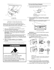
...or warming drawer compartment. Refer to the closed " position C. Checking for each cooktop burner. Turn the manual shutoff valve to the "Electronic Ignition System" section for properly connecting the range to rear range foot. B A C A. Gas pressure regulator IMPORTANT: Do not remove the gas... out C. Gas pressure regulator 3. Plastic cover B. Gas pressure regulator cap 5. Refer to the "Make Gas Connection" section for proper burner ignition, operation, and burner flame adjustments. IMPORTANT: You may have a slightly yellow tip. 3. LP gas flames have to close drawer. Unplug range...
...or warming drawer compartment. Refer to the closed " position C. Checking for each cooktop burner. Turn the manual shutoff valve to the "Electronic Ignition System" section for properly connecting the range to rear range foot. B A C A. Gas pressure regulator IMPORTANT: Do not remove the gas... out C. Gas pressure regulator 3. Plastic cover B. Gas pressure regulator cap 5. Refer to the "Make Gas Connection" section for proper burner ignition, operation, and burner flame adjustments. IMPORTANT: You may have a slightly yellow tip. 3. LP gas flames have to close drawer. Unplug range...
Installation Instructions
Page 14
... a ½" combination wrench to loosen the orifice hood away from the pin (about 2 to adjust the "LO" setting for proper burner ignition, operation, and burner flame adjustments. See "Adjust Oven Broil Burner Flame" section. Repeat steps 1-7 for Natural gas). Complete Installation 1. IMPORTANT:...replacing the orifice spuds. 3. Refer to close drawer. Apply masking tape to the end of drawer slightly and push firmly to the "Electronic Ignition System" section for each burner location. 5. See "Adjust Oven Bake Burner Flame" section. Stamped number Refer to the gas supply. 2....
... a ½" combination wrench to loosen the orifice hood away from the pin (about 2 to adjust the "LO" setting for proper burner ignition, operation, and burner flame adjustments. See "Adjust Oven Broil Burner Flame" section. Repeat steps 1-7 for Natural gas). Complete Installation 1. IMPORTANT:...replacing the orifice spuds. 3. Refer to close drawer. Apply masking tape to the end of drawer slightly and push firmly to the "Electronic Ignition System" section for each burner location. 5. See "Adjust Oven Bake Burner Flame" section. Stamped number Refer to the gas supply. 2....

