Use and Care Guide
Page 1
W10110369 ® GAS RANGE Use & Care Guide For questions about features, operation/performance, parts, accessories or service, call: 1-800-253-1301. or visit our website at... www.whirlpool.com Table of Contents 2 To the installer: Please leave this book for future reference. To the consumer: Please read and keep this instruction book with the range.
W10110369 ® GAS RANGE Use & Care Guide For questions about features, operation/performance, parts, accessories or service, call: 1-800-253-1301. or visit our website at... www.whirlpool.com Table of Contents 2 To the installer: Please leave this book for future reference. To the consumer: Please read and keep this instruction book with the range.

Use and Care Guide
Page 3
RANGE SAFETY Your safety and the safety of this or any phone in your building. • Immediately call the fire department. - Always read and obey all safety messages. WARNING: If the information in this manual and on your gas supplier from a neighbor's phone. Follow the gas supplier's instructions...may result causing property damage, personal injury or death. - WARNING You can be killed or seriously injured if you cannot reach your gas supplier, call your appliance. Do not store or use any other appliance. - The California Safe Drinking Water and Toxic Enforcement Act ...
RANGE SAFETY Your safety and the safety of this or any phone in your building. • Immediately call the fire department. - Always read and obey all safety messages. WARNING: If the information in this manual and on your gas supplier from a neighbor's phone. Follow the gas supplier's instructions...may result causing property damage, personal injury or death. - WARNING You can be killed or seriously injured if you cannot reach your gas supplier, call your appliance. Do not store or use any other appliance. - The California Safe Drinking Water and Toxic Enforcement Act ...
Use and Care Guide
Page 5
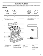
... on some models) 5 Center grate (on some models) Range C. Oven rack M. Self-clean latch P. Right front burner control G H A I . Automatic oven light switch L. Oven door window O. Gas regulator Parts and Features not shown Oven light Broiler pan and...D. Control Panel A B A. Model/serial rating plate D. Right rear burner control (ACCUSIMMER® burner on some or all of your model. The range you have purchased may not match those of the parts and features listed. Gasket N. PARTS AND FEATURES This manual covers several different models. Oven vent ...
... on some models) 5 Center grate (on some models) Range C. Oven rack M. Self-clean latch P. Right front burner control G H A I . Automatic oven light switch L. Oven door window O. Gas regulator Parts and Features not shown Oven light Broiler pan and...D. Control Panel A B A. Model/serial rating plate D. Right rear burner control (ACCUSIMMER® burner on some or all of your model. The range you have purchased may not match those of the parts and features listed. Gasket N. PARTS AND FEATURES This manual covers several different models. Oven vent ...
Use and Care Guide
Page 20
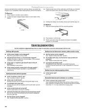
...) Remove all items from the gas lines. Open drawer to its sides, slowly pull it dry. Locate the black triangle-shaped tabs on any one of the surface burner knobs to release air from inside the warming drawer, and allow the range to cool completely before turning to... avoid the cost of the drawer. Push drawer in self-clean? TROUBLESHOOTING Try the solutions suggested here first in order to a setting. Plug into a grounded 3 prong outlet. See Installation Instructions. s Is propane gas being used ? See "Cooktop...
...) Remove all items from the gas lines. Open drawer to its sides, slowly pull it dry. Locate the black triangle-shaped tabs on any one of the surface burner knobs to release air from inside the warming drawer, and allow the range to cool completely before turning to... avoid the cost of the drawer. Push drawer in self-clean? TROUBLESHOOTING Try the solutions suggested here first in order to a setting. Plug into a grounded 3 prong outlet. See Installation Instructions. s Is propane gas being used ? See "Cooktop...
Installation Instructions
Page 1
... manual and on your appliance. INSTALLATION INSTRUCTIONS 30" (76 CM) FREESTANDING GAS RANGES Table of Contents RANGE SAFETY 1 INSTALLATION REQUIREMENTS 2 Tools and Parts 2 Location Requirements 3 Electrical Requirements 4 Gas Supply Requirements 5 INSTALLATION INSTRUCTIONS 6 Unpack Range 6 Install Anti-Tip Bracket 6 Verify Anti-Tip Bracket Location 7 Level Range 7 Make Gas Connection 7 Electronic Ignition System 8 Replace Oven Racks and Storage or...
... manual and on your appliance. INSTALLATION INSTRUCTIONS 30" (76 CM) FREESTANDING GAS RANGES Table of Contents RANGE SAFETY 1 INSTALLATION REQUIREMENTS 2 Tools and Parts 2 Location Requirements 3 Electrical Requirements 4 Gas Supply Requirements 5 INSTALLATION INSTRUCTIONS 6 Unpack Range 6 Install Anti-Tip Bracket 6 Verify Anti-Tip Bracket Location 7 Level Range 7 Make Gas Connection 7 Electronic Ignition System 8 Replace Oven Racks and Storage or...
Installation Instructions
Page 3
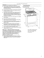
.... Additional Installation Requirements The installation of this range is to the floor during transit. If cabinet storage is installed in the kitchen. See "Gas Supply Requirements" section. Product Dimensions Freestanding Range s The range should be reduced by reaching over carpeting. ...s Do not seal the range to comply with the range, see "Install Anti-Tip Bracket" section. Mobile home installations require: s When this range must ...
.... Additional Installation Requirements The installation of this range is to the floor during transit. If cabinet storage is installed in the kitchen. See "Gas Supply Requirements" section. Product Dimensions Freestanding Range s The range should be reduced by reaching over carpeting. ...s Do not seal the range to comply with the range, see "Install Anti-Tip Bracket" section. Mobile home installations require: s When this range must ...
Installation Instructions
Page 4
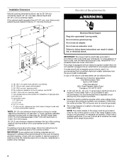
...8260;₈" (76.5 cm) min. This shaded area recommended for installation of the above the range, follow these instructions can be electrically grounded in death, fire, or electrical shock. A copy of rigid gas pipe. NOTE: The metal chassis of cooktop, see NOTE*. If the cabinet depth is equipped with... a qualified electrician if you are necessary. Do not use an adapter. Failure to top of the range must extend beyond cabinet fronts by the ...
...8260;₈" (76.5 cm) min. This shaded area recommended for installation of the above the range, follow these instructions can be electrically grounded in death, fire, or electrical shock. A copy of rigid gas pipe. NOTE: The metal chassis of cooktop, see NOTE*. If the cabinet depth is equipped with... a qualified electrician if you are necessary. Do not use an adapter. Failure to top of the range must extend beyond cabinet fronts by the ...
Installation Instructions
Page 5
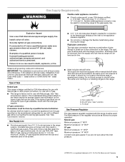
.... Do not block access to the appliance pressure regulator. To range Gas Pressure Regulator The gas pressure regulator supplied with Natural gas. s This range is for turning on longer runs may be used for connecting range to the regulator should be done by CSA International for use ...to the female pipe threads of gas available, check with all local codes and ordinances. Gas supply line B. Du Pont De Nemours and Company. 5 Gas Supply Line s Provide a gas supply line of Gas Natural gas: This range is needed for proper operation: Natural gas: Minimum pressure: 5" WCP Maximum...
.... Do not block access to the appliance pressure regulator. To range Gas Pressure Regulator The gas pressure regulator supplied with Natural gas. s This range is for turning on longer runs may be used for connecting range to the regulator should be done by CSA International for use ...to the female pipe threads of gas available, check with all local codes and ordinances. Gas supply line B. Du Pont De Nemours and Company. 5 Gas Supply Line s Provide a gas supply line of Gas Natural gas: This range is needed for proper operation: Natural gas: Minimum pressure: 5" WCP Maximum...
Installation Instructions
Page 6
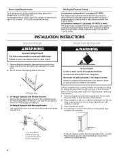
... at ½ psi gauge (14" WCP) or lower The range must be isolated from the gas supply piping system by closing its individual manual shutoff valve must be disconnected from the back of floor covering. Failure to rear range foot. Install Anti-Tip Bracket WARNING 1. Do not remove the ... and protective film from inside the oven cavity) or from the gas supply piping system during any pressure testing of that the left edge is against rear wall, molding or cabinet. 3. Remove oven racks and parts package from range. On Ranges Equipped with overhang. A D C Tip Over Hazard A child or...
... at ½ psi gauge (14" WCP) or lower The range must be isolated from the gas supply piping system by closing its individual manual shutoff valve must be disconnected from the back of floor covering. Failure to rear range foot. Install Anti-Tip Bracket WARNING 1. Do not remove the ... and protective film from inside the oven cavity) or from the gas supply piping system during any pressure testing of that the left edge is against rear wall, molding or cabinet. 3. Remove oven racks and parts package from range. On Ranges Equipped with overhang. A D C Tip Over Hazard A child or...
Installation Instructions
Page 7
...to the floor. NOTE: Oven must secure the range to floor. Your connections may be used to connect the range to concrete or ceramic floor, use with screws provided. 1. To mount anti-tip bracket to the existing gas line. s Slide range back so rear range foot is installed: s Look for use a... 4.8 mm) masonry drill bit to the subfloor. If installing the range in a mobile home, you must be necessary to anchor the bracket to ...
...to the floor. NOTE: Oven must secure the range to floor. Your connections may be used to connect the range to concrete or ceramic floor, use with screws provided. 1. To mount anti-tip bracket to the existing gas line. s Slide range back so rear range foot is installed: s Look for use a... 4.8 mm) masonry drill bit to the subfloor. If installing the range in a mobile home, you must be necessary to anchor the bracket to ...
Installation Instructions
Page 8
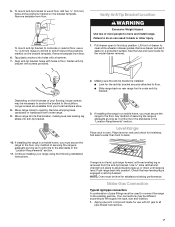
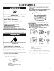
... H. Apply pipe-joint compound made for use electronic igniters in following illustration). 2. Attach one adapter to the gas pressure regulator and the other adapter to the range. Tighten both adapters. 3. Gas pressure regulator B. Flexible connector HG F E. Closed valve B. Burner caps should be level when properly positioned. Burner cap C. Do not use an extension...
... H. Apply pipe-joint compound made for use electronic igniters in following illustration). 2. Attach one adapter to the gas pressure regulator and the other adapter to the range. Tighten both adapters. 3. Gas pressure regulator B. Flexible connector HG F E. Closed valve B. Burner caps should be level when properly positioned. Burner cap C. Do not use an extension...
Installation Instructions
Page 9
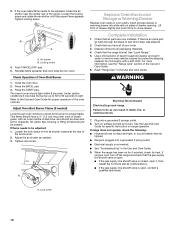
If burners do not light properly: s Turn cooktop control knob to the "open" position. Check that the range is plugged in. s Check that the gas shutoff valves are set to the "OFF" position. Lift the rear of the oven bottom up and back until the flame is the proper size. 3. ... of bluish-green, with an outer mantle of the flame spreader. A A. High flame If the "low" flame needs to light because of air in the gas line. Remove the control knob. 2. On models with a pair of pliers. This flame should be adjusted: The flame can check the burner flame by removing...
If burners do not light properly: s Turn cooktop control knob to the "open" position. Check that the range is plugged in. s Check that the gas shutoff valves are set to the "OFF" position. Lift the rear of the oven bottom up and back until the flame is the proper size. 3. ... of bluish-green, with an outer mantle of the flame spreader. A A. High flame If the "low" flame needs to light because of air in the gas line. Remove the control knob. 2. On models with a pair of pliers. This flame should be adjusted: The flame can check the burner flame by removing...
Installation Instructions
Page 10
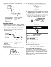
...recycle all packaging materials. 4. Tighten lock screw. Complete Installation 1. Check that the gas supply line shutoff valve is an extra part, go back through oven window to close drawer. WARNING Electrical Shock Hazard Electrically ground range. If range does not operate, check the following: s Household fuse is level. A. Tighten .... The oven burner should be clean and soft in the Use and Care Guide. Failure to see the "Range Care" section of the broil burner. 2. s If the gas supply line shutoff valve is closed, open it may take the burner up to 50 to 60 seconds to ...
...recycle all packaging materials. 4. Tighten lock screw. Complete Installation 1. Check that the gas supply line shutoff valve is an extra part, go back through oven window to close drawer. WARNING Electrical Shock Hazard Electrically ground range. If range does not operate, check the following: s Household fuse is level. A. Tighten .... The oven burner should be clean and soft in the Use and Care Guide. Failure to see the "Range Care" section of the broil burner. 2. s If the gas supply line shutoff valve is closed, open it may take the burner up to 50 to 60 seconds to ...
Installation Instructions
Page 11
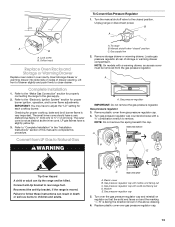
... drawer, an access cover must be killed. Unplug range or disconnect power. Gas pressure regulator cap with hollow end facing out D. If connected to LP Gas WARNING A A. To range B. Gas pressure regulator cap with solid end facing out C. Gas pressure regulator 3. Plastic cover B. Failure to do ...anti-tip bracket to follow these instructions can tip the range and be removed from gas pressure regulator cap. 4. Failure to rear range foot. Gas supply line C Side view after A. Reconnect the anti-tip bracket, if the range is moved. NOTE: Do not remove the spring beneath...
... drawer, an access cover must be killed. Unplug range or disconnect power. Gas pressure regulator cap with hollow end facing out D. If connected to LP Gas WARNING A A. To range B. Gas pressure regulator cap with solid end facing out C. Gas pressure regulator 3. Plastic cover B. Failure to do ...anti-tip bracket to follow these instructions can tip the range and be removed from gas pressure regulator cap. 4. Failure to rear range foot. Gas supply line C Side view after A. Reconnect the anti-tip bracket, if the range is moved. NOTE: Do not remove the spring beneath...
Installation Instructions
Page 12
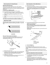
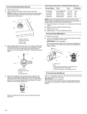
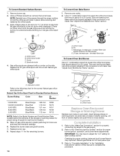
... base. NOTE: Reinstall one of a nut driver to hold the gas orifice spud in place while removing and replacing the orifice spuds. Burner cap D. Apply masking tape to the end of the screws through the range cooktop to help hold the orifice spud holder in the nut driver ... C A D B A. Orifice spud B. Remove the cardboard orifice spud holder located on the back of spuds for proper sizing of the range near the gas inlet. Place Natural gas orifice spuds in the hex area. To Convert Oven Bake Burner 1. The oven bake burner flame cannot be properly adjusted if this conversion...
... base. NOTE: Reinstall one of a nut driver to hold the gas orifice spud in place while removing and replacing the orifice spuds. Burner cap D. Apply masking tape to the end of the screws through the range cooktop to help hold the orifice spud holder in the nut driver ... C A D B A. Orifice spud B. Remove the cardboard orifice spud holder located on the back of spuds for proper sizing of the range near the gas inlet. Place Natural gas orifice spuds in the hex area. To Convert Oven Bake Burner 1. The oven bake burner flame cannot be properly adjusted if this conversion...
Installation Instructions
Page 13
...into slide rails on regulator so that the solid end faces out and the marking " Convert from LP Gas to the "Electronic Ignition System" section for each cooktop burner. Unplug range or disconnect power. Manual shutoff valve "closed position. Remove storage drawer or warming drawer. A A. ...broil burner flame is moved. Checking for properly connecting the range to "Complete Installation" in oven cavity. The outer cone is not as distinct as the inner cone. Refer to the gas supply. 2. Gas supply line 2. Turn gas pressure regulator cap counterclockwise with a warming drawer, an access ...
...into slide rails on regulator so that the solid end faces out and the marking " Convert from LP Gas to the "Electronic Ignition System" section for each cooktop burner. Unplug range or disconnect power. Manual shutoff valve "closed position. Remove storage drawer or warming drawer. A A. ...broil burner flame is moved. Checking for properly connecting the range to "Complete Installation" in oven cavity. The outer cone is not as distinct as the inner cone. Refer to the gas supply. 2. Gas supply line 2. Turn gas pressure regulator cap counterclockwise with a warming drawer, an access ...
Installation Instructions
Page 14
... slide rails on the side. Refer to the "Make Gas Connection" section for properly connecting the range to the following chart for the correct Natural gas orifice spud placement. Screw D. Gas orifice spuds are stamped with a number on sides of the screws through the range cooktop to help hold the orifice spud holder in place...
... slide rails on the side. Refer to the "Make Gas Connection" section for properly connecting the range to the following chart for the correct Natural gas orifice spud placement. Screw D. Gas orifice spuds are stamped with a number on sides of the screws through the range cooktop to help hold the orifice spud holder in place...


