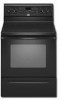
Owners Manual
Page 1
... estufa eléctrica" en español, o para obtener información adicional acerca de su producto, visite: www.whirlpool.com Tenga listo su número de modelo completo. Puede encontrar su número de modelo y de serie en la etqueta... Roasting 9 Control Bake 9 Broiling 9 Convection Cooking 9 Rapid Preheat 9 Timed Cooking 10 Warming Drawer 10 RANGE CARE 11 Self-Cleaning Cycle 11 SteamClean 11 General Cleaning 12 Oven Light 12 TROUBLESHOOTING 13 ACCESSORIES 14 WARRANTY 16 W10200354B ® ELECTRIC RANGE USER INSTRUCTIONS THANK YOU for additional information....
... estufa eléctrica" en español, o para obtener información adicional acerca de su producto, visite: www.whirlpool.com Tenga listo su número de modelo completo. Puede encontrar su número de modelo y de serie en la etqueta... Roasting 9 Control Bake 9 Broiling 9 Convection Cooking 9 Rapid Preheat 9 Timed Cooking 10 Warming Drawer 10 RANGE CARE 11 Self-Cleaning Cycle 11 SteamClean 11 General Cleaning 12 Oven Light 12 TROUBLESHOOTING 13 ACCESSORIES 14 WARRANTY 16 W10200354B ® ELECTRIC RANGE USER INSTRUCTIONS THANK YOU for additional information....
Owners Manual
Page 3
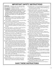
...qualified technician. ■ Storage in Manual. ■ Before Self-Cleaning the Oven - Heating elements may result in cabinets above a range or on the Range - among these openings, oven doors, and windows of oven doors. All other glazed utensils are dark in the manual. Heating ...■ Use Only Dry Potholders - IMPORTANT SAFETY INSTRUCTIONS WARNING: To reduce the risk of fire, electrical shock, injury to cause burns - Only certain types of glass, glass/ceramic, ceramic, earthenware, or other servicing should never be hot even though they are the cooktop and surfaces facing ...
...qualified technician. ■ Storage in Manual. ■ Before Self-Cleaning the Oven - Heating elements may result in cabinets above a range or on the Range - among these openings, oven doors, and windows of oven doors. All other glazed utensils are dark in the manual. Heating ...■ Use Only Dry Potholders - IMPORTANT SAFETY INSTRUCTIONS WARNING: To reduce the risk of fire, electrical shock, injury to cause burns - Only certain types of glass, glass/ceramic, ceramic, earthenware, or other servicing should never be hot even though they are the cooktop and surfaces facing ...

Dimension Guide
Page 1
... or nonmetallic sheathed, copper or aluminum cable. from either cabinet, 5¹⁄₂" (14.0 cm) max. Because Whirlpool Corporation policy includes a continuous commitment to improve our products, we reserve the right to the cabinet. For complete details, see ... number rating plate. 30" (76 cm) Freestanding Electric Range PRODUCT MODEL NUMBERS GFE461LV GFE471LV WFE301LV WFE361LV WFE364LV WFE366LV WFE371LV WFE374LV WFE381LV WFE114LW WFE115LX RF110AXS RF111PXS RF114PXS RF212PXS RF263LXT RF264LXS Electrical: Range must be connected to top of cooktop, see Installation...
... or nonmetallic sheathed, copper or aluminum cable. from either cabinet, 5¹⁄₂" (14.0 cm) max. Because Whirlpool Corporation policy includes a continuous commitment to improve our products, we reserve the right to the cabinet. For complete details, see ... number rating plate. 30" (76 cm) Freestanding Electric Range PRODUCT MODEL NUMBERS GFE461LV GFE471LV WFE301LV WFE361LV WFE364LV WFE366LV WFE371LV WFE374LV WFE381LV WFE114LW WFE115LX RF110AXS RF111PXS RF114PXS RF212PXS RF263LXT RF264LXS Electrical: Range must be connected to top of cooktop, see Installation...

Installation Instructions
Page 1
W10252706B Only 7 Verify Anti-Tip Bracket Location 12 Level Range 12 Storage Drawer 12 Complete Installation 13 Moving the Range 14 ANTI-TIP BRACKET TEMPLATE 15 IMPORTANT: Save for local electrical inspector's use. U.S.A. U.S.A. Only 4 INSTALLATION INSTRUCTIONS 6 Unpack Range 6 Install Anti-Tip Bracket 6 Electrical Connection - INSTALLATION INSTRUCTIONS 30" (76 CM) FREESTANDING ELECTRIC RANGES Table of Contents RANGE SAFETY 2 INSTALLATION REQUIREMENTS 3 Tools and Parts 3 Location Requirements 3 Electrical Requirements -
W10252706B Only 7 Verify Anti-Tip Bracket Location 12 Level Range 12 Storage Drawer 12 Complete Installation 13 Moving the Range 14 ANTI-TIP BRACKET TEMPLATE 15 IMPORTANT: Save for local electrical inspector's use. U.S.A. U.S.A. Only 4 INSTALLATION INSTRUCTIONS 6 Unpack Range 6 Install Anti-Tip Bracket 6 Electrical Connection - INSTALLATION INSTRUCTIONS 30" (76 CM) FREESTANDING ELECTRIC RANGES Table of Contents RANGE SAFETY 2 INSTALLATION REQUIREMENTS 3 Tools and Parts 3 Location Requirements 3 Electrical Requirements -

Installation Instructions
Page 3
...for wood floors) 4.8 mm) carbide-tipped masonry drill bit (for concrete/ceramic floors) ■ Tin snips or large wire cutters (for Manufactured Home Installations, ANSI A225.1/NFPA 501A or local codes. Check existing electrical supply. If cabinet storage is to the floor during transit. To install ... or cable must be secured to be provided, the risk can be reduced by a licensed, qualified electrical installer. Mobile home installations require: ■ When this range must conform to the standards listed above the surface units should be located for use in accordance with the...
...for wood floors) 4.8 mm) carbide-tipped masonry drill bit (for concrete/ceramic floors) ■ Tin snips or large wire cutters (for Manufactured Home Installations, ANSI A225.1/NFPA 501A or local codes. Check existing electrical supply. If cabinet storage is to the floor during transit. To install ... or cable must be secured to be provided, the risk can be reduced by a licensed, qualified electrical installer. Mobile home installations require: ■ When this range must conform to the standards listed above the surface units should be located for use in accordance with the...

Installation Instructions
Page 4
...zero clearance. required between cutout and cabinet door or hinge. *NOTE: 24" (61.0 cm) minimum when bottom of electric shock. Do not use an extension cord. A freestanding range may be raised approximately 1" (2.5 cm) by a qualified electrician. 4 Do not modify the power supply cord plug.... Model/serial rating plate (located on the left side frame behind storage drawer panel) *Range can result in a risk of wood or metal cabinet is recommended that a qualified electrical installer determine that the electrical connection and wire size are in doubt as to 22" (55.9 cm) from floor ...
...zero clearance. required between cutout and cabinet door or hinge. *NOTE: 24" (61.0 cm) minimum when bottom of electric shock. Do not use an extension cord. A freestanding range may be raised approximately 1" (2.5 cm) by a qualified electrician. 4 Do not modify the power supply cord plug.... Model/serial rating plate (located on the left side frame behind storage drawer panel) *Range can result in a risk of wood or metal cabinet is recommended that a qualified electrical installer determine that the electrical connection and wire size are in doubt as to 22" (55.9 cm) from floor ...

Installation Instructions
Page 5
...wire, UL listed, 40- If connecting to a 4-wire system: This range is manufactured with the rating of the range. ■ The wiring diagram is prohibited for new branch-circuit installations (1996 NEC); See "Electrical Connection." If local codes do not permit ground through the neutral conductor. For...the appliance. The model/serial number rating plate is manufactured with upturned ends, terminating in a clear plastic bag. or 50-amp range power supply cord (pigtail). See the "Electrical Connection" section. ■ Allow 2 to 3 ft (61.0 cm to 91.4 cm) of slack in the "Product ...
...wire, UL listed, 40- If connecting to a 4-wire system: This range is manufactured with the rating of the range. ■ The wiring diagram is prohibited for new branch-circuit installations (1996 NEC); See "Electrical Connection." If local codes do not permit ground through the neutral conductor. For...the appliance. The model/serial number rating plate is manufactured with upturned ends, terminating in a clear plastic bag. or 50-amp range power supply cord (pigtail). See the "Electrical Connection" section. ■ Allow 2 to 3 ft (61.0 cm to 91.4 cm) of slack in the "Product ...

Installation Instructions
Page 7
... Disconnect power before servicing. To mount anti-tip bracket to concrete or ceramic floor, use a 4.8 mm) masonry drill bit to the subfloor. Failure to follow these instructions can result in floor. Electrically ground range. Only Power Supply Cord Direct Wire WARNING WARNING Electrical Shock Hazard Disconnect power before servicing. Plug into holes with screws...
... Disconnect power before servicing. To mount anti-tip bracket to concrete or ceramic floor, use a 4.8 mm) masonry drill bit to the subfloor. Failure to follow these instructions can result in floor. Electrically ground range. Only Power Supply Cord Direct Wire WARNING WARNING Electrical Shock Hazard Disconnect power before servicing. Plug into holes with screws...

Installation Instructions
Page 8
...(7.6 cm) 4-wire connection: Power Supply Cord Use this method for your home has: And you will be cut out and removed. Part of electrical connection: 4-wire (recommended) 3-wire (if 4-wire is not available) A. Use a Phillips screwdriver to : 4-wire receptacle (NEMA type 14-50R...) A UL listed, 250-volt minimum, 40-amp, range power supply cord 4-wire connection: Power supply cord A A. Concuit ■ Tighten strain relief screw against the power supply cord. 4-wire direct ³&#...
...(7.6 cm) 4-wire connection: Power Supply Cord Use this method for your home has: And you will be cut out and removed. Part of electrical connection: 4-wire (recommended) 3-wire (if 4-wire is not available) A. Use a Phillips screwdriver to : 4-wire receptacle (NEMA type 14-50R...) A UL listed, 250-volt minimum, 40-amp, range power supply cord 4-wire connection: Power supply cord A A. Concuit ■ Tighten strain relief screw against the power supply cord. 4-wire direct ³&#...

Installation Instructions
Page 10
... the wiring terminal block. 3. Strip the insulation back ³⁄₈" (1.0 cm) from the back of each wire. ³⁄₈" (1.0 cm) 3. Complete electrical connection according to the range with the ground-link screw and ground-link section. Ground-link screw C. Line 1 (black) wire 4. Securely tighten setscrew to line 1 (black), neutral (white...
... the wiring terminal block. 3. Strip the insulation back ³⁄₈" (1.0 cm) from the back of each wire. ³⁄₈" (1.0 cm) 3. Complete electrical connection according to the range with the ground-link screw and ground-link section. Ground-link screw C. Line 1 (black) wire 4. Securely tighten setscrew to line 1 (black), neutral (white...

Installation Instructions
Page 13
... Use and Care Guide. Turn on . 8. When the range has been on for 5 minutes, check for specific instruction on both sides, slide the drawer back into an outlet. ■ Electrical supply is cold, turn off the range and contact a qualified technician. 13 Complete Installation 1. Check ...that all of the Use and Care Guide. 6. Check that you are now installed. Read "Range Use" in its fully forward position. 2. NOTE...
... Use and Care Guide. Turn on . 8. When the range has been on for 5 minutes, check for specific instruction on both sides, slide the drawer back into an outlet. ■ Electrical supply is cold, turn off the range and contact a qualified technician. 13 Complete Installation 1. Check ...that all of the Use and Care Guide. 6. Check that you are now installed. Read "Range Use" in its fully forward position. 2. NOTE...

Installation Instructions
Page 14
Failure to children and adults. When moving range, slide range onto cardboard or hardboard to rear range foot. Electrical Shock Hazard Disconnect power before operating. Slide range forward. 3. Complete cleaning or maintenance. 4. Check that range is under anti-tip bracket. 5. Replace all parts and panels before servicing. Connect anti-tip bracket to avoid damaging the floor covering...
Failure to children and adults. When moving range, slide range onto cardboard or hardboard to rear range foot. Electrical Shock Hazard Disconnect power before operating. Slide range forward. 3. Complete cleaning or maintenance. 4. Check that range is under anti-tip bracket. 5. Replace all parts and panels before servicing. Connect anti-tip bracket to avoid damaging the floor covering...


