
User Manual
Page 2
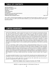
...how long an implied warranty lasts. TABLE OF CONTENTS LIMITED WARRANTY 2 IMPORTANT PRECAUTIONS 3 BEFORE YOU BEGIN 4 ASSEMBLY 5 CABLE DIAGRAMS 19 ADJUSTMENT 21 TROUBLE-SHOOTING AND MAINTENANCE 22 WEIGHT RESISTANCE CHART 23 ORDERING REPLACEMENT PARTS Back Cover Note:... set forth herein. Remove the PART LIST/EXPLODED DRAWING and the PART IDENTIFICATION CHART before beginning assembly. This warranty does not extend to any implied warranties of merchantability or fitness for a period ... 900 de l'Industrie, St-Jérôme, QC J7Y 4B8 WEIDER is in its authorized service centers.
...how long an implied warranty lasts. TABLE OF CONTENTS LIMITED WARRANTY 2 IMPORTANT PRECAUTIONS 3 BEFORE YOU BEGIN 4 ASSEMBLY 5 CABLE DIAGRAMS 19 ADJUSTMENT 21 TROUBLE-SHOOTING AND MAINTENANCE 22 WEIGHT RESISTANCE CHART 23 ORDERING REPLACEMENT PARTS Back Cover Note:... set forth herein. Remove the PART LIST/EXPLODED DRAWING and the PART IDENTIFICATION CHART before beginning assembly. This warranty does not extend to any implied warranties of merchantability or fitness for a period ... 900 de l'Industrie, St-Jérôme, QC J7Y 4B8 WEIDER is in its authorized service centers.
User Manual
Page 5
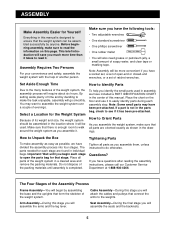
... evenings. If you have been pre-attached. You may have questions after reading the assembly instructions, please call our Customer Service Department at 1-888-936-4266. Cable Assembly-During this stage you will require about six hours. ASSEMBLY Make Assembly Easier for Yourself Everything in this manual is designed to ensure that there is enough...
... evenings. If you have been pre-attached. You may have questions after reading the assembly instructions, please call our Customer Service Department at 1-888-936-4266. Cable Assembly-During this stage you will require about six hours. ASSEMBLY Make Assembly Easier for Yourself Everything in this manual is designed to ensure that there is enough...
User Manual
Page 10
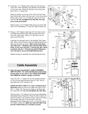
... a Pulley in the two Adjustable Pulley Plates with a 3/8" Jam Nut (18). Attach a 3/8" x 2 1/2" Eyebolt (83) to assemble the Left Butterfly Arm (67). 37 67 Cable Assembly 37 64 65 25 14. Have a second person slide the Right Butterfly Arm (68) onto the axle, as shown. 5 39 4...a 3/8" x 2" Bolt (35) and a 3/8" Nylon Locknut (4). Refer to the CABLE DIAGRAMS and CABLE ID CHART on the Left and Right Butterfly Arms (67, 68). Open the parts bag labelled "CABLE ASSEMBLY AND PULLEYS." For cable identification and routing during steps 14-32, refer to the inset draw- Secure 15 15...
... a Pulley in the two Adjustable Pulley Plates with a 3/8" Jam Nut (18). Attach a 3/8" x 2 1/2" Eyebolt (83) to assemble the Left Butterfly Arm (67). 37 67 Cable Assembly 37 64 65 25 14. Have a second person slide the Right Butterfly Arm (68) onto the axle, as shown. 5 39 4...a 3/8" x 2" Bolt (35) and a 3/8" Nylon Locknut (4). Refer to the CABLE DIAGRAMS and CABLE ID CHART on the Left and Right Butterfly Arms (67, 68). Open the parts bag labelled "CABLE ASSEMBLY AND PULLEYS." For cable identification and routing during steps 14-32, refer to the inset draw- Secure 15 15...
User Manual
Page 25
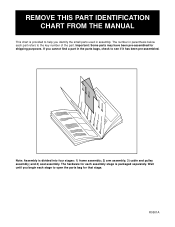
... THIS PART IDENTIFICATION CHART FROM THE MANUAL This chart is packaged separately. The hardware for shipping purposes. Note: Assembly is divided into four stages: 1) frame assembly; 2) arm assembly; 3) cable and pulley assembly; Important: Some parts may have been pre-assembled for each part refers to help you identify the small parts used in parenthesis below each...
... THIS PART IDENTIFICATION CHART FROM THE MANUAL This chart is packaged separately. The hardware for shipping purposes. Note: Assembly is divided into four stages: 1) frame assembly; 2) arm assembly; 3) cable and pulley assembly; Important: Some parts may have been pre-assembled for each part refers to help you identify the small parts used in parenthesis below each...


