

English Manual
Page 2
... Important Precautions 2 Before You Begin 3 Assembly 4 How to Use the Home Gym System 23 Trouble-shooting and Maintenance 25 Cable Diagrams 26 Weight Resistance Chart 27 Ordering Replacement Parts Back Cover Limited Warranty Back Cover Note: A PART LIST/EXPLODED DRAWING and a PART IDENTIFICATION CHART are attached... are raised. Read all instructions in this product. 2 Inspect and tighten all of this manual and in use the VKR station when either weight stack is fully inserted and folded down . 11. When using the home gym system. 1. Do not use . If you are exercising,...
... Important Precautions 2 Before You Begin 3 Assembly 4 How to Use the Home Gym System 23 Trouble-shooting and Maintenance 25 Cable Diagrams 26 Weight Resistance Chart 27 Ordering Replacement Parts Back Cover Limited Warranty Back Cover Note: A PART LIST/EXPLODED DRAWING and a PART IDENTIFICATION CHART are attached... are raised. Read all instructions in this product. 2 Inspect and tighten all of this manual and in use the VKR station when either weight stack is fully inserted and folded down . 11. When using the home gym system. 1. Do not use . If you are exercising,...
English Manual
Page 3
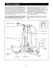
...Mountain Time (excluding holidays). Width: 64 in . The WEIDER PRO¨ 9835 offers a selection of weight stations designed to achieve the specific results you , please note the product model number and serial number before using the WEIDER PRO¨ 9835 Home Gym System. Whether your goal is WESY41080. Customer ... until 6 p.m. Backrests Butterfly Arms VKR Station Press Arm Leg Lever Low Pulley Station Foot Plate Weight Stacks 3 Leg Press Plate The model number is to the WEIDER PRO¨ 9835 (see the front cover of the body. The serial number can be found on a decal...
...Mountain Time (excluding holidays). Width: 64 in . The WEIDER PRO¨ 9835 offers a selection of weight stations designed to achieve the specific results you , please note the product model number and serial number before using the WEIDER PRO¨ 9835 Home Gym System. Whether your goal is WESY41080. Customer ... until 6 p.m. Backrests Butterfly Arms VKR Station Press Arm Leg Lever Low Pulley Station Foot Plate Weight Stacks 3 Leg Press Plate The model number is to the WEIDER PRO¨ 9835 (see the front cover of the body. The serial number can be found on a decal...

English Manual
Page 4
... the base and the upright frames that assembly stage. Do not dispose of ratchet wrenches. You may have broken it is a sophisticated product with the weights. Giving Yourself a Good Start Before you are found in individual packages in the parts bag, check to make sure all moving arms with each stage...
... the base and the upright frames that assembly stage. Do not dispose of ratchet wrenches. You may have broken it is a sophisticated product with the weights. Giving Yourself a Good Start Before you are found in individual packages in the parts bag, check to make sure all moving arms with each stage...

English Manual
Page 5
... Bolts. Hand tighten two 5/16Ó Nylon Locknuts (40) onto the 1 Carriage Bolts. Insert four 5/16Ó x 2 1/2Ó Carriage Bolts (49) up through the Weight Base (14) and place it on the floor. Hand tighten two 5/16Ó Nylon Locknuts (40) onto the Carriage Bolts. Before beginning assembly, make sure... Do not tighten the Nylon Locknuts yet. 1 14 56 55 20 49 58 20 49 13 40 49 2. Attach the Press Base (13) to the Weight Base. Locate and open the parts bags labeled ÒFRAME ASSEMBLY BAG ONEÓ and ÒFRAME ASSEMBLY BAG TWO.Ó Press a 2Ó Square ...
... Bolts. Hand tighten two 5/16Ó Nylon Locknuts (40) onto the 1 Carriage Bolts. Insert four 5/16Ó x 2 1/2Ó Carriage Bolts (49) up through the Weight Base (14) and place it on the floor. Hand tighten two 5/16Ó Nylon Locknuts (40) onto the Carriage Bolts. Before beginning assembly, make sure... Do not tighten the Nylon Locknuts yet. 1 14 56 55 20 49 58 20 49 13 40 49 2. Attach the Press Base (13) to the Weight Base. Locate and open the parts bags labeled ÒFRAME ASSEMBLY BAG ONEÓ and ÒFRAME ASSEMBLY BAG TWO.Ó Press a 2Ó Square ...

English Manual
Page 7
Press a Weight Tube Bumper (26) into each Weight 6 Tube (25). Insert a Weight Tube (25) into each stack of Weights (90). Make sure the pins on the Weight Tubes are on the Weight Base (14). 5 Slide a Weight Bumper (27) onto each of the Weight Guides (23). 90 Slide eight Weights (90) onto each stack of Weight Guides (23). Insert two Weight Guides (23) into each of the brackets on the indicated side of each set of Weights. 90 Pin Grooves 27 23 23 14 Pin Grooves 27 6. Make sure the pin grooves are in the pin grooves in the upper Weights. 25 26 90 90 7 5.
Press a Weight Tube Bumper (26) into each Weight 6 Tube (25). Insert a Weight Tube (25) into each stack of Weights (90). Make sure the pins on the Weight Tubes are on the Weight Base (14). 5 Slide a Weight Bumper (27) onto each of the Weight Guides (23). 90 Slide eight Weights (90) onto each stack of Weight Guides (23). Insert two Weight Guides (23) into each of the brackets on the indicated side of each set of Weights. 90 Pin Grooves 27 23 23 14 Pin Grooves 27 6. Make sure the pin grooves are in the pin grooves in the upper Weights. 25 26 90 90 7 5.

English Manual
Page 8
Attach the upper ends of one set of Weight Guides (23) to the Lat Upright (1) with a 5/16Ó x 6Ó Bolt (67), two 1/2Ó x ...5/16Ó Washers (20) and two 5/16Ó Nylon Locknuts (40). Attach the upper ends of the other set of Weight Guides (23) in the same manner. Lubricate the insides of the VKR Upright. 8 2 55 20 55 56 98 55 40 ...not tighten the Nylon Locknuts yet. Do not tighten the Nylon Locknuts yet. Slide a Top Weight onto each set of Weight Guides (23). 24 Lubricate 23 24 Lubricate 23 8. Before continuing, firmly tighten all nylon locknuts used in...
Attach the upper ends of one set of Weight Guides (23) to the Lat Upright (1) with a 5/16Ó x 6Ó Bolt (67), two 1/2Ó x ...5/16Ó Washers (20) and two 5/16Ó Nylon Locknuts (40). Attach the upper ends of the other set of Weight Guides (23) in the same manner. Lubricate the insides of the VKR Upright. 8 2 55 20 55 56 98 55 40 ...not tighten the Nylon Locknuts yet. Do not tighten the Nylon Locknuts yet. Slide a Top Weight onto each set of Weight Guides (23). 24 Lubricate 23 24 Lubricate 23 8. Before continuing, firmly tighten all nylon locknuts used in...

English Manual
Page 13
...the Cable Trap is the shortest 23 Cable. Wrap the Rear Cable (87) around a 3 1/2Ó Pulley (82). Place a 1/2Ó Washer (68) and a 1 1/4Ó x 26 1/2Ó Weight Spacer (10) on top of the Pulley and that the Cable and Pulley move smoothly. 80 82 42 50 84 87 82 84 25. Note...Cable (87) into the upper end of the Rear Cable (87). Thread a 1/2Ó Plain Nut (35) onto the end of the Weight Tube (25) until the Weight Spacer (10) touches the Weight Tube. See the inset drawing. Thread another 5/16Ó Nylon Jam Nut (91) onto the Bolt, but do not fully tighten...
...the Cable Trap is the shortest 23 Cable. Wrap the Rear Cable (87) around a 3 1/2Ó Pulley (82). Place a 1/2Ó Washer (68) and a 1 1/4Ó x 26 1/2Ó Weight Spacer (10) on top of the Pulley and that the Cable and Pulley move smoothly. 80 82 42 50 84 87 82 84 25. Note...Cable (87) into the upper end of the Rear Cable (87). Thread a 1/2Ó Plain Nut (35) onto the end of the Weight Tube (25) until the Weight Spacer (10) touches the Weight Tube. See the inset drawing. Thread another 5/16Ó Nylon Jam Nut (91) onto the Bolt, but do not fully tighten...

English Manual
Page 18
... closed loop on the Lat Upright (1) with a 3/8Ó x 2Ó 43 Bolt (50) and a 3/8Ó Nylon Locknut (42). Place a 1/2Ó Washer (68) and a 1 1/4Ó x 44 1/2Ó Weight Spacer (10) on top of the High Cable (85). Attach the closed loop at the end of the Low Cable 45 (86) to the Top... the Cable Trap is turned towards the bracket. 1 95 86 40 18 The Cable 42 must be downward. Note: It is necessary to lift the Weight Tube (25) with two holes should be routed from the direction shown. 2 50 82 85 44. Thread the end of the Rear Cable (87) into...
... closed loop on the Lat Upright (1) with a 3/8Ó x 2Ó 43 Bolt (50) and a 3/8Ó Nylon Locknut (42). Place a 1/2Ó Washer (68) and a 1 1/4Ó x 44 1/2Ó Weight Spacer (10) on top of the High Cable (85). Attach the closed loop at the end of the Low Cable 45 (86) to the Top... the Cable Trap is turned towards the bracket. 1 95 86 40 18 The Cable 42 must be downward. Note: It is necessary to lift the Weight Tube (25) with two holes should be routed from the direction shown. 2 50 82 85 44. Thread the end of the Rear Cable (87) into...

English Manual
Page 22
... problem. Slide the Lock Pin (73) through the welded tubes on page 23 of the holes in the cables, you will be damaged when heavy weight is oriented correctly. Note that all parts have been properly tightened. IMPORTANT: If the cables are not properly installed, they may be explained in HOW...
... problem. Slide the Lock Pin (73) through the welded tubes on page 23 of the holes in the cables, you will be damaged when heavy weight is oriented correctly. Note that all parts have been properly tightened. IMPORTANT: If the cables are not properly installed, they may be explained in HOW...

English Manual
Page 23
... find the approximate amount of the home gym system can be reduced. How to Use the Home Gym System The instructions below describe how each weight station. 90 93 ATTACHING THE LAT BAR OR HANDLE TO THE HIGH PULLEY STATION Attach the Lat Bar (36) to the High Cable (85) with... High Cable so the Lat Bar is in the correct starting position for the exer- Adjust the length of either weight stack, insert a Weight Pin (93) under the desired Weight (90). The weight setting of the Chain between the Lat Bar and the Low Cable so the Lat Bar is in the correct starting...
... find the approximate amount of the home gym system can be reduced. How to Use the Home Gym System The instructions below describe how each weight station. 90 93 ATTACHING THE LAT BAR OR HANDLE TO THE HIGH PULLEY STATION Attach the Lat Bar (36) to the High Cable (85) with... High Cable so the Lat Bar is in the correct starting position for the exer- Adjust the length of either weight stack, insert a Weight Pin (93) under the desired Weight (90). The weight setting of the Chain between the Lat Bar and the Low Cable so the Lat Bar is in the correct starting...

English Manual
Page 25
... Pulley without the Cable Trap. If any slack is felt, the cables should be replaced, see ORDERING REPLACEMENT PARTS on the back cover of the weight stack. Loosen the 1/2Ó Plain Nut (35) on the home gym system, can be lifted off the pulleys often, it may have become twisted. If... is felt when using the other hole in the Pulley Plates 3 without the Cable Trap. If you use the home gym system. tightened, the top weight will need to be tightened in several ways: ¥ See drawing 1. Replace any slack is first used on the end of cable used . The home...
... Pulley without the Cable Trap. If any slack is felt, the cables should be replaced, see ORDERING REPLACEMENT PARTS on the back cover of the weight stack. Loosen the 1/2Ó Plain Nut (35) on the home gym system, can be lifted off the pulleys often, it may have become twisted. If... is felt when using the other hole in the Pulley Plates 3 without the Cable Trap. If you use the home gym system. tightened, the top weight will need to be tightened in several ways: ¥ See drawing 1. Replace any slack is first used on the end of cable used . The home...

English Manual
Page 27
..., as well as friction between the cables, pulleys, and weight guides. The other numbers refer to the 12.5 lbs. WEIGHT PLATES Top 1 2 3 4 5 6 7 8 PRESS ARM (lbs.) 27 53 79 101 125 148 175 205 240 BUTTERFLY ARM (lbs.) LEG LEVER (lbs.) 20 9 37 18 50 33 ... PRESS (lbs.) 52 94 141 180 228 263 310 358 410 27 High Cable (85) 4 2 High PulleyÑ1 3 1ÑTop Frame Rear Cable (87) 3 2 4ÑWeight Stack Weight StackÑ5 Weight Resistance Chart This chart shows the approximate weight resistance at each station. ÒTopÓ refers to the 6.5 lbs.
..., as well as friction between the cables, pulleys, and weight guides. The other numbers refer to the 12.5 lbs. WEIGHT PLATES Top 1 2 3 4 5 6 7 8 PRESS ARM (lbs.) 27 53 79 101 125 148 175 205 240 BUTTERFLY ARM (lbs.) LEG LEVER (lbs.) 20 9 37 18 50 33 ... PRESS (lbs.) 52 94 141 180 228 263 310 358 410 27 High Cable (85) 4 2 High PulleyÑ1 3 1ÑTop Frame Rear Cable (87) 3 2 4ÑWeight Stack Weight StackÑ5 Weight Resistance Chart This chart shows the approximate weight resistance at each station. ÒTopÓ refers to the 6.5 lbs.

English Manual
Page 29
...1 Large Backrest 20 12 5/16Ó Washer 21 6 5Ó Plastic Grip 22 2 10Ó Pad 23 4 Weight Guide 24 2 Top Weight 25 2 Weight Tube 26 2 Weight Tube Bumper 27 4 Weight Bumper 28 2 Pad Tube 29 4 Foam Pad 30 1 Seat Knob 31 4 Pulley Plate 32 1 Right VKR Arm ...Bracket 85 1 High Cable 86 1 Low Cable 87 1 Rear Cable 88 1 Press Cable 89 1 Butterfly Cable 90 16 Weight 91 8 5/16Ó Nylon Jam Nut 92 3 5/16Ó x 3Ó Bolt 93 2 Weight Pin 94 3 3/8Ó x 3Ó Bolt 95 3 5/16Ó x 1Ó Bolt 96 1 Handle 97 1 ...
...1 Large Backrest 20 12 5/16Ó Washer 21 6 5Ó Plastic Grip 22 2 10Ó Pad 23 4 Weight Guide 24 2 Top Weight 25 2 Weight Tube 26 2 Weight Tube Bumper 27 4 Weight Bumper 28 2 Pad Tube 29 4 Foam Pad 30 1 Seat Knob 31 4 Pulley Plate 32 1 Right VKR Arm ...Bracket 85 1 High Cable 86 1 Low Cable 87 1 Rear Cable 88 1 Press Cable 89 1 Butterfly Cable 90 16 Weight 91 8 5/16Ó Nylon Jam Nut 92 3 5/16Ó x 3Ó Bolt 93 2 Weight Pin 94 3 3/8Ó x 3Ó Bolt 95 3 5/16Ó x 1Ó Bolt 96 1 Handle 97 1 ...


