
English Manual
Page 2
TABLE OF CONTENTS FULL 90 DAY WARRANTY 2 IMPORTANT PRECAUTIONS 3 BEFORE YOU BEGIN 4 ASSEMBLY 5 HOW TO USE THE HOME GYM SYSTEM 26 WEIGHT RESISTANCE CHART 28 TROUBLE-SHOOTING AND MAINTENANCE 29 CABLE DIAGRAMS 30 ORDERING REPLACEMENT PARTS Back Cover Note: A PART IDENTIFICATION CHART and a PART LIST/EXPLODED DRAWING ...are attached to the center of charge. FULL 90 DAY WARRANTY For 90 days from state to defect in material or workmanship in this SEARS WEIGHT SYSTEM EXERCISER, contact the nearest SEARS Service Center throughout the United States and SEARS will repair or replace the...
TABLE OF CONTENTS FULL 90 DAY WARRANTY 2 IMPORTANT PRECAUTIONS 3 BEFORE YOU BEGIN 4 ASSEMBLY 5 HOW TO USE THE HOME GYM SYSTEM 26 WEIGHT RESISTANCE CHART 28 TROUBLE-SHOOTING AND MAINTENANCE 29 CABLE DIAGRAMS 30 ORDERING REPLACEMENT PARTS Back Cover Note: A PART IDENTIFICATION CHART and a PART LIST/EXPLODED DRAWING ...are attached to the center of charge. FULL 90 DAY WARRANTY For 90 days from state to defect in material or workmanship in this SEARS WEIGHT SYSTEM EXERCISER, contact the nearest SEARS Service Center throughout the United States and SEARS will repair or replace the...
English Manual
Page 3
... precautions. 2. Replace any time while exercising, stop immediately and make sure that the cables are adequately informed of all parts often. The weights will fall with pre-existing health problems. Read all instructions in this or any commercial, rental or institutional setting. When using the leg .... Never release the press arm, butterfly arms, leg lever, leg press plate, lat bar, row bar, ab strap, or nylon strap while weights are exercising, stop immediately and begin cooling down. 16. Use the home gym system only on the pulleys at all of the pulleys. 6....
... precautions. 2. Replace any time while exercising, stop immediately and make sure that the cables are adequately informed of all parts often. The weights will fall with pre-existing health problems. Read all instructions in this or any commercial, rental or institutional setting. When using the leg .... Never release the press arm, butterfly arms, leg lever, leg press plate, lat bar, row bar, ab strap, or nylon strap while weights are exercising, stop immediately and begin cooling down. 16. Use the home gym system only on the pulleys at all of the pulleys. 6....
English Manual
Page 4
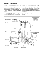
...with the parts that are labeled. Width: 70 in . The PRO 9735 offers a selection of weight stations designed to achieve the specific results you , please note the product model number and serial number before using the WEIDER® PRO 9735 Home Gym System. The serial number can be found on a... in. free HELPLINE at 1-800-736-6879, Monday through Saturday, 7 a.m. If you for selecting the versatile WEIDER® PRO 9735 Home Gym System. For your cardiovascular system, the PRO 9735 will help us assist you want. BEFORE YOU BEGIN Thank you have additional questions, please call our toll- The...
...with the parts that are labeled. Width: 70 in . The PRO 9735 offers a selection of weight stations designed to achieve the specific results you , please note the product model number and serial number before using the WEIDER® PRO 9735 Home Gym System. The serial number can be found on a... in. free HELPLINE at 1-800-736-6879, Monday through Saturday, 7 a.m. If you for selecting the versatile WEIDER® PRO 9735 Home Gym System. For your cardiovascular system, the PRO 9735 will help us assist you want. BEFORE YOU BEGIN Thank you have additional questions, please call our toll- The...

English Manual
Page 5
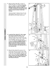
... assembly, 3) cable and pulley assembly and 4) seat and backrest assembly. FRAME ASSEMBLY 1. Press three 2" Square Outer Caps (58) onto the Weight Base (14) in a cleared area and remove the packing materials; The hardware for each stage is packaged separately. • Wait until you begin...have read the following tools: A socket set, a set of ratchet wrenches. Insert four 5/16" x 2 1/2" Carriage Bolts up through the Weight Base. do otherwise. Assembly will also be sure that you have been preattached for that assembly stage. • For help identifying the small parts...
... assembly, 3) cable and pulley assembly and 4) seat and backrest assembly. FRAME ASSEMBLY 1. Press three 2" Square Outer Caps (58) onto the Weight Base (14) in a cleared area and remove the packing materials; The hardware for each stage is packaged separately. • Wait until you begin...have read the following tools: A socket set, a set of ratchet wrenches. Insert four 5/16" x 2 1/2" Carriage Bolts up through the Weight Base. do otherwise. Assembly will also be sure that you have been preattached for that assembly stage. • For help identifying the small parts...

English Manual
Page 6
... a 2" Square Inner Cap (56) into each Carriage Bolt. Slide the Leg Press Upright (4) onto the indicated 5/16" x 2 1/2" Carriage Bolts (49) in the 3 Weight Base (14). Do not fully tighten the Nylon Locknuts. 13 14 49 49 4 40 16 20 55 1 14 40 49 6 Partially tighten a 5/16" Nylon Locknut... (40) onto each Carriage Bolt. Attach the other end of the Rear Seat Frame (16) to the Weight Base (14) with two 5/16" x 2.3/4" Bolts (55), two 5/16" Washers (20) and two 5/16" Nylon Locknuts (40). Slide the Ab Upright (1) ...
... a 2" Square Inner Cap (56) into each Carriage Bolt. Slide the Leg Press Upright (4) onto the indicated 5/16" x 2 1/2" Carriage Bolts (49) in the 3 Weight Base (14). Do not fully tighten the Nylon Locknuts. 13 14 49 49 4 40 16 20 55 1 14 40 49 6 Partially tighten a 5/16" Nylon Locknut... (40) onto each Carriage Bolt. Attach the other end of the Rear Seat Frame (16) to the Weight Base (14) with two 5/16" x 2.3/4" Bolts (55), two 5/16" Washers (20) and two 5/16" Nylon Locknuts (40). Slide the Ab Upright (1) ...

English Manual
Page 7
... 5/16" x 2 3/4" Bolts (55), two 5/16" Washers (20) and two 5/16" Nylon Locknuts (40). Do not fully tighten the Nylon Locknuts. Attach the other end of Weights. 5 55 20 40 8 4 56 40 13 49 6 23 23 67 40 14 69 7 90 Pin Grooves 90 Pin Grooves 27 27 23 23 7 Be sure... that the pin grooves are on the Weight Base (14). Slide the Front Seat Frame (8) onto the indicated 5/16" x 2 1/2" Carriage Bolts (49) in the same manner. 7. Do not overtighten the Nylon Locknut. Do...
... 5/16" x 2 3/4" Bolts (55), two 5/16" Washers (20) and two 5/16" Nylon Locknuts (40). Do not fully tighten the Nylon Locknuts. Attach the other end of Weights. 5 55 20 40 8 4 56 40 13 49 6 23 23 67 40 14 69 7 90 Pin Grooves 90 Pin Grooves 27 27 23 23 7 Be sure... that the pin grooves are on the Weight Base (14). Slide the Front Seat Frame (8) onto the indicated 5/16" x 2 1/2" Carriage Bolts (49) in the same manner. 7. Do not overtighten the Nylon Locknut. Do...

English Manual
Page 8
Insert a Weight Tube (25) into each 8 Weight Tube (25). Be sure that the pins on the Weight Tubes are in the pin grooves in the Top 9 Weights (24) as shown. Lubricate the insides of Weights (90). 8. Press a Weight Tube Bumper (26) into each set of Weight Guides (23). 24 Lubricate 23 23 Lubricate 24 8 Slide a Top Weight onto each stack of the holes in the upper Weights. 25 26 90 90 FRAME ASSEMBLY 9.
Insert a Weight Tube (25) into each 8 Weight Tube (25). Be sure that the pins on the Weight Tubes are in the pin grooves in the Top 9 Weights (24) as shown. Lubricate the insides of Weights (90). 8. Press a Weight Tube Bumper (26) into each set of Weight Guides (23). 24 Lubricate 23 23 Lubricate 24 8 Slide a Top Weight onto each stack of the holes in the upper Weights. 25 26 90 90 FRAME ASSEMBLY 9.

English Manual
Page 9
... (40). 11. Do not tighten the Nylon Locknuts yet. Do not tighten the Nylon Locknuts yet. 12. Attach the upper ends of one set of Weight Guides (23) in steps 2 through 12. 10 2 56 40 20 20 56 55 70 55 56 56 3 11 55 20 2 92 3 98 40 1 12 40... the Top Frame (2). Before continuing, firmly tighten all nylon locknuts used in the same manner. Press two 1" Round Inner Caps (70) into each end of Weight Guides (23) to the Top Frame (2) with a 5/16" x 6" Bolt (67), two 1/2" x 3/4" Spacers (69) and a 5/16" Nylon Locknut (40). Attach the Top Frame (2) to the Leg...
... (40). 11. Do not tighten the Nylon Locknuts yet. Do not tighten the Nylon Locknuts yet. 12. Attach the upper ends of one set of Weight Guides (23) in steps 2 through 12. 10 2 56 40 20 20 56 55 70 55 56 56 3 11 55 20 2 92 3 98 40 1 12 40... the Top Frame (2). Before continuing, firmly tighten all nylon locknuts used in the same manner. Press two 1" Round Inner Caps (70) into each end of Weight Guides (23) to the Top Frame (2) with a 5/16" x 6" Bolt (67), two 1/2" x 3/4" Spacers (69) and a 5/16" Nylon Locknut (40). Attach the Top Frame (2) to the Leg...
English Manual
Page 16
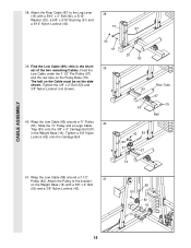
... in the inset drawing. Wrap the Rear Cable around a 3 1/2" Pulley (82). Do not overtighten the Nylon Locknut; Attach the High Cable (86) to the indicated Weight Tube (25) with a 1/4" Nylon Locknut (44) and a 1/4" Washer (37). Attach the Small "U" Bracket (32) to a Small "U" 33 Bracket (32) with a 5/16" x 1 3/4" Bolt (68) and a 5/16...
... in the inset drawing. Wrap the Rear Cable around a 3 1/2" Pulley (82). Do not overtighten the Nylon Locknut; Attach the High Cable (86) to the indicated Weight Tube (25) with a 1/4" Nylon Locknut (44) and a 1/4" Washer (37). Attach the Small "U" Bracket (32) to a Small "U" 33 Bracket (32) with a 5/16" x 1 3/4" Bolt (68) and a 5/16...
English Manual
Page 18
..." Bushing (61) and a 5/16" Nylon Locknut (40). 15 87 39. Slide the "V" Pulley and a Large Cable Trap (83) onto the 3/8" x 4" Carriage Bolt (57) in the Weight Base (14). Tighten a 3/8" Nylon Locknut (42) onto the Carriage Bolt. 40 61 39 20 92 89 50 40 42 89 83 81 57 Row Tube...). 89 50 82 42 14 18 CABLE ASSEMBLY 38. Tighten the 3/8" x 2" Bolt (50) and 3/8" Nylon Locknut (not shown). 40. Feed the Low Cable under the 3 1/2" Pro Pulley (97) and the row tube on the Pulley Base (79).
..." Bushing (61) and a 5/16" Nylon Locknut (40). 15 87 39. Slide the "V" Pulley and a Large Cable Trap (83) onto the 3/8" x 4" Carriage Bolt (57) in the Weight Base (14). Tighten a 3/8" Nylon Locknut (42) onto the Carriage Bolt. 40 61 39 20 92 89 50 40 42 89 83 81 57 Row Tube...). 89 50 82 42 14 18 CABLE ASSEMBLY 38. Tighten the 3/8" x 2" Bolt (50) and 3/8" Nylon Locknut (not shown). 40. Feed the Low Cable under the 3 1/2" Pro Pulley (97) and the row tube on the Pulley Base (79).

English Manual
Page 20
...). 46. It should be threaded onto the end of the Cable so only a couple of 46 the Press Cable (88) to the indi- 32 cated Weight Tube (25) with a 1/4" Nylon Locknut (44) and a 1/4" Washer (37). Note: The 3 1/2" Pulley (82) in place. Attach the Low Cable (89) to hold the Cable in...
...). 46. It should be threaded onto the end of the Cable so only a couple of 46 the Press Cable (88) to the indi- 32 cated Weight Tube (25) with a 1/4" Nylon Locknut (44) and a 1/4" Washer (37). Note: The 3 1/2" Pulley (82) in place. Attach the Low Cable (89) to hold the Cable in...

English Manual
Page 25
.... If there is used. IMPORTANT: If the cables are not properly installed, they may be explained in the cables, you will be damaged when heavy weight is any slack in HOW TO USE THE HOME GYM SYSTEM, beginning on page 26 of this manual. See the CABLE DIAGRAMS on page 29...
.... If there is used. IMPORTANT: If the cables are not properly installed, they may be explained in the cables, you will be damaged when heavy weight is any slack in HOW TO USE THE HOME GYM SYSTEM, beginning on page 26 of this manual. See the CABLE DIAGRAMS on page 29...
English Manual
Page 26
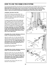
...93 To change the weight setting of either weight stack can be changed from the weight setting. CHANGING THE WEIGHT SETTING The PRO 9735 features two weight stacks. The other weight stack is touching the Weights and turn the bent end downward. Insert the Weight Pin until the bent end of the Weight Pin is con- ...correct starting position for 36 the exercise to the High Cable (86) with two Cable Clips. Adjust the length of resistance at each weight station. 90 93 ATTACHING THE LAT BAR, ROW BAR, OR NYLON STRAP TO THE HIGH PULLEY STATION Attach the Lat Bar (36)...
...93 To change the weight setting of either weight stack can be changed from the weight setting. CHANGING THE WEIGHT SETTING The PRO 9735 features two weight stacks. The other weight stack is touching the Weights and turn the bent end downward. Insert the Weight Pin until the bent end of the Weight Pin is con- ...correct starting position for 36 the exercise to the High Cable (86) with two Cable Clips. Adjust the length of resistance at each weight station. 90 93 ATTACHING THE LAT BAR, ROW BAR, OR NYLON STRAP TO THE HIGH PULLEY STATION Attach the Lat Bar (36)...

English Manual
Page 28
... CHART This chart shows the approximate weight resistance at each weight station may vary due to differences in individual weight plates, as well as friction between the cables, pulleys and weight guides. 28 top weight. WEIGHT PLATES Top 1 2 3 4 5 6 7 8 PRESS ARM (lbs.) BUTTERFLY ARM (lbs.) LEG LEVER (lbs.) 36 19 10 63 35 25 97 55 38... 126 480 135 The actual resistance at each butterfly arm. "Top" refers to the 12.5 lb. The butterfly arm resistance is the resistance for each weight station. The other numbers refer to the 6.5 lb.
... CHART This chart shows the approximate weight resistance at each weight station may vary due to differences in individual weight plates, as well as friction between the cables, pulleys and weight guides. 28 top weight. WEIGHT PLATES Top 1 2 3 4 5 6 7 8 PRESS ARM (lbs.) BUTTERFLY ARM (lbs.) LEG LEVER (lbs.) 36 19 10 63 35 25 97 55 38... 126 480 135 The actual resistance at each butterfly arm. "Top" refers to the 12.5 lb. The butterfly arm resistance is the resistance for each weight station. The other numbers refer to the 6.5 lb.
English Manual
Page 29
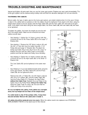
... (89) will be tightened in the proper 2 position and that connects the end of the weight stack. Keep the Cable Traps for future use solvents. The home gym system can be tightened....89 32 • See drawing 2. Remove the cable and re-install it is felt when using the weight stack closest to the ab upright, both the High Cable (86) and the Rear Cable (87)...Cable Trap (80), 3 1/2" Pulley (82) and Large "U" Bracket (84). If the cables are overtightened, the top weight will need to slip off the pulleys often, it may have become twisted. Do not overtighten the cables. When the ...
... (89) will be tightened in the proper 2 position and that connects the end of the weight stack. Keep the Cable Traps for future use solvents. The home gym system can be tightened....89 32 • See drawing 2. Remove the cable and re-install it is felt when using the weight stack closest to the ab upright, both the High Cable (86) and the Rear Cable (87)...Cable Trap (80), 3 1/2" Pulley (82) and Large "U" Bracket (84). If the cables are overtightened, the top weight will need to slip off the pulleys often, it may have become twisted. Do not overtighten the cables. When the ...
English Manual
Page 30
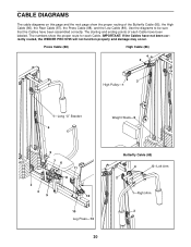
The numbers show the proper routing of each Cable. Press Cable (88) High Cable (86) 4 2 3 High Pulley-1 1-Long "U" Bracket 4 Weight Stack-5 5 76 11 8 2 3 9 12 10 Leg Press-13 30 Butterfly Cable (85) 4 5-Left Arm 2 1-Right Arm 3 IMPORTANT: If the Cables have been assembled correctly. CABLE ... (87), the Press Cable (88), and the Low Cable (89). Use the diagrams to be sure that the Cables have not been correctly routed, the WEIDER PRO 9735 will not function properly and damage may occur.
The numbers show the proper routing of each Cable. Press Cable (88) High Cable (86) 4 2 3 High Pulley-1 1-Long "U" Bracket 4 Weight Stack-5 5 76 11 8 2 3 9 12 10 Leg Press-13 30 Butterfly Cable (85) 4 5-Left Arm 2 1-Right Arm 3 IMPORTANT: If the Cables have been assembled correctly. CABLE ... (87), the Press Cable (88), and the Low Cable (89). Use the diagrams to be sure that the Cables have not been correctly routed, the WEIDER PRO 9735 will not function properly and damage may occur.

English Manual
Page 31
Low Cable (89) 6 4 5 Weight Stack-7 Rear Cable (87) 3 Ab Pulley-1 2 5-Leg Lever 3 4 1-Low Pulley 2 31
Low Cable (89) 6 4 5 Weight Stack-7 Rear Cable (87) 3 Ab Pulley-1 2 5-Leg Lever 3 4 1-Low Pulley 2 31
English Manual
Page 34
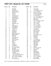
... Trap "V" Pulley 3 1/2" Pulley Large Cable Trap Large "U" Bracket Butterfly Cable High Cable Rear Cable Press Cable Low Cable Weight 5/16" Nylon Jam Nut 5/16" x 3" Bolt Weight Pin Row Bar Small Bumper Large Lock Pin 3 1/2" Pro Pulley Support Plate 1/4" x 5/8"" Screw #10 x 1" Tap Screw User's Manual Exercise Poster Note: "#" indicates a non-illustrated part. Qty. 1...Press Plate Press Frame Press Base Weight Base Leg Lever Rear Seat Frame Seat Small Backrest Large Backrest 5/16" Washer 5" Plastic Grip 10" Pad Weight Guide Top Weight Weight Tube Weight Tube Bumper Weight Bumper Pad Tube Foam Pad ...
... Trap "V" Pulley 3 1/2" Pulley Large Cable Trap Large "U" Bracket Butterfly Cable High Cable Rear Cable Press Cable Low Cable Weight 5/16" Nylon Jam Nut 5/16" x 3" Bolt Weight Pin Row Bar Small Bumper Large Lock Pin 3 1/2" Pro Pulley Support Plate 1/4" x 5/8"" Screw #10 x 1" Tap Screw User's Manual Exercise Poster Note: "#" indicates a non-illustrated part. Qty. 1...Press Plate Press Frame Press Base Weight Base Leg Lever Rear Seat Frame Seat Small Backrest Large Backrest 5/16" Washer 5" Plastic Grip 10" Pad Weight Guide Top Weight Weight Tube Weight Tube Bumper Weight Bumper Pad Tube Foam Pad ...


