
English Manual
Page 1
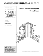
Sears, Roebuck and Co., Hoffman Estates, IL 60179 Save this equipment. WEIGHT SYSTEM EXERCISER User's Manual Serial Number Decal (under seat) • Assembly • Adjustments • Troubleshooting • Part List and Drawing CAUTION Read all precautions and instructions in the space above for future reference. Model No. 831.14623.0 Serial No. Write the serial number in this manual before using this manual for future reference.
Sears, Roebuck and Co., Hoffman Estates, IL 60179 Save this equipment. WEIGHT SYSTEM EXERCISER User's Manual Serial Number Decal (under seat) • Assembly • Adjustments • Troubleshooting • Part List and Drawing CAUTION Read all precautions and instructions in the space above for future reference. Model No. 831.14623.0 Serial No. Write the serial number in this manual before using this manual for future reference.
English Manual
Page 2
TABLE OF CONTENTS IMPORTANT PRECAUTIONS 3 BEFORE YOU BEGIN 4 PART IDENTIFICATION CHART 5 ASSEMBLY 7 ADJUSTMENTS 28 WEIGHT RESISTANCE CHART 31 CABLE DIAGRAM 32 MAINTENANCE 34 EXERCISE GUIDELINES 35 PART LIST 39 EXPLODED DRAWING 41 ORDERING REPLACEMENT PARTS Back Cover 90 DAY FULL WARRANTY Back Cover 2
TABLE OF CONTENTS IMPORTANT PRECAUTIONS 3 BEFORE YOU BEGIN 4 PART IDENTIFICATION CHART 5 ASSEMBLY 7 ADJUSTMENTS 28 WEIGHT RESISTANCE CHART 31 CABLE DIAGRAM 32 MAINTENANCE 34 EXERCISE GUIDELINES 35 PART LIST 39 EXPLODED DRAWING 41 ORDERING REPLACEMENT PARTS Back Cover 90 DAY FULL WARRANTY Back Cover 2
English Manual
Page 3
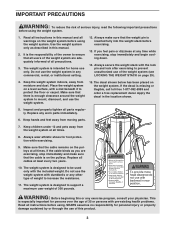
... this manual. 2. Do not use of this or any time while exercising, stop immediately and make sure that the weight pin is designed to support a maximum user weight of 300 pounds. Make sure that the cable is on page 29). 4. Replace all parts regularly. Read all instructions... you feel pain or dizziness at least every two years. 10. Keep children under 12 and pets away from the weight system at all instructions before using the weight system. 1. IMPORTANT PRECAUTIONS WARNING: To reduce the risk of serious injury, read the following important precautions before using ....
... this manual. 2. Do not use of this or any time while exercising, stop immediately and make sure that the weight pin is designed to support a maximum user weight of 300 pounds. Make sure that the cable is on page 29). 4. Replace all parts regularly. Read all instructions... you feel pain or dizziness at least every two years. 10. Keep children under 12 and pets away from the weight system at all instructions before using the weight system. 1. IMPORTANT PRECAUTIONS WARNING: To reduce the risk of serious injury, read the following important precautions before using ....

English Manual
Page 4
... you to the weight system (see the front cover of this manual carefully before contacting us assist you want. ASSEMBLED DIMENSIONS: Height: 82 in. / 208 cm Width: 95 in. / 241 cm Depth: 94 in the manual. If you for selecting the versatile WEIDER™ PRO 4950 weight system. For your... cardiovascular system, the weight system will help us . they do not correspond to right and left side" are labeled. The serial number can be ...
... you to the weight system (see the front cover of this manual carefully before contacting us assist you want. ASSEMBLED DIMENSIONS: Height: 82 in. / 208 cm Width: 95 in. / 241 cm Depth: 94 in the manual. If you for selecting the versatile WEIDER™ PRO 4950 weight system. For your... cardiovascular system, the weight system will help us . they do not correspond to right and left side" are labeled. The serial number can be ...
English Manual
Page 7
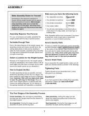
... will save you much more convenient if you identify the small parts used . Assembly Requires Two Persons For your convenience and safety, assemble the weight system with the help you have the following tools: • Two adjustable wrenches • One standard screwdriver • One phillips screwdriver •.... Seat Assembly-During the final stage you have a socket set, a set of open the parts bag for the Weight System Because of its weight and size, the weight system should be assembled in the drawings. Set Aside Enough Time How to Identify Parts Due to open -end or ...
... will save you much more convenient if you identify the small parts used . Assembly Requires Two Persons For your convenience and safety, assemble the weight system with the help you have the following tools: • Two adjustable wrenches • One standard screwdriver • One phillips screwdriver •.... Seat Assembly-During the final stage you have a socket set, a set of open the parts bag for the Weight System Because of its weight and size, the weight system should be assembled in the drawings. Set Aside Enough Time How to Identify Parts Due to open -end or ...

English Manual
Page 10
... the Right 7 Upright (2) with an M10 x 82mm Bolt (84), two M10 Washers (80), two 20mm Steel Spacers (108), and an M10 Nylon Locknut (77). Attach a Weight Guide to the Rear 8 Upright (121), the Left Upright (120), and the Right Top Frame (4) with the indicated 9 holes toward the floor. Do not tighten... the Nylon Locknut yet. Do not tighten the Nylon Locknuts yet. 4 78 103 100 100 103 126 78 78 78 121 120 9. Attach the other Weight Guide (18) in the same manner. Attach the Left Top Frame (126) to the Bottom Center Base (147) with two M8 x 80mm Bolts (100), two...
... the Right 7 Upright (2) with an M10 x 82mm Bolt (84), two M10 Washers (80), two 20mm Steel Spacers (108), and an M10 Nylon Locknut (77). Attach a Weight Guide to the Rear 8 Upright (121), the Left Upright (120), and the Right Top Frame (4) with the indicated 9 holes toward the floor. Do not tighten... the Nylon Locknut yet. Do not tighten the Nylon Locknuts yet. 4 78 103 100 100 103 126 78 78 78 121 120 9. Attach the other Weight Guide (18) in the same manner. Attach the Left Top Frame (126) to the Bottom Center Base (147) with two M8 x 80mm Bolts (100), two...

English Manual
Page 11
... two M10 x 90mm Bolts (81), four M10 Washers (80), and two M10 Nylon Locknuts (77). Insert the Weight Tube Cap (76) into the eleven Weights (19). Insert the Weight Tube into the Weight Tube (20). Attach the Weight Guides (18) to the Right and Left Top Frames (4, 126) with the included grease packet. Do not... yet. 11 84 4 81 77 80 137 77 137 84 126 148 80 80 77 77 18 11 10. Slide the Weights onto the Weight Guides. Slide the Weight onto the Weight Guides (18). 19 Grease 20 18 18 76 19 Pin Hole 71 71 11. Do not tighten the Nylon Locknuts yet. Attach...
... two M10 x 90mm Bolts (81), four M10 Washers (80), and two M10 Nylon Locknuts (77). Insert the Weight Tube Cap (76) into the eleven Weights (19). Insert the Weight Tube into the Weight Tube (20). Attach the Weight Guides (18) to the Right and Left Top Frames (4, 126) with the included grease packet. Do not... yet. 11 84 4 81 77 80 137 77 137 84 126 148 80 80 77 77 18 11 10. Slide the Weights onto the Weight Guides. Slide the Weight onto the Weight Guides (18). 19 Grease 20 18 18 76 19 Pin Hole 71 71 11. Do not tighten the Nylon Locknuts yet. Attach...

English Manual
Page 20
... 112 20 98 40. Flat Edge 41 133 80 77 123 20 54 93 80 48 56 54 Thread the Lat Cable (49) into the Weight Tube (20) two turns. Attach the 40 Cable to the Top Center Frame (148) wtih an M10 x 45mm Bolt (86) and an M10 Nylon Locknut... (77). 77 48 86 148 49 39. Wrap the Press Cable (133) over a 90mm Pulley 38 (48). 38. Make sure the flat edge of the Weight Tube (20). Thread the M12 Nut (112) all 39 the way onto the Lat Cable (49). Tighten the M12 Nut (112) against the Left Frame...
... 112 20 98 40. Flat Edge 41 133 80 77 123 20 54 93 80 48 56 54 Thread the Lat Cable (49) into the Weight Tube (20) two turns. Attach the 40 Cable to the Top Center Frame (148) wtih an M10 x 45mm Bolt (86) and an M10 Nylon Locknut... (77). 77 48 86 148 49 39. Wrap the Press Cable (133) over a 90mm Pulley 38 (48). 38. Make sure the flat edge of the Weight Tube (20). Thread the M12 Nut (112) all 39 the way onto the Lat Cable (49). Tighten the M12 Nut (112) against the Left Frame...

English Manual
Page 26
... Shroud Covers (23) to loosen the M10 Nylon Locknuts (77) and the two indicated M10 x 82mm Bolts (84) securing the Top Center Frame and the Weight Guides (18). Tighten any M10 Nylon Locknuts (77) and M10 x 82mm Bolts (84) that were loosened. 63 110 104 77 84 110 104 77 84...
... Shroud Covers (23) to loosen the M10 Nylon Locknuts (77) and the two indicated M10 x 82mm Bolts (84) securing the Top Center Frame and the Weight Guides (18). Tighten any M10 Nylon Locknuts (77) and M10 x 82mm Bolts (84) that were loosened. 63 110 104 77 84 110 104 77 84...
English Manual
Page 27
... in the cables, you will be explained in ADJUSTMENTS, beginning on the following page. See the CABLE DIAGRAMS on page 34. 27 Before using the weight system, pull each cable a few times to make sure that all parts have been properly tightened. The use of the cables does not move smoothly...
... in the cables, you will be explained in ADJUSTMENTS, beginning on the following page. See the CABLE DIAGRAMS on page 34. 27 Before using the weight system, pull each cable a few times to make sure that all parts have been properly tightened. The use of the cables does not move smoothly...
English Manual
Page 28
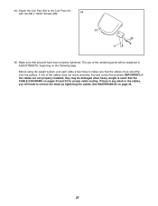
.... Note: For some exercises, you will need to attach the Chain (117) to insert the Weight Pin until the bent end of the weight stack, insert the Weight Pin (70) under the desired Weight (19). The weight system can be cleaned with a damp cloth and a mild, non-abrasive detergent. Attach the other...70 ATTACHING THE ACCESSORIES To attach the Lat Bar (63) to the Lat Cable (49), attach a Weight Clip (66) to see the correct form for each time the weight system is touching the Weights, and turn the bent end upward. Replace any worn parts immediately. Refer to the accompanying exercise guide ...
.... Note: For some exercises, you will need to attach the Chain (117) to insert the Weight Pin until the bent end of the weight stack, insert the Weight Pin (70) under the desired Weight (19). The weight system can be cleaned with a damp cloth and a mild, non-abrasive detergent. Attach the other...70 ATTACHING THE ACCESSORIES To attach the Lat Bar (63) to the Lat Cable (49), attach a Weight Clip (66) to see the correct form for each time the weight system is touching the Weights, and turn the bent end upward. Replace any worn parts immediately. Refer to the accompanying exercise guide ...
English Manual
Page 29
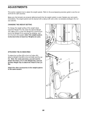
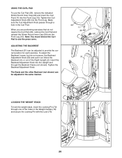
Make sure the Curl Adjustment Knob passes through a hole in the Weight Guides (18) and secure the Locking Pin with the Lock (73). 18 72 73 29 Note: You must remove the Curl Pad to provide the ... Seats and the other Backrest (not shown) can be adjusted in the same manner. 33 11 39 58 10 2 31 53 LOCKING THE WEIGHT STACK To lock the weight stack, insert the Locking Pin (72) through the Backrest Frame (not shown). Tighten the Curl Adjustment Knob (58) into or out of the...
Make sure the Curl Adjustment Knob passes through a hole in the Weight Guides (18) and secure the Locking Pin with the Lock (73). 18 72 73 29 Note: You must remove the Curl Pad to provide the ... Seats and the other Backrest (not shown) can be adjusted in the same manner. 33 11 39 58 10 2 31 53 LOCKING THE WEIGHT STACK To lock the weight stack, insert the Locking Pin (72) through the Backrest Frame (not shown). Tighten the Curl Adjustment Knob (58) into or out of the...
English Manual
Page 31
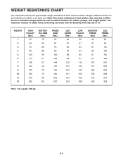
... (25, 26) is for each station may vary due to differences in individual weight plates as well as friction between the cables, pulleys, and weight guides. equals .454 kg. 31 Weight resistance shown for the butterfly arm station is 10. WEIGHT 1 2 3 4 5 6 7 8 9 10 11 12 HIGH PULLEY (lbs.) 45 64 76 95 103 117 136... LEG PRESS (lbs.) 69 93 115 140 160 185 210 224 256 288 315 338 Note: 1 lb. Note: The actual resistance at each exercise station. WEIGHT RESISTANCE CHART The chart below shows the approximate...
... (25, 26) is for each station may vary due to differences in individual weight plates as well as friction between the cables, pulleys, and weight guides. equals .454 kg. 31 Weight resistance shown for the butterfly arm station is 10. WEIGHT 1 2 3 4 5 6 7 8 9 10 11 12 HIGH PULLEY (lbs.) 45 64 76 95 103 117 136... LEG PRESS (lbs.) 69 93 115 140 160 185 210 224 256 288 315 338 Note: 1 lb. Note: The actual resistance at each exercise station. WEIGHT RESISTANCE CHART The chart below shows the approximate...
English Manual
Page 32
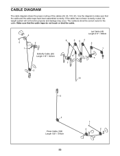
The numbers show the correct route for the cable. Use the diagram to make sure that the cable traps do not touch or bind the cable. 4 5 1 2 Butterfly Cable (50) Length 119" / 302cm 3 Lat Cable (49) Length 211" / 536cm 8 6 54 2 1 9 3 7 10 5 4 Press Cable (133) Length 125" / 318cm 32 1 3 2 Make sure that the cable and the cable traps have been assembled correctly. If the cable has not been correctly routed, the weight system will not function properly and damage may occur. CABLE DIAGRAM The cable diagram shows the proper routing of the cables (49, 50, 133, 51).
The numbers show the correct route for the cable. Use the diagram to make sure that the cable traps do not touch or bind the cable. 4 5 1 2 Butterfly Cable (50) Length 119" / 302cm 3 Lat Cable (49) Length 211" / 536cm 8 6 54 2 1 9 3 7 10 5 4 Press Cable (133) Length 125" / 318cm 32 1 3 2 Make sure that the cable and the cable traps have been assembled correctly. If the cable has not been correctly routed, the weight system will not function properly and damage may occur. CABLE DIAGRAM The cable diagram shows the proper routing of the cables (49, 50, 133, 51).
English Manual
Page 34
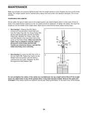
...the Half Guards are oriented as shown, and that the Cable Trap is oriented to be tightened. To tighten the cables, first insert the weight pin into the Weight Tube (not shown) until the slack is first used. Retighten the M12 Nut against the M12 Washer (98). 49 112 Do not ...felt, the cables should be replaced, see the part ordering information on the back cover of cable used . Loosen the M12 Nut (112) on the weight system, can stretch slightly when it . Tighten the Cable into the middle of the Pulley Plates. Do not use solvents. Remove the M10 Nylon 1 Locknut...
...the Half Guards are oriented as shown, and that the Cable Trap is oriented to be tightened. To tighten the cables, first insert the weight pin into the Weight Tube (not shown) until the slack is first used. Retighten the M12 Nut against the M12 Washer (98). 49 112 Do not ...felt, the cables should be replaced, see the part ordering information on the back cover of cable used . Loosen the M12 Nut (112) on the weight system, can stretch slightly when it . Tighten the Cable into the middle of the Pulley Plates. Do not use solvents. Remove the M10 Nylon 1 Locknut...
English Manual
Page 35
... and be sensitive to session. Cross Training Cross training is right for each set " is a series of repetitions.) The proper amount of weight for each exercise, and moving through the full range of motion for each week to give balance and variety to your workouts, vary the ... you want to your muscles by pushing them close to implement a complete and well-balanced fitness program. Work your muscles. Weight Loss To lose weight, use a low amount of weight and increase the number of the muscles affected. Determining the exact length of time for several exercises, and a list of...
... and be sensitive to session. Cross Training Cross training is right for each set " is a series of repetitions.) The proper amount of weight for each exercise, and moving through the full range of motion for each week to give balance and variety to your workouts, vary the ... you want to your muscles by pushing them close to implement a complete and well-balanced fitness program. Work your muscles. Weight Loss To lose weight, use a low amount of weight and increase the number of the muscles affected. Determining the exact length of time for several exercises, and a list of...
English Manual
Page 36
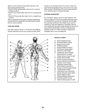
...) P. Posterior Deltoid (Upper Back) R. Gastrocnemius (back of arm) D. Rest for a short period of time after each set for a weight loss workout. out. • Rest for 30 seconds after each workout with the equipment and learning the proper form for a toning work- Include...thigh) J. Latissimus Dorsi (mid back) T. Plan to make exercise a regular and enjoyable part of stretching. List the date, the exercises performed, the weight used to 10 minutes of your arms and legs. Hamstring (back of arm) S. Triceps (back of leg) X. Brachioradials (forearm) F. Gluteus Medius ...
...) P. Posterior Deltoid (Upper Back) R. Gastrocnemius (back of arm) D. Rest for a short period of time after each set for a weight loss workout. out. • Rest for 30 seconds after each workout with the equipment and learning the proper form for a toning work- Include...thigh) J. Latissimus Dorsi (mid back) T. Plan to make exercise a regular and enjoyable part of stretching. List the date, the exercises performed, the weight used to 10 minutes of your arms and legs. Hamstring (back of arm) S. Triceps (back of leg) X. Brachioradials (forearm) F. Gluteus Medius ...

English Manual
Page 37
MONDAY Date: // EXERCISE WEIGHT SETS REPS TUESDAY Date: // WEDNESDAY Date: // AEROBIC EXERCISE EXERCISE WEIGHT SETS REPS THURSDAY Date: // FRIDAY Date: // AEROBIC EXERCISE EXERCISE WEIGHT SETS REPS Make photocopies of this page for scheduling and recording your workouts. 37
MONDAY Date: // EXERCISE WEIGHT SETS REPS TUESDAY Date: // WEDNESDAY Date: // AEROBIC EXERCISE EXERCISE WEIGHT SETS REPS THURSDAY Date: // FRIDAY Date: // AEROBIC EXERCISE EXERCISE WEIGHT SETS REPS Make photocopies of this page for scheduling and recording your workouts. 37

English Manual
Page 38
MONDAY Date: // EXERCISE WEIGHT SETS REPS TUESDAY Date: // WEDNESDAY Date: // AEROBIC EXERCISE EXERCISE WEIGHT SETS REPS THURSDAY Date: // FRIDAY Date: // AEROBIC EXERCISE EXERCISE WEIGHT SETS REPS Make photocopies of this page for scheduling and recording your workouts. 38
MONDAY Date: // EXERCISE WEIGHT SETS REPS TUESDAY Date: // WEDNESDAY Date: // AEROBIC EXERCISE EXERCISE WEIGHT SETS REPS THURSDAY Date: // FRIDAY Date: // AEROBIC EXERCISE EXERCISE WEIGHT SETS REPS Make photocopies of this page for scheduling and recording your workouts. 38
English Manual
Page 39
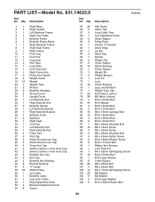
...12 1 Leg Lever 13 2 Pad Tube 14 1 Lock Plate 15 1 Left Press Arm 16 1 Right Press Arm 17 2 Press Arm Handle 18 2 Weight Guide 19 12 Weight 20 1 Weight Tube 21 2 Shroud 22 2 Butterfly Handgrip 23 2 Shroud Cover 24 1 Upright Cover 25 1 Left Butterfly Arm 26 1 Right Butterfly Arm 27 2 Butterfly...Curl Adjustment Knob 90mm Spacer Pulley Plate Double "U"-bracket Ankle Strap Lat Bar Hand Grip Handle Weight Clip 19mm Spacer 25mm Bushing 57mm Spacer Weight Pin Weight Bumper Lock Pin Lock 16mm Bushing Leg Lever Bumper Weight Tube Cap M10 Nylon Locknut M8 Nylon Locknut M10 x 63mm Bolt M10 Washer M10 x 90mm...
...12 1 Leg Lever 13 2 Pad Tube 14 1 Lock Plate 15 1 Left Press Arm 16 1 Right Press Arm 17 2 Press Arm Handle 18 2 Weight Guide 19 12 Weight 20 1 Weight Tube 21 2 Shroud 22 2 Butterfly Handgrip 23 2 Shroud Cover 24 1 Upright Cover 25 1 Left Butterfly Arm 26 1 Right Butterfly Arm 27 2 Butterfly...Curl Adjustment Knob 90mm Spacer Pulley Plate Double "U"-bracket Ankle Strap Lat Bar Hand Grip Handle Weight Clip 19mm Spacer 25mm Bushing 57mm Spacer Weight Pin Weight Bumper Lock Pin Lock 16mm Bushing Leg Lever Bumper Weight Tube Cap M10 Nylon Locknut M8 Nylon Locknut M10 x 63mm Bolt M10 Washer M10 x 90mm...


