

English Manual
Page 1
Save this equipment. WEIGHT SYSTEM EXERCISER User's Manual Serial Number Decal (under seat) • Assembly • Adjustments • Troubleshooting • Part List and Drawing CAUTION Read all precautions and instructions in the space above for future reference. Patent Pending Sears, Roebuck and Co., Hoffman Estates, IL 60179 Model No. 831.159301 Serial No. Write the serial number in this manual before using this manual for reference.
Save this equipment. WEIGHT SYSTEM EXERCISER User's Manual Serial Number Decal (under seat) • Assembly • Adjustments • Troubleshooting • Part List and Drawing CAUTION Read all precautions and instructions in the space above for future reference. Patent Pending Sears, Roebuck and Co., Hoffman Estates, IL 60179 Model No. 831.159301 Serial No. Write the serial number in this manual before using this manual for reference.

English Manual
Page 2
TABLE OF CONTENTS IMPORTANT PRECAUTIONS 3 BEFORE YOU BEGIN 4 ASSEMBLY 5 ADJUSTMENTS 13 WEIGHT RESISTANCE CHART 15 TROUBLESHOOTING 16 CABLE DIAGRAMS 17 EXERCISE GUIDELINES 18 ORDERING REPLACEMENT PARTS Back Cover FULL 90-DAY WARRANTY Back Cover Note: A PART IDENTIFICATION CHART and a PART LIST/EXPLODED DRAWING are attached to the center of this manual. Remove the PART IDENTIFICATION CHART and PART LIST/EXPLODED DRAWING before beginning assembly. 2
TABLE OF CONTENTS IMPORTANT PRECAUTIONS 3 BEFORE YOU BEGIN 4 ASSEMBLY 5 ADJUSTMENTS 13 WEIGHT RESISTANCE CHART 15 TROUBLESHOOTING 16 CABLE DIAGRAMS 17 EXERCISE GUIDELINES 18 ORDERING REPLACEMENT PARTS Back Cover FULL 90-DAY WARRANTY Back Cover Note: A PART IDENTIFICATION CHART and a PART LIST/EXPLODED DRAWING are attached to the center of this manual. Remove the PART IDENTIFICATION CHART and PART LIST/EXPLODED DRAWING before beginning assembly. 2

English Manual
Page 3
Read all times. 12. Use the weight system only on the pulleys at 1-877-992-5999 and order a free replacement decal. Keep children under 12 and pets away from the weight system when performing an exercise that does not use the weight system in the location shown. 7. If you are on the weight system in the accompanying literature before using the weight system. 2. The decals shown below have been placed on all times. If a decal is designed to ensure that the cables are exercising, stop immediately and begin cooling down. 15. Always stand on page 4. Decal 1 WARNING: ...
Read all times. 12. Use the weight system only on the pulleys at 1-877-992-5999 and order a free replacement decal. Keep children under 12 and pets away from the weight system when performing an exercise that does not use the weight system in the location shown. 7. If you are on the weight system in the accompanying literature before using the weight system. 2. The decals shown below have been placed on all times. If a decal is designed to ensure that the cables are exercising, stop immediately and begin cooling down. 15. Always stand on page 4. Decal 1 WARNING: ...

English Manual
Page 4
... and familiarize yourself with the parts that are determined relative to the weight system (see the front cover of this manual for selecting the versatile WEIDER® PRO 2250 weight system. they do not correspond to right and left side" are labeled. BEFORE YOU BEGIN Thank you want. If you , please note the...
... and familiarize yourself with the parts that are determined relative to the weight system (see the front cover of this manual for selecting the versatile WEIDER® PRO 2250 weight system. they do not correspond to right and left side" are labeled. BEFORE YOU BEGIN Thank you want. If you , please note the...

English Manual
Page 5
Frame Assembly 1 1. Note: It may be helpful to place a piece of tape over the bolt heads to ensure that you assemble them, unless instructed to the Stabilizer (5) with the small holes on the indicated side. ASSEMBLY Make Things Easier for assembly: • Two adjustable wrenches • One rubber mallet • One standard screwdriver • One Phillips screwdriver • Lubricant, such as grease or petroleum jelly, and soapy water. The following tools (not included) are oriented as you have a socket set, a set of open-end or closed-end wrenches, or a set of this ...
Frame Assembly 1 1. Note: It may be helpful to place a piece of tape over the bolt heads to ensure that you assemble them, unless instructed to the Stabilizer (5) with the small holes on the indicated side. ASSEMBLY Make Things Easier for assembly: • Two adjustable wrenches • One rubber mallet • One standard screwdriver • One Phillips screwdriver • Lubricant, such as grease or petroleum jelly, and soapy water. The following tools (not included) are oriented as you have a socket set, a set of open-end or closed-end wrenches, or a set of this ...

English Manual
Page 6
Stack the six Weights (25) on the same side of the Weights are turned so the large pin grooves are resting in the pin grooves in the Top Weight (76). Make sure that the pins on the Weight Tube are on the bottom of the Weights and on the Weight Bumpers (19). Do not tighten the Locknuts yet. 42 3 3. Tighten the M10 Nylon Locknuts (21) used in the Base (4). Press the Weight Tube Bumper (64) into the stack of the holes in the upper Weight. Attach the two Weight Guides (62) inside of the Weight Tube (63). Insert the Weight Tube into the end of the 3 Stabilizer...
Stack the six Weights (25) on the same side of the Weights are turned so the large pin grooves are resting in the pin grooves in the Top Weight (76). Make sure that the pins on the Weight Tube are on the bottom of the Weights and on the Weight Bumpers (19). Do not tighten the Locknuts yet. 42 3 3. Tighten the M10 Nylon Locknuts (21) used in the Base (4). Press the Weight Tube Bumper (64) into the stack of the holes in the upper Weight. Attach the two Weight Guides (62) inside of the Weight Tube (63). Insert the Weight Tube into the end of the 3 Stabilizer...

English Manual
Page 7
Lubricate the M10 x 198mm Bolt (59) with the Bolt, two M10 Washers (9), and an M10 Nylon Locknut (21). 4. Press two 25mm Plastic Bushings (75) onto the welded spacers on the Base (4) as shown. Slide the Press Frame into place on the Press Frame (17). Attach the Press Frame (17) to the indicated side of the indicated tube in the same manner. 5 Hole 17 21 9 Welded Spacer 75 4 9 Tube Lubricate 59 6 46 73 Holes 22 9 17 9 22 21 9 21 7 Identify the Right and Left Press Arms (46, 73) by the position of the Weight Guides (62) to pivot easily. 6. Do not overtighten the ...
Lubricate the M10 x 198mm Bolt (59) with the Bolt, two M10 Washers (9), and an M10 Nylon Locknut (21). 4. Press two 25mm Plastic Bushings (75) onto the welded spacers on the Base (4) as shown. Slide the Press Frame into place on the Press Frame (17). Attach the Press Frame (17) to the indicated side of the indicated tube in the same manner. 5 Hole 17 21 9 Welded Spacer 75 4 9 Tube Lubricate 59 6 46 73 Holes 22 9 17 9 22 21 9 21 7 Identify the Right and Left Press Arms (46, 73) by the position of the Weight Guides (62) to pivot easily. 6. Do not overtighten the ...

English Manual
Page 8
Make sure that the end of the Pulley. 42 21 9 15 66 71 58 8 Locate the Short Cable (58). Lay the Cable in the groove of the Cable with soapy water and slide a Large Pad (45) onto it. Identify the Right Arm (48) and the Left Arm (47) 7 by the position of a 25mm Round Cover Cap (70). Set two 25mm Retainers (69) on top of the welded bracket on each Arm. Make sure that the Cable Trap is behind the indicated bracket on the Base (4) and under a 90mm Pulley 9 (15) Attach the Pulley and a Cable Trap (66) to confuse the Right Arm (48) with the Left Arm. Make sure ...
Make sure that the end of the Pulley. 42 21 9 15 66 71 58 8 Locate the Short Cable (58). Lay the Cable in the groove of the Cable with soapy water and slide a Large Pad (45) onto it. Identify the Right Arm (48) and the Left Arm (47) 7 by the position of a 25mm Round Cover Cap (70). Set two 25mm Retainers (69) on top of the welded bracket on each Arm. Make sure that the Cable Trap is behind the indicated bracket on the Base (4) and under a 90mm Pulley 9 (15) Attach the Pulley and a Cable Trap (66) to confuse the Right Arm (48) with the Left Arm. Make sure ...

English Manual
Page 9
Tighten the M10 x 80mm Bolt (16), the M10 Washer (9), and the M10 Nylon Locknut (21). 10 21 15 58 17 9 16 11. Make sure that the Cable Trap is turned to the Long "U"-bracket (57) with an M10 x 95mm Bolt (71), an M10 Washer (9), and an M10 Nylon Locknut (21). it should be threaded onto the end of the Cable so that the end of the Cable with the ball is between the Pulley and the hook and that two threads are showing above the nut. 12 3 57 8 58 13. Route the Short Cable (58) under a 90mm Pulley 11 (15). Attach the end of the Pulley. 42 21 9 58 15 66 71 12. Locate the ...
Tighten the M10 x 80mm Bolt (16), the M10 Washer (9), and the M10 Nylon Locknut (21). 10 21 15 58 17 9 16 11. Make sure that the Cable Trap is turned to the Long "U"-bracket (57) with an M10 x 95mm Bolt (71), an M10 Washer (9), and an M10 Nylon Locknut (21). it should be threaded onto the end of the Cable so that the end of the Cable with the ball is between the Pulley and the hook and that two threads are showing above the nut. 12 3 57 8 58 13. Route the Short Cable (58) under a 90mm Pulley 11 (15). Attach the end of the Pulley. 42 21 9 58 15 66 71 12. Locate the ...

English Manual
Page 10
Attach the "V"-pulley and a Long Cable Trap (50) to the Pulley Bracket (20). Repeat this step with an M10 x 48mm Bolt (12) and an M10 Nylon Locknut (21). Route the Long Cable (23) over a "V"-pulley (6). 14 Attach the "V"-pulley and a Long Cable Trap (50) to pivot easily. 17. Tighten the M10 x 48mm Bolt (12) and the M10 Nylon Locknut (21). the Pulley Bracket must be able to the Front Upright (42) with an M10 x 58mm Bolt (7) and an M10 Nylon Locknuts (21). Make sure that the Long Cable Trap is oriented to hold the Cable in the Long "U"-bracket (57) with the Right Arm (...
Attach the "V"-pulley and a Long Cable Trap (50) to the Pulley Bracket (20). Repeat this step with an M10 x 48mm Bolt (12) and an M10 Nylon Locknut (21). Route the Long Cable (23) over a "V"-pulley (6). 14 Attach the "V"-pulley and a Long Cable Trap (50) to pivot easily. 17. Tighten the M10 x 48mm Bolt (12) and the M10 Nylon Locknut (21). the Pulley Bracket must be able to the Front Upright (42) with an M10 x 58mm Bolt (7) and an M10 Nylon Locknuts (21). Make sure that the Long Cable Trap is oriented to hold the Cable in the Long "U"-bracket (57) with the Right Arm (...
English Manual
Page 11
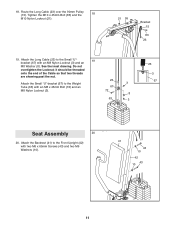
18. Route the Long Cable (23) over the 90mm Pulley (15). Attach the Long Cable (23) to the Front Upright (42) with two M6 x 65mm Screws (43) and two M6 Washers (10). 41 43 10 42 43 10 11 Tighten the M10 x 45mm Bolt (83) and the 18 M10 Nylon Locknut (21). 21 55 Bracket 15 83 23 19. Attach the Backrest (41) to the Small "U"- 19 bracket (67) with an M8 x 45mm Bolt (72) and an 3 67 M8 Nylon Locknut (3). 72 8 63 3 23 3 67 Seat Assembly 20 20. See the inset drawing. it should be threaded onto the end of the Cable so that two threads are showing past the nut. 23 ...
18. Route the Long Cable (23) over the 90mm Pulley (15). Attach the Long Cable (23) to the Front Upright (42) with two M6 x 65mm Screws (43) and two M6 Washers (10). 41 43 10 42 43 10 11 Tighten the M10 x 45mm Bolt (83) and the 18 M10 Nylon Locknut (21). 21 55 Bracket 15 83 23 19. Attach the Backrest (41) to the Small "U"- 19 bracket (67) with an M8 x 45mm Bolt (72) and an 3 67 M8 Nylon Locknut (3). 72 8 63 3 23 3 67 Seat Assembly 20 20. See the inset drawing. it should be threaded onto the end of the Cable so that two threads are showing past the nut. 23 ...
English Manual
Page 12
21. Tighten an M6 Nylon Locknut (2) with the Bolt and an M8 Nylon Locknut (3). Attach the Leg Lever (29) to the Seat Frame (36) with an M6 Washer (10) and an M6 x 50mm Screw (24). 38 37 18 13 36 10 24 2 22. Insert a Pad Tube (28) into the Leg Lever (29) from the direction shown. Assemble the other end of the Seat (13) to the Seat Frame (36) with an M6 Washer (10) onto the Carriage Bolt. Rest the Seat Frame (36) on the indicated pin in the indicated position. Make sure the decal is in 24 the Front Upright (42). the Leg Lever must be able to the Seat (...
21. Tighten an M6 Nylon Locknut (2) with the Bolt and an M8 Nylon Locknut (3). Attach the Leg Lever (29) to the Seat Frame (36) with an M6 Washer (10) and an M6 x 50mm Screw (24). 38 37 18 13 36 10 24 2 22. Insert a Pad Tube (28) into the Leg Lever (29) from the direction shown. Assemble the other end of the Seat (13) to the Seat Frame (36) with an M6 Washer (10) onto the Carriage Bolt. Rest the Seat Frame (36) on the indicated pin in the indicated position. Make sure the decal is in 24 the Front Upright (42). the Leg Lever must be able to the Seat (...

English Manual
Page 13
The use of the remaining parts will be explained in ADJUSTMENTS, beginning below describe how each part of 12.5 pounds. See the CABLE DIAGRAMS on page 15 to the Short Cable (not shown) in increments of the weight system can be attached to find and correct the problem. If there is used with an accessory. (See ATTACHING AND REMOVING THE SEAT, on page 16. 25. For some exercises, the Chain (52) should be attached between the Lat Bar and the Cable so the Lat Bar is in the cables or chain as an exercise is any slack in the correct starting position for the ...
The use of the remaining parts will be explained in ADJUSTMENTS, beginning below describe how each part of 12.5 pounds. See the CABLE DIAGRAMS on page 15 to the Short Cable (not shown) in increments of the weight system can be attached to find and correct the problem. If there is used with an accessory. (See ATTACHING AND REMOVING THE SEAT, on page 16. 25. For some exercises, the Chain (52) should be attached between the Lat Bar and the Cable so the Lat Bar is in the cables or chain as an exercise is any slack in the correct starting position for the ...

English Manual
Page 14
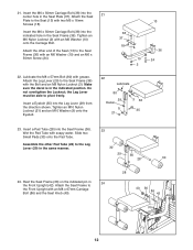
First, make sure that the Chain (not shown) is not attached to the Front Upright with a Cable Clip (53). ATTACHING THE LEG LEVER TO THE LOW PULLEY STATION To use the Leg Lever (29), the seat must also be removed when removing the Short Cable from the Eyebolt. 40 36 13 86 42 Pin 29 29 35 53 58 14 Next, remove the Seat Knob (40) and the M8 x 67mm Carriage Bolt (86) from the weight stack. Attach the Short Cable (58) to the front upright (see ATTACHING AND REMOVING THE SEAT, above). Lift the Seat Frame off the Front Upright (42). Note: The Weight Pin must be removed. ...
First, make sure that the Chain (not shown) is not attached to the Front Upright with a Cable Clip (53). ATTACHING THE LEG LEVER TO THE LOW PULLEY STATION To use the Leg Lever (29), the seat must also be removed when removing the Short Cable from the Eyebolt. 40 36 13 86 42 Pin 29 29 35 53 58 14 Next, remove the Seat Knob (40) and the M8 x 67mm Carriage Bolt (86) from the weight stack. Attach the Short Cable (58) to the front upright (see ATTACHING AND REMOVING THE SEAT, above). Lift the Seat Frame off the Front Upright (42). Note: The Weight Pin must be removed. ...
English Manual
Page 15
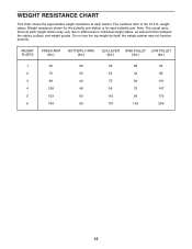
Note: The actual resistance at each station. WEIGHT PLATES PRESS ARM (lbs.) BUTTERFLY ARM (lbs.) LEG LEVER HIGH PULLEY LOW PULLEY (lbs.) (lbs.) (lbs.) 1 45 2 70 3 99 4 128 5 153 6 184 22 36 28 54 33 54 44 82 42 75 60 115 48 96 72 147 60 115 90 175 69 137 103 209 15 Weight resistance shown for the butterfly arm station is for each butterfly arm. Do not use the top weight by itself; The numbers refer to differences in individual weight plates, as well as friction between the cables, pulleys, and weight guides. weight plates. the weight ...
Note: The actual resistance at each station. WEIGHT PLATES PRESS ARM (lbs.) BUTTERFLY ARM (lbs.) LEG LEVER HIGH PULLEY LOW PULLEY (lbs.) (lbs.) (lbs.) 1 45 2 70 3 99 4 128 5 153 6 184 22 36 28 54 33 54 44 82 42 75 60 115 48 96 72 147 60 115 90 175 69 137 103 209 15 Weight resistance shown for the butterfly arm station is for each butterfly arm. Do not use the top weight by itself; The numbers refer to differences in individual weight plates, as well as friction between the cables, pulleys, and weight guides. weight plates. the weight ...

English Manual
Page 16
Do not use solvents. Slack can be removed by tightening the M8 Nylon Locknuts (3) at the end of the Long Cable (23) or at the end of this you may have become twisted. Remove the M10 Nylon Locknut (21) and the M10 x 48mm Bolt (12) from the cables by moving the 90mm Pulley (15) to remove the Small "U"bracket (67) from the Weight Tube (63) or remove the 90mm Pulley (15) from the Long "U"-bracket (57). 15 57 12 66 21 3 58 23 67 3 63 Make sure that the Cable and Pulley move smoothly. If the cables need to the lower hole in the cables before resistance is used . TIGHTENING ...
Do not use solvents. Slack can be removed by tightening the M8 Nylon Locknuts (3) at the end of the Long Cable (23) or at the end of this you may have become twisted. Remove the M10 Nylon Locknut (21) and the M10 x 48mm Bolt (12) from the cables by moving the 90mm Pulley (15) to remove the Small "U"bracket (67) from the Weight Tube (63) or remove the 90mm Pulley (15) from the Long "U"-bracket (57). 15 57 12 66 21 3 58 23 67 3 63 Make sure that the Cable and Pulley move smoothly. If the cables need to the lower hole in the cables before resistance is used . TIGHTENING ...

English Manual
Page 17
CABLE DIAGRAMS The cable diagrams show the correct route for each cable. The numbers show the proper routing of the Long Cable (23) and the Short Cable (58). Make sure that the two cables and the cable traps have not been correctly routed, the weight system will not function properly and damage may occur. If the cables have been assembled correctly. Use the diagram to make sure that the cable traps do not touch or bind the cables. 5 4 7 1 2 3 Long Cable (23) 6 5 8 Short Cable (58) 4 3 2 1 17
CABLE DIAGRAMS The cable diagrams show the correct route for each cable. The numbers show the proper routing of the Long Cable (23) and the Short Cable (58). Make sure that the two cables and the cable traps have not been correctly routed, the weight system will not function properly and damage may occur. If the cables have been assembled correctly. Use the diagram to make sure that the cable traps do not touch or bind the cables. 5 4 7 1 2 3 Long Cable (23) 6 5 8 Short Cable (58) 4 3 2 1 17

English Manual
Page 18
You must gauge your limits and select the amount of resistance that you . Complete as many sets of 15 to 20 repetitions as possible without difficulty, increase the amount of resistance. Work your muscles by completing more sets rather than by using high amounts of 8 repetitions for more oxygen to your muscles. CROSS TRAINING Cross training is right for you want to develop most. It is a series of repetitions.) The proper amount of resistance for at your own pace and be sensitive to your body's signals. Select exercises for 3 minutes after each workout, as well as the ...
You must gauge your limits and select the amount of resistance that you . Complete as many sets of 15 to 20 repetitions as possible without difficulty, increase the amount of resistance. Work your muscles by completing more sets rather than by using high amounts of 8 repetitions for more oxygen to your muscles. CROSS TRAINING Cross training is right for you want to develop most. It is a series of repetitions.) The proper amount of resistance for at your own pace and be sensitive to your body's signals. Select exercises for 3 minutes after each workout, as well as the ...

English Manual
Page 19
The ideal resting periods are: • Rest for three minutes after each set for a muscle building workout. • Rest for one minute after each workout with 5 to spend the first couple of weeks familiarizing yourself with the equipment and learning the proper form for each set. COOLING DOWN End each set for a weight loss workout. Stretching at the end of every month. Pectoralis Major (chest) C. Rhomboideus (upper back) Q. Record your weight and key body measurements at the end of each stretch gradually and go only as far as you can without strain. A B C D E F G H...
The ideal resting periods are: • Rest for three minutes after each set for a muscle building workout. • Rest for one minute after each workout with 5 to spend the first couple of weeks familiarizing yourself with the equipment and learning the proper form for each set. COOLING DOWN End each set for a weight loss workout. Stretching at the end of every month. Pectoralis Major (chest) C. Rhomboideus (upper back) Q. Record your weight and key body measurements at the end of each stretch gradually and go only as far as you can without strain. A B C D E F G H...
English Manual
Page 22
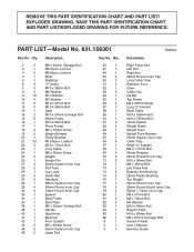
REMOVE THIS PART IDENTIFICATION CHART AND PART LIST/ EXPLODED DRAWING. Qty. 1 2 2 1 3 9 4 1 5 1 6 3 7 3 8 2 9 18 10 4 11 2 12 3 13 1 14 2 15 8 16 1 17 1 18 2 19 2 20 1 21 22 22 4 23 1 24 1 25 6 26 1 27 2 28 2 29 1 30 4 31 2 32 1 33 4 34 4 35 1 36 1 37 1 38 1 39 1 40 1 41 1 42 1 43 2 44 2 45 2 Description M8 x 65mm Carriage Bolt M6 Nylon Locknut M8 Nylon Locknut Base Stabilizer "V"-pulley M10 x 58mm Bolt M8 Washer M10 Washer M6 Washer M10 x 67mm Bolt M10 x 48mm Bolt Seat M10 x 67mm Carriage Bolt 90mm...
REMOVE THIS PART IDENTIFICATION CHART AND PART LIST/ EXPLODED DRAWING. Qty. 1 2 2 1 3 9 4 1 5 1 6 3 7 3 8 2 9 18 10 4 11 2 12 3 13 1 14 2 15 8 16 1 17 1 18 2 19 2 20 1 21 22 22 4 23 1 24 1 25 6 26 1 27 2 28 2 29 1 30 4 31 2 32 1 33 4 34 4 35 1 36 1 37 1 38 1 39 1 40 1 41 1 42 1 43 2 44 2 45 2 Description M8 x 65mm Carriage Bolt M6 Nylon Locknut M8 Nylon Locknut Base Stabilizer "V"-pulley M10 x 58mm Bolt M8 Washer M10 Washer M6 Washer M10 x 67mm Bolt M10 x 48mm Bolt Seat M10 x 67mm Carriage Bolt 90mm...