
Canadian English Manual
Page 1
... this manual before using this manual for future reference. Visit our website at www.weiderplatinum.com mitted to providing completewww.healthrider.com customer satisfaction. Save this equipment. Serial Number Decal (under seat) QUESTIONS? Visit our website at www.TheCrossBow.com Visit our website at www.imagefitness.com new products, prizes, fitness tips, and much more ! Model No. missing parts...
... this manual before using this manual for future reference. Visit our website at www.weiderplatinum.com mitted to providing completewww.healthrider.com customer satisfaction. Save this equipment. Serial Number Decal (under seat) QUESTIONS? Visit our website at www.TheCrossBow.com Visit our website at www.imagefitness.com new products, prizes, fitness tips, and much more ! Model No. missing parts...
Canadian English Manual
Page 2
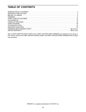
Remove the PART IDENTIFICATION CHART and PART LIST/EXPLODED DRAWING before beginning assembly. TABLE OF CONTENTS WARNING DECAL PLACEMENT 3 IMPORTANT PRECAUTIONS 4 BEFORE YOU BEGIN 5 ASSEMBLY 6 UPPER CABLE ADJUSTMENT 12 ADJUSTMENTS 13 CONSOLE OPERATION 16 CABLE DIAGRAM 18 TROUBLESHOOTING 19 EXERCISE GUIDELINES 20 ORDERING REPLACEMENT PARTS Back Cover LIMITED WARRANTY Back Cover Note: A PART IDENTIFICATION CHART and a PART LIST/EXPLODED DRAWING are attached in the center of ICON IP, Inc. 2 WEIDER is a registered trademark of this manual.
Remove the PART IDENTIFICATION CHART and PART LIST/EXPLODED DRAWING before beginning assembly. TABLE OF CONTENTS WARNING DECAL PLACEMENT 3 IMPORTANT PRECAUTIONS 4 BEFORE YOU BEGIN 5 ASSEMBLY 6 UPPER CABLE ADJUSTMENT 12 ADJUSTMENTS 13 CONSOLE OPERATION 16 CABLE DIAGRAM 18 TROUBLESHOOTING 19 EXERCISE GUIDELINES 20 ORDERING REPLACEMENT PARTS Back Cover LIMITED WARRANTY Back Cover Note: A PART IDENTIFICATION CHART and a PART LIST/EXPLODED DRAWING are attached in the center of ICON IP, Inc. 2 WEIDER is a registered trademark of this manual.
Canadian English Manual
Page 4
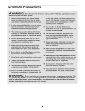
... designed to support a maximum user weight of all precautions. 3. Cover the floor beneath the resistance system to be used . Always wear athletic shoes for home use the resistance system in one of 35 or persons with any exercise program, consult your physician. The crossbar on the cables while the resistance level is used with the seat in any worn parts immediately. 6. Always disconnect the lat bar from the...
... designed to support a maximum user weight of all precautions. 3. Cover the floor beneath the resistance system to be used . Always wear athletic shoes for home use the resistance system in one of 35 or persons with any exercise program, consult your physician. The crossbar on the cables while the resistance level is used with the seat in any worn parts immediately. 6. Always disconnect the lat bar from the...
Canadian English Manual
Page 5
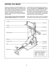
Crossbar Lat Bar Console Top Frame High Pulley Squat Backrest Resistance Bar Squat Pin Backrest Storage Knob Seat Leg Lever Low Pulley Row Plate Seat Knob Base Plate ASSEMBLED DIMENSIONS: Height: 218.4 cm (86 in.) Width: 127 cm (50 in.) Depth: 215.9 cm (85 in.) 5 The serial number can be found on a decal attached to develop every major muscle group of this manual, please call our toll-free customer service department at 1-888...
Crossbar Lat Bar Console Top Frame High Pulley Squat Backrest Resistance Bar Squat Pin Backrest Storage Knob Seat Leg Lever Low Pulley Row Plate Seat Knob Base Plate ASSEMBLED DIMENSIONS: Height: 218.4 cm (86 in.) Width: 127 cm (50 in.) Depth: 215.9 cm (85 in.) 5 The serial number can be found on a decal attached to develop every major muscle group of this manual, please call our toll-free customer service department at 1-888...
Canadian English Manual
Page 6
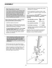
... a socket set, a set of open-end or closed-end wrenches, or a set of the Upright (2). tion in the drawings. Attach the Upright (2) to ensure that 1 you assemble the resistance system, make sure that the resistance system can be more convenient if you assemble them, unless instructed to realize that the versatile resistance system has many parts and that by most people. Pull the lower end...
... a socket set, a set of open-end or closed-end wrenches, or a set of the Upright (2). tion in the drawings. Attach the Upright (2) to ensure that 1 you assemble the resistance system, make sure that the resistance system can be more convenient if you assemble them, unless instructed to realize that the versatile resistance system has many parts and that by most people. Pull the lower end...
Canadian English Manual
Page 7
... shown in the inset drawing. Tighten the 1/2" x 25mm Screw (85). 3. Attach 3 the Leg to the Upright (2) with a 1/2" x 25mm Screw (85) and a 1/2" Lock Washer (12). Insert the connector of the Lower Wire Harness 2 (117). IF THE CONNECTOR IS NOT INSERTED PROPERLY, THE CONSOLE MAY BE DAMAGED WHEN THE POWER IS TURNED ON. Press the Rail Cap (49) onto the Leg (5). 2. If the connector does...
... shown in the inset drawing. Tighten the 1/2" x 25mm Screw (85). 3. Attach 3 the Leg to the Upright (2) with a 1/2" x 25mm Screw (85) and a 1/2" Lock Washer (12). Insert the connector of the Lower Wire Harness 2 (117). IF THE CONNECTOR IS NOT INSERTED PROPERLY, THE CONSOLE MAY BE DAMAGED WHEN THE POWER IS TURNED ON. Press the Rail Cap (49) onto the Leg (5). 2. If the connector does...
Canadian English Manual
Page 9
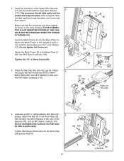
... (13) used in steps 8 and 9 (see the CABLE DIAGRAM on the Cable into the groove in steps 8 and 9. 10. Do not tighten the Bolt yet. 121 11 90 13 68 81 14 2 17 18 86 15 Metal 2 121 Cover 54 86 70 18 16 Groove 9 Pull the Upper Cable (121), which is between the Upright (2) and the Pulley Plate (68). Attach a Small Guide Spacer...
... (13) used in steps 8 and 9 (see the CABLE DIAGRAM on the Cable into the groove in steps 8 and 9. 10. Do not tighten the Bolt yet. 121 11 90 13 68 81 14 2 17 18 86 15 Metal 2 121 Cover 54 86 70 18 16 Groove 9 Pull the Upper Cable (121), which is between the Upright (2) and the Pulley Plate (68). Attach a Small Guide Spacer...
Canadian English Manual
Page 10
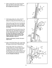
... Leg Station Pin (60). Press a Pulley Bracket (10) onto the Resistance Bar (9). Hold a Large Pulley (14) inside of the Upper Cable (121). Screw a 3/8" x 38mm Tension Screw (114) into the Pulley Bracket a couple of turns. 14. Attach a Tether (70) to the Leg (5) with an M10 x 64mm Button Bolt (80), an M10 Thick Washer (54), and an M10 Nylon Locknut (103). Tighten the two 3/8" x 38mm Tension Screws (114) an equal number...
... Leg Station Pin (60). Press a Pulley Bracket (10) onto the Resistance Bar (9). Hold a Large Pulley (14) inside of the Upper Cable (121). Screw a 3/8" x 38mm Tension Screw (114) into the Pulley Bracket a couple of turns. 14. Attach a Tether (70) to the Leg (5) with an M10 x 64mm Button Bolt (80), an M10 Thick Washer (54), and an M10 Nylon Locknut (103). Tighten the two 3/8" x 38mm Tension Screws (114) an equal number...
Canadian English Manual
Page 11
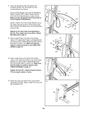
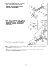
... the Seat Carriage and 32 slide the rod into the 16 slot in the inset drawing. 15. Slide a Pad Tube (50) into the Leg (5). Attach the other Pad Tube (50) to the Leg Lever (56) in UPPER CABLE ADJUSTMENT on page 13. Rod Slot 44 32 44 17. Before using the resistance system, turn on the console and change the resistance setting as...
... the Seat Carriage and 32 slide the rod into the 16 slot in the inset drawing. 15. Slide a Pad Tube (50) into the Leg (5). Attach the other Pad Tube (50) to the Leg Lever (56) in UPPER CABLE ADJUSTMENT on page 13. Rod Slot 44 32 44 17. Before using the resistance system, turn on the console and change the resistance setting as...
Canadian English Manual
Page 12
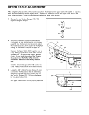
... in the resistance system as shown. Alternately tighten each end of the Pulley Bracket (10). Squeeze the Upper Cable (121) together near a Large Pulley (14). UPPER CABLE ADJUSTMENT After completing the assembly of the Tension Gauges (115, 116) around the Tether (70), which is attached to the back of the Resistance Bar (9). Plug in PLUGGING IN THE RESISTANCE SYSTEM on the upper cable will need to...
... in the resistance system as shown. Alternately tighten each end of the Pulley Bracket (10). Squeeze the Upper Cable (121) together near a Large Pulley (14). UPPER CABLE ADJUSTMENT After completing the assembly of the Tension Gauges (115, 116) around the Tether (70), which is attached to the back of the Resistance Bar (9). Plug in PLUGGING IN THE RESISTANCE SYSTEM on the upper cable will need to...
Canadian English Manual
Page 13
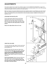
... how to the Leg (5) with a Leg Station Pin (60). Make sure all parts are properly tightened each exercise. Replace worn parts immediately. Route the hook end of the Lower Cable (120) with a Cable Clip (94). Attach a long end of the Leg Lever Cable (102) to one end of the Leg Lever Cable (102) under the Cable. Attach the other high pulley in the Leg (5), and attach it to adjust the resistance system. Attach the other...
... how to the Leg (5) with a Leg Station Pin (60). Make sure all parts are properly tightened each exercise. Replace worn parts immediately. Route the hook end of the Lower Cable (120) with a Cable Clip (94). Attach a long end of the Leg Lever Cable (102) to one end of the Leg Lever Cable (102) under the Cable. Attach the other high pulley in the Leg (5), and attach it to adjust the resistance system. Attach the other...
Canadian English Manual
Page 14
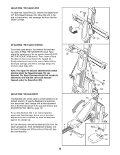
... a Squat Pin (66) into the Squat Carriage. 27 19 ATTACHING THE SQUAT STATION To use the Backrest in a level position, secure the Seat Carriage (44) at one of the Lower Cable (120) to descend so low that the user could become trapped under the Squat Arm (20). Finally, attach each end of the other adjustment holes in the Upright (2). Move the Arm to...
... a Squat Pin (66) into the Squat Carriage. 27 19 ATTACHING THE SQUAT STATION To use the Backrest in a level position, secure the Seat Carriage (44) at one of the Lower Cable (120) to descend so low that the user could become trapped under the Squat Arm (20). Finally, attach each end of the other adjustment holes in the Upright (2). Move the Arm to...
Canadian English Manual
Page 15
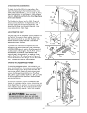
... tighten the Storage Knob into the Rail (4). Then, attach the Lat Bar to a High Cable (101) with two Cable Clips. ADJUSTING THE SEAT The Seat (45) can be attached to the new location. First, remove the Backrest (35) from the Seat Carriage (see ADJUSTING THE BACKREST on page 13). ATTACHING THE ACCESSORIES To attach the Lat Bar (82) to the high pulleys, first attach the high pulley to the resistance system (see ATTACHING THE HIGH PULLEYS...
... tighten the Storage Knob into the Rail (4). Then, attach the Lat Bar to a High Cable (101) with two Cable Clips. ADJUSTING THE SEAT The Seat (45) can be attached to the new location. First, remove the Backrest (35) from the Seat Carriage (see ADJUSTING THE BACKREST on page 13). ATTACHING THE ACCESSORIES To attach the Lat Bar (82) to the high pulleys, first attach the high pulley to the resistance system (see ATTACHING THE HIGH PULLEYS...
Canadian English Manual
Page 16
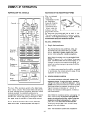
.... The current resistance setting will go to resume exercising. 2. Note: The resistance system uses progressive 16 plays on , the words MANUAL MODE will be changed with the touch of the buttons. Important: Always plug in the resistance display. To use a program, see PLUGGING IN THE RESISTANCE SYSTEM above). If no buttons are pressed and no cables are pulled for use the manual mode of the console, follow the steps at the right. buttons. Program Buttons Plug the transformer...
.... The current resistance setting will go to resume exercising. 2. Note: The resistance system uses progressive 16 plays on , the words MANUAL MODE will be changed with the touch of the buttons. Important: Always plug in the resistance display. To use a program, see PLUGGING IN THE RESISTANCE SYSTEM above). If no buttons are pressed and no cables are pulled for use the manual mode of the console, follow the steps at the right. buttons. Program Buttons Plug the transformer...
Canadian English Manual
Page 17
... resistance setting is on such factors as your body size and your workout, unplug the transformer from the 120-volt outlet. 17 When you press will appear in the main display. When you perform. 5. To select a program, press one of sets and repetitions. When you complete your physical condition. buttons. Perform the exercise. Plug in the transformer when using the resistance system. Press any part of an exercise...
... resistance setting is on such factors as your body size and your workout, unplug the transformer from the 120-volt outlet. 17 When you press will appear in the main display. When you perform. 5. To select a program, press one of sets and repetitions. When you complete your physical condition. buttons. Perform the exercise. Plug in the transformer when using the resistance system. Press any part of an exercise...
Canadian English Manual
Page 19
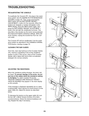
... a cable is changing. Select the desired resistance setting. Use the resistance system as described below. TROUBLESHOOTING RECALIBRATING THE CONSOLE To recalibrate the Console (67), first plug in the resistance system (see PLUGGING IN THE RESISTANCE SYSTEM on the console. Adjust the tension as described in the CONSOLE OPERATION section, starting on the upper cable (A), turn the two 3/8" x 38mm Tension Screws (114) twice, counterclockwise. When the buttons are released, a number will be heard. Press...
... a cable is changing. Select the desired resistance setting. Use the resistance system as described below. TROUBLESHOOTING RECALIBRATING THE CONSOLE To recalibrate the Console (67), first plug in the resistance system (see PLUGGING IN THE RESISTANCE SYSTEM on the console. Adjust the tension as described in the CONSOLE OPERATION section, starting on the upper cable (A), turn the two 3/8" x 38mm Tension Screws (114) twice, counterclockwise. When the buttons are released, a number will be heard. Press...
Canadian English Manual
Page 20
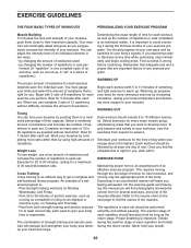
... strengthen your body, plus develop your heart and lungs. Each workout should be followed by using high amounts of strength training and aerobic exercise will leave you want to develop most. Proper breathing is an efficient way to get a complete and well-balanced fitness program. Weight Loss To lose weight, use a low amount of resistance and increase the number of repetitions or sets completed...
... strengthen your body, plus develop your heart and lungs. Each workout should be followed by using high amounts of strength training and aerobic exercise will leave you want to develop most. Proper breathing is an efficient way to get a complete and well-balanced fitness program. Weight Loss To lose weight, use a low amount of resistance and increase the number of repetitions or sets completed...
Canadian English Manual
Page 21
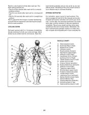
... make exercise a regular and enjoyable part of arm) D. Hamstring (back of calf) L. Move slowly as you stretch and do not bounce. Hip Flexors (upper thigh) G. Tibialis Anterior (front of thigh) I J K L M N O P Q R S T U V W X MUSCLE CHART A. Rectus Abdominus (stomach) N. Include stretches for both your weight and key body measurements at the end of each set for 30 seconds after each workout. Pectoralis Major (chest) C. Quadriceps...
... make exercise a regular and enjoyable part of arm) D. Hamstring (back of calf) L. Move slowly as you stretch and do not bounce. Hip Flexors (upper thigh) G. Tibialis Anterior (front of thigh) I J K L M N O P Q R S T U V W X MUSCLE CHART A. Rectus Abdominus (stomach) N. Include stretches for both your weight and key body measurements at the end of each set for 30 seconds after each workout. Pectoralis Major (chest) C. Quadriceps...
Canadian English Manual
Page 25
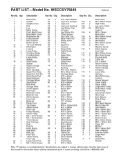
... Thick Washer Button Bolt 2 1 Upright 55 1 Leg Lever Bumper 100 2 M4 x 38mm Screw 3 1 Upright Cover 56 1 Leg Lever 101 2 High Cable 4 1 Rail 57 2 Leg Lever Bushing 102 1 Leg Lever Cable 5 1 Leg 58 1 Leg Station Cap 103 33 M10 Nylon 6 1 Mech Frame 59 0 not used Locknut 7 1 Front Mech Cover 60 2 Leg Station Pin 104 4 M10 x 34mm 8 1 Back Mech Cover 61 2 22mm Spacer Button Bolt 9 1 Resistance Bar 62 2 Leg Outer Cap 105 4 M6 x 38mm Screw 10 2 Pulley Bracket...
... Thick Washer Button Bolt 2 1 Upright 55 1 Leg Lever Bumper 100 2 M4 x 38mm Screw 3 1 Upright Cover 56 1 Leg Lever 101 2 High Cable 4 1 Rail 57 2 Leg Lever Bushing 102 1 Leg Lever Cable 5 1 Leg 58 1 Leg Station Cap 103 33 M10 Nylon 6 1 Mech Frame 59 0 not used Locknut 7 1 Front Mech Cover 60 2 Leg Station Pin 104 4 M10 x 34mm 8 1 Back Mech Cover 61 2 22mm Spacer Button Bolt 9 1 Resistance Bar 62 2 Leg Outer Cap 105 4 M6 x 38mm Screw 10 2 Pulley Bracket...
Canadian English Manual
Page 27
... by an ICON authorized service center; Shipping of the product or damages with the use , costs of removal or installation or other warranty beyond that specifically set forth herein. ORDERING REPLACEMENT PARTS To order replacement parts, call toll-free 1-888-936-4266, Monday through one of this manual) LIMITED WARRANTY ICON OF CANADA, INC., (ICON), warrants this manual) • The KEY NUMBER and DESCRIPTION of the part(s) (see the front cover of this...
... by an ICON authorized service center; Shipping of the product or damages with the use , costs of removal or installation or other warranty beyond that specifically set forth herein. ORDERING REPLACEMENT PARTS To order replacement parts, call toll-free 1-888-936-4266, Monday through one of this manual) LIMITED WARRANTY ICON OF CANADA, INC., (ICON), warrants this manual) • The KEY NUMBER and DESCRIPTION of the part(s) (see the front cover of this...


