
English Manual
Page 15
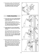
...Cable to identify the cables and ensure proper cable routing. During steps 25-52, see the CABLE DIAGRAM on page 28 to the Right Upright (7) with an M10 x 50mm Bolt (105) and an M10 Nylon Locknut (84). Wrap the Butterfly Cable (73) around a Pulley 26 (43). Make sure that the Cable Trap is oriented to hold the Cable...an M8 x 25mm Shoulder Bolt (92) and an M8 Nylon Locknut (101). Make sure that the Cable Trap is oriented to hold the Cable in the groove of pulleys. Wrap the Butterfly Cable (73) around a Pulley (43). Attach 23 the Leg Press Plate (29) to the Right ...
...Cable to identify the cables and ensure proper cable routing. During steps 25-52, see the CABLE DIAGRAM on page 28 to the Right Upright (7) with an M10 x 50mm Bolt (105) and an M10 Nylon Locknut (84). Wrap the Butterfly Cable (73) around a Pulley 26 (43). Make sure that the Cable Trap is oriented to hold the Cable...an M8 x 25mm Shoulder Bolt (92) and an M8 Nylon Locknut (101). Make sure that the Cable Trap is oriented to hold the Cable in the groove of pulleys. Wrap the Butterfly Cable (73) around a Pulley (43). Attach 23 the Leg Press Plate (29) to the Right ...
English Manual
Page 17
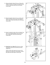
... 45mm Bolt (95) and an M10 Nylon Locknut (84). 84 3 73 95 43 32. 31. Wrap the Butterfly Cable (73) over a Pulley (43). 32 Attach the Pulley to the Right Top Frame (3) with an M10 x 50mm ...Bolt (105) and an M10 Nylon Locknut (84). 73 84 67 75 105 34. Route the Cable 34 through the Leg Lever (15) and the Curl Post Upright (10). Attach a Pulley (43) inside ... Bolt (95) and an M10 Nylon Locknut (84). 43 84 73 95 6 33. Identify the Low Cable (70). Wrap the Butterfly Cable (73) over a Pulley (43). 31 Attach the Pulley to the Center Top Frame (6) with an M10...
... 45mm Bolt (95) and an M10 Nylon Locknut (84). 84 3 73 95 43 32. 31. Wrap the Butterfly Cable (73) over a Pulley (43). 32 Attach the Pulley to the Right Top Frame (3) with an M10 x 50mm ...Bolt (105) and an M10 Nylon Locknut (84). 73 84 67 75 105 34. Route the Cable 34 through the Leg Lever (15) and the Curl Post Upright (10). Attach a Pulley (43) inside ... Bolt (95) and an M10 Nylon Locknut (84). 43 84 73 95 6 33. Identify the Low Cable (70). Wrap the Butterfly Cable (73) over a Pulley (43). 31 Attach the Pulley to the Center Top Frame (6) with an M10...
English Manual
Page 18
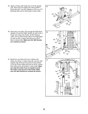
...shown. 37. Attach the Pulley, an M10 Washer (108), and two Half Guards (46) to hold the Cable in the groove of the two Pulley Plates (49) with an M10 x 50mm Bolt (105) and an...18 Wrap the Low Cable (70) over a Pulley (43). 37 Attach the Pulley, a Cable Trap (48), and two Half Guards (46) at the second hole from the bottom of the Pulley. Route the Low Cable (70) through ...the Right Seat 36 Upright (11) and the Right Upright (7) and under a Pulley (43). Make sure that the Cable Trap is oriented to the Right Base ...
...shown. 37. Attach the Pulley, an M10 Washer (108), and two Half Guards (46) to hold the Cable in the groove of the two Pulley Plates (49) with an M10 x 50mm Bolt (105) and an...18 Wrap the Low Cable (70) over a Pulley (43). 37 Attach the Pulley, a Cable Trap (48), and two Half Guards (46) at the second hole from the bottom of the Pulley. Route the Low Cable (70) through ...the Right Seat 36 Upright (11) and the Right Upright (7) and under a Pulley (43). Make sure that the Cable Trap is oriented to the Right Base ...
English Manual
Page 19
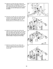
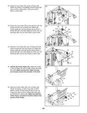
... Right Base (1) with an M10 x 50mm Bolt (105) and an M10 Nylon Locknut (84). Wrap the Low Cable (70) under a Pulley (43). 38 Attach the Pulley, an M10 Washer (108), and two Half Guards (... Plate (50) with an M10 x 45mm Bolt (95) and an M10 Nylon Locknut (84). Wrap the Low Cable (70) over a Pulley (43) and 39 through the Center Upright (9). Attach the Pulley inside the Center Upright...43 108 1 39. 38. Route the Low Cable (70) over a Pulley (43). 41 Attach the Pulley to hold the Cable in the groove of the Pulley. 41. Make sure that the Cable Trap is oriented to the Left...
... Right Base (1) with an M10 x 50mm Bolt (105) and an M10 Nylon Locknut (84). Wrap the Low Cable (70) under a Pulley (43). 38 Attach the Pulley, an M10 Washer (108), and two Half Guards (... Plate (50) with an M10 x 45mm Bolt (95) and an M10 Nylon Locknut (84). Wrap the Low Cable (70) over a Pulley (43) and 39 through the Center Upright (9). Attach the Pulley inside the Center Upright...43 108 1 39. 38. Route the Low Cable (70) over a Pulley (43). 41 Attach the Pulley to hold the Cable in the groove of the Pulley. 41. Make sure that the Cable Trap is oriented to the Left...
English Manual
Page 20
Route the Low Cable (70) up through the Left Top Frame (4). Wrap the Low Cable (70) under a Pulley (43). 42 Attach the Pulley to hold the Cable in the groove of the Bolt. 46. 42. Make sure that the Cable Trap is oriented to the Military Press Frame (20) with an M10 x 120mm Bolt (97) and... an M10 Nylon Locknut (84). Make sure that the Cable end can pivot easily around the shoulder of the Pulley. 20 43 4 84 68 68 108 87 108 70 92 2 72 72 97 45 48 ...
Route the Low Cable (70) up through the Left Top Frame (4). Wrap the Low Cable (70) under a Pulley (43). 42 Attach the Pulley to hold the Cable in the groove of the Bolt. 46. 42. Make sure that the Cable Trap is oriented to the Military Press Frame (20) with an M10 x 120mm Bolt (97) and... an M10 Nylon Locknut (84). Make sure that the Cable end can pivot easily around the shoulder of the Pulley. 20 43 4 84 68 68 108 87 108 70 92 2 72 72 97 45 48 ...
English Manual
Page 24
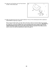
... over the pulleys. IMPORTANT: If the cables are not properly installed, they may be explained in the cables, you will be damaged when heavy weight is any slack in ADJUSTMENTS, beginning on page 28 for proper cable routing. Make sure that the cables move smoothly, find and correct the problem.... See the CABLE DIAGRAM on page 25. Attach the Curl Pad (38) to make sure that all parts have...
... over the pulleys. IMPORTANT: If the cables are not properly installed, they may be explained in the cables, you will be damaged when heavy weight is any slack in ADJUSTMENTS, beginning on page 28 for proper cable routing. Make sure that the cables move smoothly, find and correct the problem.... See the CABLE DIAGRAM on page 25. Attach the Curl Pad (38) to make sure that all parts have...
English Manual
Page 28
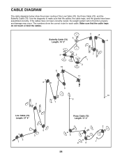
... not function properly and damage may occur. CABLE DIAGRAM The cable diagrams below show the correct route for each cable. Use the diagrams to make sure that the cable traps do not touch or bind the cables. 5 Butterfly Cable (73) Length: 10' 2" 6 8 9 4 10 8 3 7 1 2 11 6 9 10 6 7 4 Low Cable (70) Length: 27' 8" 2 1 5 3 Press Cable (72) Length: 11' 2" 2 4 5 1 3 28 The numbers show...
... not function properly and damage may occur. CABLE DIAGRAM The cable diagrams below show the correct route for each cable. Use the diagrams to make sure that the cable traps do not touch or bind the cables. 5 Butterfly Cable (73) Length: 10' 2" 6 8 9 4 10 8 3 7 1 2 11 6 9 10 6 7 4 Low Cable (70) Length: 27' 8" 2 1 5 3 Press Cable (72) Length: 11' 2" 2 4 5 1 3 28 The numbers show...


