
English Manual
Page 2
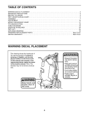
... decal(s). Note: The decal(s) may not be shown at actual size. TABLE OF CONTENTS WARNING DECAL PLACEMENT 2 IMPORTANT PRECAUTIONS 3 BEFORE YOU BEGIN 4 PART IDENTIFICATION CHART 5 ASSEMBLY 7 ADJUSTMENT 15 WEIGHT RESISTANCE CHART 17 TROUBLESHOOTING 18 CABLE DIAGRAMS 19 EXERCISE GUIDELINES 20 PART LIST 22 EXPLODED DRAWING 23 ORDERING REPLACEMENT PARTS Back Cover...
... decal(s). Note: The decal(s) may not be shown at actual size. TABLE OF CONTENTS WARNING DECAL PLACEMENT 2 IMPORTANT PRECAUTIONS 3 BEFORE YOU BEGIN 4 PART IDENTIFICATION CHART 5 ASSEMBLY 7 ADJUSTMENT 15 WEIGHT RESISTANCE CHART 17 TROUBLESHOOTING 18 CABLE DIAGRAMS 19 EXERCISE GUIDELINES 20 PART LIST 22 EXPLODED DRAWING 23 ORDERING REPLACEMENT PARTS Back Cover...
English Manual
Page 4
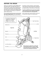
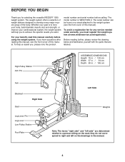
...needed under warranty, you must register the weight system at www.weiderservice.com/registration. To avoid a registration fee for selecting the versatile WEIDER PRO™ 2250 weight system. For your cardiovascular system, the weight system will help us assist you, note the product model number... serial number before Before reading further, please familiarize yourself with you use the weight system. To help you to develop every major muscle group of ASSEMBLED DIMENSIONS: Height: 6 ft. 4 in. (193 cm) Width: 3 ft. 2 in. (97 cm) Length: 4 ft. 5 in the drawing below. after reading ...
...needed under warranty, you must register the weight system at www.weiderservice.com/registration. To avoid a registration fee for selecting the versatile WEIDER PRO™ 2250 weight system. For your cardiovascular system, the weight system will help us assist you, note the product model number... serial number before Before reading further, please familiarize yourself with you use the weight system. To help you to develop every major muscle group of ASSEMBLED DIMENSIONS: Height: 6 ft. 4 in. (193 cm) Width: 3 ft. 2 in. (97 cm) Length: 4 ft. 5 in the drawing below. after reading ...
English Manual
Page 5
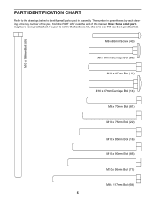
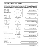
... the end of this manual. The number in parentheses by each drawing is not in the hardware kit, check to identify small parts used in assembly. Note: Some small parts may have been preattached.
... the end of this manual. The number in parentheses by each drawing is not in the hardware kit, check to identify small parts used in assembly. Note: Some small parts may have been preattached.
English Manual
Page 7
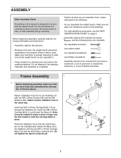
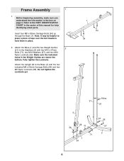
...M10 x 67mm Carriage Bolts (14) and two M10 Nylon Locknuts (21). Attach a Stabilizer Foot (51) to walk around the weight bench as you assemble it will go smoothly. Insert two M10 x 67mm Carriage Bolts (14) up through the Stabilizer (5). Orient the Stabilizer (5) so that you have read... information in the box above. Do not tighten the Nylon Locknuts yet. 21 4 1 51 Small Holes 14 5 51 82 56 7 Frame Assembly 1 1. ASSEMBLY Make Assembly Easier Everything in this manual is designed to the Stabilizer with two M4 x 20mm Screws (56) and two M4 Washers (82). Attach another ...
...M10 x 67mm Carriage Bolts (14) and two M10 Nylon Locknuts (21). Attach a Stabilizer Foot (51) to walk around the weight bench as you assemble it will go smoothly. Insert two M10 x 67mm Carriage Bolts (14) up through the Stabilizer (5). Orient the Stabilizer (5) so that you have read... information in the box above. Do not tighten the Nylon Locknuts yet. 21 4 1 51 Small Holes 14 5 51 82 56 7 Frame Assembly 1 1. ASSEMBLY Make Assembly Easier Everything in this manual is designed to the Stabilizer with two M4 x 20mm Screws (56) and two M4 Washers (82). Attach another ...
English Manual
Page 9
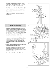
The Plastic Bushings should fit onto each end of the indicated holes. Assemble the Left Press Arm (73) in the indicated position. Note: This will be a tight fit. Attach the Press Frame (17) to the Base (4) with grease. ...Identify the Right and Left Press Arms (46, 73) by the position of the indicated tube in steps 2 and 4. 9 3 9 60 42 62 Arm Assembly 5. Slide the Press Frame into place on the Press Frame (17). the Press Frame must pivot easily. 6. Lubricate an M10 x 198mm Bolt (59) with the...
The Plastic Bushings should fit onto each end of the indicated holes. Assemble the Left Press Arm (73) in the indicated position. Note: This will be a tight fit. Attach the Press Frame (17) to the Base (4) with grease. ...Identify the Right and Left Press Arms (46, 73) by the position of the indicated tube in steps 2 and 4. 9 3 9 60 42 62 Arm Assembly 5. Slide the Press Frame into place on the Press Frame (17). the Press Frame must pivot easily. 6. Lubricate an M10 x 198mm Bolt (59) with the...
English Manual
Page 10
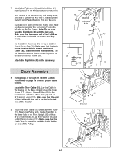
...). 7. Make sure that the Cable Trap is in the same way. 7 55 55 48 Bracket Lubricate Axle 69 70 69 70 74 47 45 Cable Assembly 8 8.
...). 7. Make sure that the Cable Trap is in the same way. 7 55 55 48 Bracket Lubricate Axle 69 70 69 70 74 47 45 Cable Assembly 8 8.
English Manual
Page 13
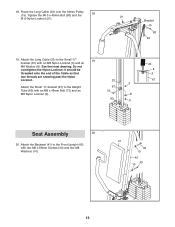
.... Attach the Backrest (41) to the Front Upright (42) with an M8 x 45mm Bolt (72) and an 72 M8 Nylon Locknut (3). 8 63 3 23 8 3 67 Seat Assembly 20 20. Route the Long Cable (23) over the 90mm Pulley (15). Do not overtighten the Nylon Locknut; 18.
.... Attach the Backrest (41) to the Front Upright (42) with an M8 x 45mm Bolt (72) and an 72 M8 Nylon Locknut (3). 8 63 3 23 8 3 67 Seat Assembly 20 20. Route the Long Cable (23) over the 90mm Pulley (15). Do not overtighten the Nylon Locknut; 18.

English Manual
Page 14
... direction shown. Then, 30 slide two Small Pads (30) onto the Pad Tube. Attach the Eyebolt with an M6 Washer (10) onto the Carriage Bolt. Assemble the other end of the Seat (13) to the Seat Frame (36) with soapy water. Insert an Eyebolt (35) into the Seat Frame (36). 23...
... direction shown. Then, 30 slide two Small Pads (30) onto the Pad Tube. Attach the Eyebolt with an M6 Washer (10) onto the Carriage Bolt. Assemble the other end of the Seat (13) to the Seat Frame (36) with soapy water. Insert an Eyebolt (35) into the Seat Frame (36). 23...

English Manual
Page 19
The numbers show the proper routing of the Long Cable (23) and the Short Cable (58). Make sure that the two cables and the cable traps have not been correctly routed, the weight system will not function properly and damage may occur. If the cables have been assembled correctly. Use the diagram to make sure that the cable traps do not touch or bind the cables. 5 7 4 1 2 3 Long Cable (23) 6 5 8 Short Cable (58) 4 3 2 1 19 CABLE DIAGRAMS The cable diagrams show the correct route for each cable.
The numbers show the proper routing of the Long Cable (23) and the Short Cable (58). Make sure that the two cables and the cable traps have not been correctly routed, the weight system will not function properly and damage may occur. If the cables have been assembled correctly. Use the diagram to make sure that the cable traps do not touch or bind the cables. 5 7 4 1 2 3 Long Cable (23) 6 5 8 Short Cable (58) 4 3 2 1 19 CABLE DIAGRAMS The cable diagrams show the correct route for each cable.
User Manual
Page 2
...both sides of the upright Decal 2 Decal 2 WEIDER is missing or illegible, please call the toll-free telephone number on the weight system. Remove the PART IDENTIFICATION CHART and PART LIST/EXPLODED DRAWING before beginning assembly. If a decal is a registered trademark of... the decal in the center of this manual. TABLE OF CONTENTS WARNING DECAL PLACEMENT 2 IMPORTANT PRECAUTIONS 3 BEFORE YOU BEGIN 4 ASSEMBLY 5 ADJUSTMENTS 16 WEIGHT RESISTANCE CHART 18 CABLE DIAGRAMS 19 MAINTENANCE 20 EXERCISE GUIDELINES 21 ORDERING REPLACEMENT PARTS Back Cover LIMITED WARRANTY Back...
...both sides of the upright Decal 2 Decal 2 WEIDER is missing or illegible, please call the toll-free telephone number on the weight system. Remove the PART IDENTIFICATION CHART and PART LIST/EXPLODED DRAWING before beginning assembly. If a decal is a registered trademark of... the decal in the center of this manual. TABLE OF CONTENTS WARNING DECAL PLACEMENT 2 IMPORTANT PRECAUTIONS 3 BEFORE YOU BEGIN 4 ASSEMBLY 5 ADJUSTMENTS 16 WEIGHT RESISTANCE CHART 18 CABLE DIAGRAMS 19 MAINTENANCE 20 EXERCISE GUIDELINES 21 ORDERING REPLACEMENT PARTS Back Cover LIMITED WARRANTY Back...
User Manual
Page 4
... be found on a decal attached to develop every major muscle group of this manual. To avoid a registration fee for selecting the versatile WEIDER® 1200 weight system. BEFORE YOU BEGIN Thank you for any service needed under warranty, you must register the weight system at www.weiderservice.com/registration... the drawing below and familiarize yourself with the parts that are determined relative to right and left on the seat; High Pulley Station Arm Pin ASSEMBLED DIMENSIONS: Height: 76 in. / 193 cm Width: 37 in. / 94 cm Depth: 65 in the manual. 4 they do not correspond to a ...
... be found on a decal attached to develop every major muscle group of this manual. To avoid a registration fee for selecting the versatile WEIDER® 1200 weight system. BEFORE YOU BEGIN Thank you for any service needed under warranty, you must register the weight system at www.weiderservice.com/registration... the drawing below and familiarize yourself with the parts that are determined relative to right and left on the seat; High Pulley Station Arm Pin ASSEMBLED DIMENSIONS: Height: 76 in. / 193 cm Width: 37 in. / 94 cm Depth: 65 in the manual. 4 they do not correspond to a ...

User Manual
Page 5
... If a part is completed. How to Orient Parts As you begin by almost anyone. Important: Wait until assembly is not in the drawings. Questions? ASSEMBLY Make Assembly Easier for that stage. By deciding to make sure to do otherwise. How to Identify Parts Refer to the... attach the cables and pulleys that form the skeleton of its weight and size, the weight system should be assembled in assembly. Note: Assembly may be required for assembly: • Two adjustable wrenches • One standard screwdriver Hire an Authorized Service Technician To hire an authorized ...
... If a part is completed. How to Orient Parts As you begin by almost anyone. Important: Wait until assembly is not in the drawings. Questions? ASSEMBLY Make Assembly Easier for that stage. By deciding to make sure to do otherwise. How to Identify Parts Refer to the... attach the cables and pulleys that form the skeleton of its weight and size, the weight system should be assembled in assembly. Note: Assembly may be required for assembly: • Two adjustable wrenches • One standard screwdriver Hire an Authorized Service Technician To hire an authorized ...
User Manual
Page 6
Frame Assembly 1 1. Refer to the PART IDENTIFICATION CHART in place. 2. Make sure the indicated holes in the box on page 5. Fully tighten the Locknuts. Insert four M8 x ... Locknuts (56). Attach the Upright (3) to the Stabilizer (2) with the two indicated M8 x 63mm Carriage Bolts (64) and two M8 Nylon Locknuts (58). Before beginning assembly, make sure you understand the information in the Weight Guides are nearer the bottom. Do not tighten the Locknuts yet. 1 64 64 Holes 21 21...
Frame Assembly 1 1. Refer to the PART IDENTIFICATION CHART in place. 2. Make sure the indicated holes in the box on page 5. Fully tighten the Locknuts. Insert four M8 x ... Locknuts (56). Attach the Upright (3) to the Stabilizer (2) with the two indicated M8 x 63mm Carriage Bolts (64) and two M8 Nylon Locknuts (58). Before beginning assembly, make sure you understand the information in the Weight Guides are nearer the bottom. Do not tighten the Locknuts yet. 1 64 64 Holes 21 21...

User Manual
Page 8
... the Arm Pins into the two holes in steps 2-6. 68 59 76 59 4 56 57 76 57 74 Welded Support 58 58 3 21 21 Arm Assembly 7. Attach the 8 Pivot Frame (5) to the Pivot Frame (5) with the Bolt and an M10 Nylon Locknut (56). Attach the two Arm Pins (40) to the...
... the Arm Pins into the two holes in steps 2-6. 68 59 76 59 4 56 57 76 57 74 Welded Support 58 58 3 21 21 Arm Assembly 7. Attach the 8 Pivot Frame (5) to the Pivot Frame (5) with the Bolt and an M10 Nylon Locknut (56). Attach the two Arm Pins (40) to the...

User Manual
Page 9
...Locate the Arm Cable (54). Make sure that the cable end can pivot easily on page 19 as you assemble the cables and to the Left Arm (10) with the Bolt, two M10 Washers (57), the two ... M10 Nylon Locknut (56). Grease an M10 x 51mm Bolt (66). Attach a Handle (11) to identify the cables. Assemble the Right Arm (9) in the same manner. 9 66 Grease 39 56 10 42 11 57 77 57 Grease 9 44 ...67 5 44 57 Grease 57 56 10 Cable Assembly 11 11. Do not overtighten the Locknut; Grease an M10 x 85mm Bolt (67) and two Arm 10 Bushings ...
...Locate the Arm Cable (54). Make sure that the cable end can pivot easily on page 19 as you assemble the cables and to the Left Arm (10) with the Bolt, two M10 Washers (57), the two ... M10 Nylon Locknut (56). Grease an M10 x 51mm Bolt (66). Attach a Handle (11) to identify the cables. Assemble the Right Arm (9) in the same manner. 9 66 Grease 39 56 10 42 11 57 77 57 Grease 9 44 ...67 5 44 57 Grease 57 56 10 Cable Assembly 11 11. Do not overtighten the Locknut; Grease an M10 x 85mm Bolt (67) and two Arm 10 Bushings ...

User Manual
Page 14
... 72 73 7 29 28 28 28 8 28 14 Attach the Seat (15) to the Front Leg (7) with an M4 x 20mm Self-tapping Screw (69). Seat Assembly 28 28. Insert the Leg Lever Pin through the Front Leg (7). Do not overtighten the Locknut; Attach the Lock Plate (73) to the Seat Frame...
... 72 73 7 29 28 28 28 8 28 14 Attach the Seat (15) to the Front Leg (7) with an M4 x 20mm Self-tapping Screw (69). Seat Assembly 28 28. Insert the Leg Lever Pin through the Front Leg (7). Do not overtighten the Locknut; Attach the Lock Plate (73) to the Seat Frame...

User Manual
Page 19
... traps, and finger guards have not been correctly routed, the weight system will not function properly and damage may occur. If the cables have been assembled correctly.
... traps, and finger guards have not been correctly routed, the weight system will not function properly and damage may occur. If the cables have been assembled correctly.
User Manual
Page 24
... each drawing is not in the center of the part, from the PART LIST in the parts bag, check to identify small parts used in assembly. If a part is the key number of this manual. M8 Nylon Locknut (58) M10 Nylon Locknut (56) Large Washer (78) M12 Nut (82) M10 Washer...
... each drawing is not in the center of the part, from the PART LIST in the parts bag, check to identify small parts used in assembly. If a part is the key number of this manual. M8 Nylon Locknut (58) M10 Nylon Locknut (56) Large Washer (78) M12 Nut (82) M10 Washer...


