Service Manual
Page 4
... Electric Appliance Control IMPORTANT NOTICE CONCERNING POWER CORD SELECTION The power cord set which sit on a desk or table, type SVT or SJT cord sets may be selected according to the country of the inner conductors. The cord set is certified for use by experienced professional technicians. Do Not Copy VX500-1 CAUTION: Use a power cable that is not enclosed. 1. Any attempt to service or repair the product...
... Electric Appliance Control IMPORTANT NOTICE CONCERNING POWER CORD SELECTION The power cord set which sit on a desk or table, type SVT or SJT cord sets may be selected according to the country of the inner conductors. The cord set is certified for use by experienced professional technicians. Do Not Copy VX500-1 CAUTION: Use a power cable that is not enclosed. 1. Any attempt to service or repair the product...
Service Manual
Page 5
... colored BROWN must be connected to continue using the ViewPanel. PRECAUTION ■ For best viewing conditions sit at least 18" from the skin are colored in accordance with care when moving it. ■ Place your dealer or ViewSonic. You may suffer serious injury if you have purchased the product. Do not place anything on the ViewPanel, video cable, or power cord...
... colored BROWN must be connected to continue using the ViewPanel. PRECAUTION ■ For best viewing conditions sit at least 18" from the skin are colored in accordance with care when moving it. ■ Place your dealer or ViewSonic. You may suffer serious injury if you have purchased the product. Do not place anything on the ViewPanel, video cable, or power cord...
Service Manual
Page 6
... local distributor or repair center. FEATURE The purpose of a detailed I/O connector PIN ASSIGNMENT for the LCD Monitor. The manual includes Engineering Specification, Front Panel Control description, Circuit Description, Troubleshooting, Theory of this section are complex or aren't mentioned in procuring replacement parts for this manual is written and designed for detailed product specification. CIRCUIT DESCRIPTIONS The first part of Operation, Mechanical Assembly, Service Parts List, and Circuit...
... local distributor or repair center. FEATURE The purpose of a detailed I/O connector PIN ASSIGNMENT for the LCD Monitor. The manual includes Engineering Specification, Front Panel Control description, Circuit Description, Troubleshooting, Theory of this section are complex or aren't mentioned in procuring replacement parts for this manual is written and designed for detailed product specification. CIRCUIT DESCRIPTIONS The first part of Operation, Mechanical Assembly, Service Parts List, and Circuit...
Service Manual
Page 7
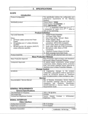
... Power Cable, "Schuko". Analog VGA Cable. connectors. Audio cable. VX500 unit with PC99. Service Documentation / Service Manual Bills of Material, Schematics, Service Manual, and Assembly Drawings shall be approved in compliance with PC99 Connectors. 8. GENERAL REQUIREMENTS General Specifications Test Resolution & Frequency 1024 x 768 @ 60Hz Test Image Size Full Size Contrast and Brightness Controls Factory Default: Contrast = 50%(center), Brightness = 100% SIGNAL INTERFACE Video Interface Analog Input Connector DB-15 (Analog) Digital Input Connector DVI-D (Digital...
... Power Cable, "Schuko". Analog VGA Cable. connectors. Audio cable. VX500 unit with PC99. Service Documentation / Service Manual Bills of Material, Schematics, Service Manual, and Assembly Drawings shall be approved in compliance with PC99 Connectors. 8. GENERAL REQUIREMENTS General Specifications Test Resolution & Frequency 1024 x 768 @ 60Hz Test Image Size Full Size Contrast and Brightness Controls Factory Default: Contrast = 50%(center), Brightness = 100% SIGNAL INTERFACE Video Interface Analog Input Connector DB-15 (Analog) Digital Input Connector DVI-D (Digital...
Service Manual
Page 8
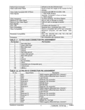
... after market video cards. 640 x 350, 640x400, 640 x 480, 720 x 400, 800 x 600, and 1024 x 768 Not compatible with interlaced video. Video RGB (Analog) Separate, Composite, or Sync on Green 2. TABLE 3.1: 15 PIN D-SUB CONNECTOR PIN ASSIGNMENT Pin Number 1 2 3 4 5 6 7 8 9 10 11 12 13 14 15 Pin Function Red video input Green video input Blue video input Ground Ground Red video ground Green video ground Blue video ground +5V Ground No connection (SDA) Horizontal sync (Composite sync) Vertical sync (SCL) TABLE 3.2: 24 PIN DVI-D CONNECTOR PIN ASSIGNMENT...
... after market video cards. 640 x 350, 640x400, 640 x 480, 720 x 400, 800 x 600, and 1024 x 768 Not compatible with interlaced video. Video RGB (Analog) Separate, Composite, or Sync on Green 2. TABLE 3.1: 15 PIN D-SUB CONNECTOR PIN ASSIGNMENT Pin Number 1 2 3 4 5 6 7 8 9 10 11 12 13 14 15 Pin Function Red video input Green video input Blue video input Ground Ground Red video ground Green video ground Blue video ground +5V Ground No connection (SDA) Horizontal sync (Composite sync) Vertical sync (SCL) TABLE 3.2: 24 PIN DVI-D CONNECTOR PIN ASSIGNMENT...
Service Manual
Page 9
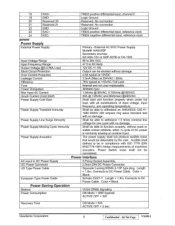
...- Model#: HASU05F Secondary sources: SA140A-12V or ADP-40TB or CH-1204 Input Voltage Range 90 to 264 VAC Input Frequency Range 47.5 to DC Power Cable. Power Supply Acoustics The power supply shall not produce audible noise that would be shorted without reset or visible screen artifacts, when 'A cycle of input voltage, input frequency, and operating temperature. European Type Power Cable Schuko CEE7-7. Color = Black Power Saving Operation Method VESA DPMS Signaling Power Consumption ON Mode < 36W...
...- Model#: HASU05F Secondary sources: SA140A-12V or ADP-40TB or CH-1204 Input Voltage Range 90 to 264 VAC Input Frequency Range 47.5 to DC Power Cable. Power Supply Acoustics The power supply shall not produce audible noise that would be shorted without reset or visible screen artifacts, when 'A cycle of input voltage, input frequency, and operating temperature. European Type Power Cable Schuko CEE7-7. Color = Black Power Saving Operation Method VESA DPMS Signaling Power Consumption ON Mode < 36W...
Service Manual
Page 10
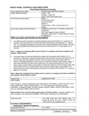
... Button 2 Audio buttons: Mute, volume down ", "up Power Short Cuts Function from the button(s) [DOWN] or [UP] arrow = to access the OSD by pressing the front panel control buttons "(1), & (down )" again for 10 seconds. Note 1: Status bar indicating OSD Lock or Unlock is in the locked mode, then power should return to factory setting: Contrast, brightness, h/v size, h position, color temperature @ 6500K, OSD position, sharpness, and OSD timeout. OSD Auto Save ELECTRICAL REQUIREMENTS Horizontal / Vertical Frequency Horizontal Frequency ViewSonic Corporation The OSD shall save...
... Button 2 Audio buttons: Mute, volume down ", "up Power Short Cuts Function from the button(s) [DOWN] or [UP] arrow = to access the OSD by pressing the front panel control buttons "(1), & (down )" again for 10 seconds. Note 1: Status bar indicating OSD Lock or Unlock is in the locked mode, then power should return to factory setting: Contrast, brightness, h/v size, h position, color temperature @ 6500K, OSD position, sharpness, and OSD timeout. OSD Auto Save ELECTRICAL REQUIREMENTS Horizontal / Vertical Frequency Horizontal Frequency ViewSonic Corporation The OSD shall save...
Service Manual
Page 11
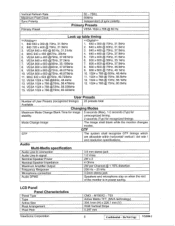
... 8. MAC 832 x 624 @75Hz, 49.725kHz 12. LCD Panel Panel Characteristics Panel Type Type Active Size Pixel Arrangement Pixel Pitch ViewSonic Corporation CMO - VESA 640 x 480 @ 60 Hz, 31.5 kHz 4. VESA 1024 x 768 @60Hz, 48.4kHz 13. VESA 1024 x 768 @72Hz, 58.036kHz 15. Audio Multi-Media specification Audio Line-In connection 3.5 mm stereo jack Audio Line-In signal Nominal Speaker Power 1.0 Vrms 2W x 2 Nominal Speaker Impedance Maximum Amplifier Output Frequency Response Microphone connection Audio...
... 8. MAC 832 x 624 @75Hz, 49.725kHz 12. LCD Panel Panel Characteristics Panel Type Type Active Size Pixel Arrangement Pixel Pitch ViewSonic Corporation CMO - VESA 640 x 480 @ 60 Hz, 31.5 kHz 4. VESA 1024 x 768 @60Hz, 48.4kHz 13. VESA 1024 x 768 @72Hz, 58.036kHz 15. Audio Multi-Media specification Audio Line-In connection 3.5 mm stereo jack Audio Line-In signal Nominal Speaker Power 1.0 Vrms 2W x 2 Nominal Speaker Impedance Maximum Amplifier Output Frequency Response Microphone connection Audio...
Service Manual
Page 12
.... Do Not Copy VX500-1 Red, Green, and Blue shall be adjustable. IMAGE PERFORMANCE Factory Defaults Preset Color 6500K (Primary) Contrast Control 50% Brightness Control 100% Disp ay Size Horizontal Display Size, Primary Preset Full Screen Vertical Display Size, Primary Preset Full Screen Frame Refresh Rate Frame Frequency Scan rate conversion shall be performed to match input signal frame rates to best condition. ViewSonic Corporation 9 Confidential - Glass Treatment Anti Glare (Hard coating 3H) # of the monitor Temperature Drift Image shall not drift or...
.... Do Not Copy VX500-1 Red, Green, and Blue shall be adjustable. IMAGE PERFORMANCE Factory Defaults Preset Color 6500K (Primary) Contrast Control 50% Brightness Control 100% Disp ay Size Horizontal Display Size, Primary Preset Full Screen Vertical Display Size, Primary Preset Full Screen Frame Refresh Rate Frame Frequency Scan rate conversion shall be performed to match input signal frame rates to best condition. ViewSonic Corporation 9 Confidential - Glass Treatment Anti Glare (Hard coating 3H) # of the monitor Temperature Drift Image shall not drift or...
Service Manual
Page 13
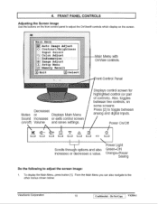
... CD I_ I Scrolls through options and also increases or decreases a value. To display the Main Menu, press button [1]. Power Light Green=0N Orange.Power Saving Do the following to toggle between two controls, on /off) Volume and saves settings. Do Not Copy VX500-1 Main Menti Auto Image Adjust Contrast/Brightness Input Select Color Adjust Information Image Adjust Setup Menu Memory Recall Ex it 2e t Main Menu with On controls. Press [2] to adjust the screen image: 1. 4. Displays control screen for highlighted control (or pair of...
... CD I_ I Scrolls through options and also increases or decreases a value. To display the Main Menu, press button [1]. Power Light Green=0N Orange.Power Saving Do the following to toggle between two controls, on /off) Volume and saves settings. Do Not Copy VX500-1 Main Menti Auto Image Adjust Contrast/Brightness Input Select Color Adjust Information Image Adjust Setup Menu Memory Recall Ex it 2e t Main Menu with On controls. Press [2] to adjust the screen image: 1. 4. Displays control screen for highlighted control (or pair of...
Service Manual
Page 14
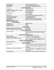
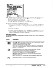
... Auto Image Adjust automatically sizes, centers, auto-contrasts and fine-tunes the video signal to toggle between analog and digital inputs. To adjust the control, press the up or down ♦ buttons. 5. Press button [2] to eliminate waviness and distortion. Color Adjust displays the Color Adjust Menu explained below can be adjusted by using the up A and downy buttons on your graphic card's user guide.) • Select Auto Image Adjust • If necessary, make small adjustments using H POSITION and V POSITION until the screen image is selected, press button [2]. 4. ViewSonic...
... Auto Image Adjust automatically sizes, centers, auto-contrasts and fine-tunes the video signal to toggle between analog and digital inputs. To adjust the control, press the up or down ♦ buttons. 5. Press button [2] to eliminate waviness and distortion. Color Adjust displays the Color Adjust Menu explained below can be adjusted by using the up A and downy buttons on your graphic card's user guide.) • Select Auto Image Adjust • If necessary, make small adjustments using H POSITION and V POSITION until the screen image is selected, press button [2]. 4. ViewSonic...
Service Manual
Page 15
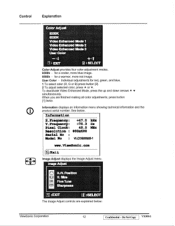
... Video Enhanced Mode 2 Video Entailment Mode 3 User Color :4 Exrr 2 ;SELECT Color Adjust provides four color adjustment modes. 9300k - See below : ViewSonic Corporation 12 Confidential - for red, green, and blue. 1 To select color (R, G or B) press button [2]. 2 To adjust selected color, press A or v. User Color - Infocnnation Barrequirmay: +47.0 kHz ILFrequancy: +73.3 He Pixel Clock: 42.5 MEz Resolution : 800x600 Serial No Nodal No : VLODSN$25-1 vww.litewBonic.com :Exit Image Adjust displays the Image Adjust menu. for a warmer, more blue image. 6500k - To deactivate Video...
... Video Enhanced Mode 2 Video Entailment Mode 3 User Color :4 Exrr 2 ;SELECT Color Adjust provides four color adjustment modes. 9300k - See below : ViewSonic Corporation 12 Confidential - for red, green, and blue. 1 To select color (R, G or B) press button [2]. 2 To adjust selected color, press A or v. User Color - Infocnnation Barrequirmay: +47.0 kHz ILFrequancy: +73.3 He Pixel Clock: 42.5 MEz Resolution : 800x600 Serial No Nodal No : VLODSN$25-1 vww.litewBonic.com :Exit Image Adjust displays the Image Adjust menu. for a warmer, more blue image. 6500k - To deactivate Video...
Service Manual
Page 16
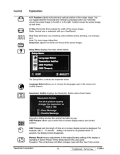
... to use. Exception: This control does not affect changes made with your ViewPanel.) Fine Tune eliminates any remaining video artifacts (noise, banding, out-of the screen image. (Note: Vertical size is not pushed within 15 seconds, the display screen disappears. Do Not Copy VX500-1 You can toggle between Horizontal and Vertical by pressing button [2]. Setup Menu displays the menu shown below. Disable Message Resolution Notice advises the optimal resolution to move the on -screen display screen...
... to use. Exception: This control does not affect changes made with your ViewPanel.) Fine Tune eliminates any remaining video artifacts (noise, banding, out-of the screen image. (Note: Vertical size is not pushed within 15 seconds, the display screen disappears. Do Not Copy VX500-1 You can toggle between Horizontal and Vertical by pressing button [2]. Setup Menu displays the menu shown below. Disable Message Resolution Notice advises the optimal resolution to move the on -screen display screen...
Service Manual
Page 18
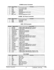
...: D-SUB Red Video Green Video Blue Video Ground Ground Red Video Ground Green Video Ground Blue Video Ground DDCVCC Function ViewSonic Corporation 15 Confidential - No connection Reserved. No connection TMDS negative differential input, channel 1 TMDS positive differential input, channel 1 Logic Ground Reserved. Do Not Copy VX500-1 CONB8 Inverter Connector Pin # 1 2 3 4 5 6 7 Signal Name VCC VCC GND GND PENBKL GND BR_CTRL Function +12 V power supply +12 V power supply GROUND GROUND Penal Backlight On/Off control GROUND Dimming (Brightness) Control CONB5: DC Power Connector Pin...
...: D-SUB Red Video Green Video Blue Video Ground Ground Red Video Ground Green Video Ground Blue Video Ground DDCVCC Function ViewSonic Corporation 15 Confidential - No connection Reserved. No connection TMDS negative differential input, channel 1 TMDS positive differential input, channel 1 Logic Ground Reserved. Do Not Copy VX500-1 CONB8 Inverter Connector Pin # 1 2 3 4 5 6 7 Signal Name VCC VCC GND GND PENBKL GND BR_CTRL Function +12 V power supply +12 V power supply GROUND GROUND Penal Backlight On/Off control GROUND Dimming (Brightness) Control CONB5: DC Power Connector Pin...
Service Manual
Page 21
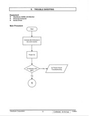
Yes 1 A. 6. TROUBLE SHOOTING Equipment • ViewSonic VX500 LCD Monitor • Personal Computer • Screw Driver Main Procedure ( Start ) Connect all of devices to the LCD monitor Power On Is indicator LED light? Do Not Copy VX500-1 Power Circuit Troubleshooting / ViewSonic Corporation 18 Confidential -
Yes 1 A. 6. TROUBLE SHOOTING Equipment • ViewSonic VX500 LCD Monitor • Personal Computer • Screw Driver Main Procedure ( Start ) Connect all of devices to the LCD monitor Power On Is indicator LED light? Do Not Copy VX500-1 Power Circuit Troubleshooting / ViewSonic Corporation 18 Confidential -
Service Manual
Page 24
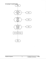
Backlight Troubleshooting ( Start ) ( Change Inverter and End Retry ( )• Change Main Board& End Retry ( Backlight Change Module End No Trouble Found ( End ) ViewSonic Corporation 21 Confidential - B. Do Not Copy VX500-1
Backlight Troubleshooting ( Start ) ( Change Inverter and End Retry ( )• Change Main Board& End Retry ( Backlight Change Module End No Trouble Found ( End ) ViewSonic Corporation 21 Confidential - B. Do Not Copy VX500-1
Service Manual
Page 25
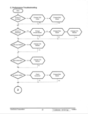
S Check Connector YES No 2 Change Main NO Board YES Change LCD ) Module YES ViewSonic Corporation 22 Confidential - YES NO Change LCD Module YES Change Main Board YES Change Main Board YES Bad Uniformity? Do Not Copy VX500-1 YES Change NO Inverter Board YES 4 LCD Line Defect? C. Performance Troubleshooting Start Screen is flickering? Change VGA Yes Cable 0 YES NO Screen is scrolling? YES Change LCD Module YES Is screen white?
S Check Connector YES No 2 Change Main NO Board YES Change LCD ) Module YES ViewSonic Corporation 22 Confidential - YES NO Change LCD Module YES Change Main Board YES Change Main Board YES Bad Uniformity? Do Not Copy VX500-1 YES Change NO Inverter Board YES 4 LCD Line Defect? C. Performance Troubleshooting Start Screen is flickering? Change VGA Yes Cable 0 YES NO Screen is scrolling? YES Change LCD Module YES Is screen white?
Service Manual
Page 30
... of the monitor's circuitry shown on the previous page, the analog RGB inputs are amplified and sent through an analog-to-digital converter (ADC) to run the LCD panel and the inverter driving the display's backlights. In reference of the block diagram of the horizontal and vertical sync signals, generates a fixed-polarity synchronized clock signal and provides data for controlling LCA panel. BLOCK B. Do Not Copy VX500-1 SYNC SIGNAL PROCESSOR. BLOCK C. ViewSonic Corporation...
... of the monitor's circuitry shown on the previous page, the analog RGB inputs are amplified and sent through an analog-to-digital converter (ADC) to run the LCD panel and the inverter driving the display's backlights. In reference of the block diagram of the horizontal and vertical sync signals, generates a fixed-polarity synchronized clock signal and provides data for controlling LCA panel. BLOCK B. Do Not Copy VX500-1 SYNC SIGNAL PROCESSOR. BLOCK C. ViewSonic Corporation...
Service Manual
Page 31
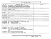
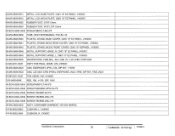
... WARRANTY,VE150X-AA A-AU-0120-0026 CABLE, AUDIO, PC99 GREEN HEAD, 180cm, VE150S-A A/VE150L-AA A-CD-VX500 CD, USER'S GUIDE/INSTALL SOFTWARE/REGISTRAT ION/Web LINKS, VIEW SONIC, VX500C A-UG-0107-0456 MANUAL, USER'S GUIDE, MULTILINGUAL, VIEW SONIC, VX500C B-MB-0201-0579 ASS'Y MAIN, LM, CMO 15" M150X2-T03 (MVA) T-PANEL, SAGE, ANALOG+MIC/B, VIEW SONIC, VX500C M-LCD-0826-0087 ASS'Y BEZEL LCD, H90405KB/H90402B4, ANALOG+AUDIO+MIC/B, T-MVA PANEL, VX500C M-MS-0808-6906 ABS...
... WARRANTY,VE150X-AA A-AU-0120-0026 CABLE, AUDIO, PC99 GREEN HEAD, 180cm, VE150S-A A/VE150L-AA A-CD-VX500 CD, USER'S GUIDE/INSTALL SOFTWARE/REGISTRAT ION/Web LINKS, VIEW SONIC, VX500C A-UG-0107-0456 MANUAL, USER'S GUIDE, MULTILINGUAL, VIEW SONIC, VX500C B-MB-0201-0579 ASS'Y MAIN, LM, CMO 15" M150X2-T03 (MVA) T-PANEL, SAGE, ANALOG+MIC/B, VIEW SONIC, VX500C M-LCD-0826-0087 ASS'Y BEZEL LCD, H90405KB/H90402B4, ANALOG+AUDIO+MIC/B, T-MVA PANEL, VX500C M-MS-0808-6906 ABS...
Service Manual
Page 39
... Not Copy VX500-1 M-MS-0808-6914 METAL, LCD, BASE PLATE, CMO 15" EZ PANEL, VX500C M-MS-0808-6915 METAL, LCD, NECK PLATE, CMO 15" EZ PANEL, VX500C M-MS-0808-6825 RUBBER FOOT, D1511.5mm M-MS-0808-6954 RUBBER FOOT, W15*L7011.5mm M-SCW-0824-0545 SCREW-MM-FLT-BK...-4*8 M-MS-0808-6836 TUBE, HEAT SHRINKABLE, FUE-5A, 5d M-MS-0808-6940 PLASTIC, STAND, BASE COVER, CMO 15" EZ PANEL, VX500C M-MS-0808-6941 PLASTIC, STAND, NECK REAR COVER, CMO 15" EZ PANEL, VX500C M-MS-0808-6942 PLASTIC, STAND, NECK FRONT COVER, CMO 15" EZPANEL, VX500C M-MS-0808-6948 METAL, SUPPORT, HINGE, R, CMO 15" EZ PANEL...
... Not Copy VX500-1 M-MS-0808-6914 METAL, LCD, BASE PLATE, CMO 15" EZ PANEL, VX500C M-MS-0808-6915 METAL, LCD, NECK PLATE, CMO 15" EZ PANEL, VX500C M-MS-0808-6825 RUBBER FOOT, D1511.5mm M-MS-0808-6954 RUBBER FOOT, W15*L7011.5mm M-SCW-0824-0545 SCREW-MM-FLT-BK...-4*8 M-MS-0808-6836 TUBE, HEAT SHRINKABLE, FUE-5A, 5d M-MS-0808-6940 PLASTIC, STAND, BASE COVER, CMO 15" EZ PANEL, VX500C M-MS-0808-6941 PLASTIC, STAND, NECK REAR COVER, CMO 15" EZ PANEL, VX500C M-MS-0808-6942 PLASTIC, STAND, NECK FRONT COVER, CMO 15" EZPANEL, VX500C M-MS-0808-6948 METAL, SUPPORT, HINGE, R, CMO 15" EZ PANEL...


