Service Manual
Page 2
DCN1648 Approval T. Sears ii VE150(b)-2 Service Manual Further, ViewSonic reserves the right to revise this document are the property of their respective owners. Copyright Copyright © 2001 by any means, electronic, mechanical, magnetic, optical, chemical, manual or otherwise, without obligation of ViewSonic to the contents hereof and specifically disclaims any form or by ViewSonic Corporation. Disclaimer ViewSonic makes no representations or warranties...
DCN1648 Approval T. Sears ii VE150(b)-2 Service Manual Further, ViewSonic reserves the right to revise this document are the property of their respective owners. Copyright Copyright © 2001 by any means, electronic, mechanical, magnetic, optical, chemical, manual or otherwise, without obligation of ViewSonic to the contents hereof and specifically disclaims any form or by ViewSonic Corporation. Disclaimer ViewSonic makes no representations or warranties...
Service Manual
Page 3
SPECIFICATIONS 4. PARTS LIST 1 2 2-4 5-6 7 8-13 14 1720 21 22-23 24-30 iii VE150(b)-2 Service Manual SERVICE TOOLS & EQUIPMENT 3. TROUBLESHOOTING FLOW CHART 10. ADJUSTMENTS 11. BLOCK DIAGRAM 6. WIRING DIAGRAM 8. PRECAUTIONS & SAFETY NOTICES 2. SCHEMATIC DIAGRAMS 7. TABLE OF CONTENTS 1. EXPLODED VIEW & PARTS LIST 5. PCB LAYOUT 9.
SPECIFICATIONS 4. PARTS LIST 1 2 2-4 5-6 7 8-13 14 1720 21 22-23 24-30 iii VE150(b)-2 Service Manual SERVICE TOOLS & EQUIPMENT 3. TROUBLESHOOTING FLOW CHART 10. ADJUSTMENTS 11. BLOCK DIAGRAM 6. WIRING DIAGRAM 8. PRECAUTIONS & SAFETY NOTICES 2. SCHEMATIC DIAGRAMS 7. TABLE OF CONTENTS 1. EXPLODED VIEW & PARTS LIST 5. PCB LAYOUT 9.
Service Manual
Page 4
.... ViewSonic Corporation Confidential - Have it . Keep wires in circuit board, keep this manual carefully. There is high-voltage parts inside that may cause damage to the monitor as well as to repair the monitor your local dealer or power company. ♦ Use only the special power adapter that a user's safety comes first. SERVICE NOTES 1. When replacing parts or circuit boards, clamp the lead wires around terminals before cleaning it checked...
.... ViewSonic Corporation Confidential - Have it . Keep wires in circuit board, keep this manual carefully. There is high-voltage parts inside that may cause damage to the monitor as well as to repair the monitor your local dealer or power company. ♦ Use only the special power adapter that a user's safety comes first. SERVICE NOTES 1. When replacing parts or circuit boards, clamp the lead wires around terminals before cleaning it checked...

Service Manual
Page 6
... 15.000ms 13.714ms 1.114ms 0.086ms 0.000ms -/No. 4 640x480 75HZ 31.500MHZ 26.667us 20.317us 3.810us 2.032us 0.000us 13.334ms 12.800ms 0.427ms 0.080ms 0.000ms -/No. 5 800x600 60HZ 40.000MHZ 26.400us 20.000us 2.200us 3.200us 0.000us 16.579ms 15.840ms 0.607ms 0.106ms 0.000ms +1+ No. No. FACTORY PRESET MODE TIMING CHART I 11 \I - +/+ -/- No. VE150(b)-2 Service Manual 3.2. ViewSonic...
... 15.000ms 13.714ms 1.114ms 0.086ms 0.000ms -/No. 4 640x480 75HZ 31.500MHZ 26.667us 20.317us 3.810us 2.032us 0.000us 13.334ms 12.800ms 0.427ms 0.080ms 0.000ms -/No. 5 800x600 60HZ 40.000MHZ 26.400us 20.000us 2.200us 3.200us 0.000us 16.579ms 15.840ms 0.607ms 0.106ms 0.000ms +1+ No. No. FACTORY PRESET MODE TIMING CHART I 11 \I - +/+ -/- No. VE150(b)-2 Service Manual 3.2. ViewSonic...
Service Manual
Page 7
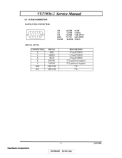
D-SUB CONNECTOR D-SUB 15 PIN CONNECTOR \.., 1 2 3 4 5 0 0 6 7 8 9 10 0 0 0 0 0 11 12 13 14 15 0 0000 1.R 2.G 3.B 4.NC 5.GND 6.GND 11.NC 7.GND 12.SDA 8.GND 13.H.SYNC 9. +5V 14.V.SYNC 10.GND 15.SCL SIGNAL LEVEL CONNECTOR R G B H V SDA SCL SIGNAL RED GREEN BLUE H/SYNC V/SYNC DDC1/2B DDC 1 /2B DESCRIPTION 0.7vp-p(VIDEO) 0.7vp-p(VIDEO) 0.7vp-p(VIDEO) TTL positive or negative TTL positive or negative TTL TTL ViewSonic Corporation -4Confidentipt - VEl50(b)-2 Service Manual 3.3. Do Not Copy 6/29/2001
D-SUB CONNECTOR D-SUB 15 PIN CONNECTOR \.., 1 2 3 4 5 0 0 6 7 8 9 10 0 0 0 0 0 11 12 13 14 15 0 0000 1.R 2.G 3.B 4.NC 5.GND 6.GND 11.NC 7.GND 12.SDA 8.GND 13.H.SYNC 9. +5V 14.V.SYNC 10.GND 15.SCL SIGNAL LEVEL CONNECTOR R G B H V SDA SCL SIGNAL RED GREEN BLUE H/SYNC V/SYNC DDC1/2B DDC 1 /2B DESCRIPTION 0.7vp-p(VIDEO) 0.7vp-p(VIDEO) 0.7vp-p(VIDEO) TTL positive or negative TTL positive or negative TTL TTL ViewSonic Corporation -4Confidentipt - VEl50(b)-2 Service Manual 3.3. Do Not Copy 6/29/2001
Service Manual
Page 9
...-0714-0020 PL-HD-0705-0070 VENDOR PART DESCRIPTION PANEL JT166E VS VE150 ABS94HB/GY7521 PANEL VS VE150B ABS94HBIMidnight GRAY PUSH BUTTON JT166E ABS 94HBIGY7521 PUSH BUTTON JTI66E ABS 94HB/MIDNIGHT GRAY INDICATOR JT156E2 POWER LED PMMA 94HB SCREW,BND T+ M3X8(BND T+) NAME PLATE JD144V3 VIEWSONIC 3BIRDS AL METAL FITTG JT166E SECC 1.0t 15'"LCD CPT SCREW,BND+ M3*12 (BND+) WITH NYLOK...
...-0714-0020 PL-HD-0705-0070 VENDOR PART DESCRIPTION PANEL JT166E VS VE150 ABS94HB/GY7521 PANEL VS VE150B ABS94HBIMidnight GRAY PUSH BUTTON JT166E ABS 94HBIGY7521 PUSH BUTTON JTI66E ABS 94HB/MIDNIGHT GRAY INDICATOR JT156E2 POWER LED PMMA 94HB SCREW,BND T+ M3X8(BND T+) NAME PLATE JD144V3 VIEWSONIC 3BIRDS AL METAL FITTG JT166E SECC 1.0t 15'"LCD CPT SCREW,BND+ M3*12 (BND+) WITH NYLOK...
Service Manual
Page 10
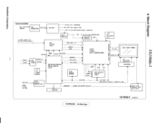
... • OSD DISPLAY T8570D I006 U NN 48 Bits H LCD FLAT PANEL a SHFCLK,DE, E. LuelBe!a Vole '5 BLOCK DIAGRAM AC 110-220V AC 12V IN INPUT ADAPTOR DC/DC 12V for INVERTER 5VCC for panel VDD 5V for Microprocessor (system) D-SUB 15PIN I/P R,G,B analog Input ADC AD9884 1003 I010 AMC7585 RGB 24bit x ... for LCD CONTROLLER 1007,D010 TOREX2V5 +2V5 OSC. 14.318MHZ X001 L. -ID- A\ TO BACKLIGHT High Volt INVERTER SDA/SCL FROM D-SUB 15 PIN I102 24LC21 EEPROM DDC / KeyPad I2C BUS PANELPWR (PANEL VDD ON/OFF Control) I2C BUS (Brightness Control) BACKLIT & BR 5V Panel VDD Control CET...
... • OSD DISPLAY T8570D I006 U NN 48 Bits H LCD FLAT PANEL a SHFCLK,DE, E. LuelBe!a Vole '5 BLOCK DIAGRAM AC 110-220V AC 12V IN INPUT ADAPTOR DC/DC 12V for INVERTER 5VCC for panel VDD 5V for Microprocessor (system) D-SUB 15PIN I/P R,G,B analog Input ADC AD9884 1003 I010 AMC7585 RGB 24bit x ... for LCD CONTROLLER 1007,D010 TOREX2V5 +2V5 OSC. 14.318MHZ X001 L. -ID- A\ TO BACKLIGHT High Volt INVERTER SDA/SCL FROM D-SUB 15 PIN I102 24LC21 EEPROM DDC / KeyPad I2C BUS PANELPWR (PANEL VDD ON/OFF Control) I2C BUS (Brightness Control) BACKLIT & BR 5V Panel VDD Control CET...

Service Manual
Page 11
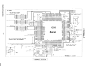
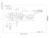
Do Not Copy VE150(b)-2 6/29/2001 Confidential - C035 100uF//6V >>SHSYNC _UC 4 1002A 74F14D SYNC 2,3 >>SVSYNC 2,3,4 The circle are highlight important area for layout and...VCC PVCC P P 2V I CON7 12,00,1u7,11 ,0,.17u0, (7, 2iur P701 8 HEADER wrw...0mNoU0000voU KEY PAD PVVR/LED PSNOLE0 PWFOS $705 5704 03 5702 MEN a.me NV 3E 0701 5701 0 0001 00057 0002 1144148 1N4148 • C161 470oF.../20 VD+M I III D009 BAT54S CO15 2200pF T C010 _j _18PF DDCSDA HSYNC VSYNC DDCSCL DV_Mi RGB Connector D815 T AGNO 135,7548 SOT-2 NM VD.M 10028 I 74F140 >0020 74F140 017 uF 7 R026...
Do Not Copy VE150(b)-2 6/29/2001 Confidential - C035 100uF//6V >>SHSYNC _UC 4 1002A 74F14D SYNC 2,3 >>SVSYNC 2,3,4 The circle are highlight important area for layout and...VCC PVCC P P 2V I CON7 12,00,1u7,11 ,0,.17u0, (7, 2iur P701 8 HEADER wrw...0mNoU0000voU KEY PAD PVVR/LED PSNOLE0 PWFOS $705 5704 03 5702 MEN a.me NV 3E 0701 5701 0 0001 00057 0002 1144148 1N4148 • C161 470oF.../20 VD+M I III D009 BAT54S CO15 2200pF T C010 _j _18PF DDCSDA HSYNC VSYNC DDCSCL DV_Mi RGB Connector D815 T AGNO 135,7548 SOT-2 NM VD.M 10028 I 74F140 >0020 74F140 017 uF 7 R026...

Service Manual
Page 12
t20 51 _95 Dr65 _97 _95 0187 _95 OgA0 DgA1 OgA2 0903 DgA4 0905 DgA6 O947 DgB0 ID9B1 _82 8 0962 _50 _29 DgB4 -25 0g05 O966 -Z7 _26 12967 DbA 72 DbA1 DbA2 DbA3 DbA4 DbA5 DbA6 DbA7 D'2,N COMBO _62 61 DbB3 DbB4 _59 -578 0b05 012B6 56 DbB7 -55 VD 0046 • NC 0005 21 2 0006 NC GIN CO3 NC R048 0 Sub-address:0x98 DATACK /DATACK HSOUT 7 ggE4Rg§iggg?,?,R,HR,P,gEggP,gROne- °- ;*. 9 33.. VE15O(b)-2 6.2. CLAMP 20._ CLKINV R037 NC `IQ- INQFV-12. • PCRAO PCRA1 \ PCRA PCRA4 N P0045 N PCRA6 PCRA7 CLI4EXT 45 FILT 10 REF IN REPOUT ...
t20 51 _95 Dr65 _97 _95 0187 _95 OgA0 DgA1 OgA2 0903 DgA4 0905 DgA6 O947 DgB0 ID9B1 _82 8 0962 _50 _29 DgB4 -25 0g05 O966 -Z7 _26 12967 DbA 72 DbA1 DbA2 DbA3 DbA4 DbA5 DbA6 DbA7 D'2,N COMBO _62 61 DbB3 DbB4 _59 -578 0b05 012B6 56 DbB7 -55 VD 0046 • NC 0005 21 2 0006 NC GIN CO3 NC R048 0 Sub-address:0x98 DATACK /DATACK HSOUT 7 ggE4Rg§iggg?,?,R,HR,P,gEggP,gROne- °- ;*. 9 33.. VE15O(b)-2 6.2. CLAMP 20._ CLKINV R037 NC `IQ- INQFV-12. • PCRAO PCRA1 \ PCRA PCRA4 N P0045 N PCRA6 PCRA7 CLI4EXT 45 FILT 10 REF IN REPOUT ...
Service Manual
Page 13
... \ PCRA1 PCRAO RA2 BAID..7] +21/5 +2V5 0 0 (56 3V 0064 I1wF \\\ \\ \\\\\ tt g as 8`87. ZURAC >>PRA10..71 5 RAID 71 >>POAK1-71 5 Keep the same via on each trace (48 data+l clock) R4 3 R208 10004 2 PCGA(0..71>) 2,4 AOCVSYNC 2 PCBA(1.71)) \ PCGA7 \ P CGA6 \ PCGA5 \ PCGA4 \ ...PRB5 PRB4 POE 5 PVSYNC 070 uF LMX/:r31c5'/-200 00 C071 NC T 7.'72 +2V5 *2V5 XO XI PRB3 / PRB2 / PRBI / PRBO / PGB7 / CO7 0.1uF 0:=12.15-6-° 42V5 C074 1000F/18V PRB[0..7] PG8(0..71 7653" '' -- 1 0 COO 1071' >>PCLK 5 GROUND AROUND >>075810471 5 2 +3.3V > ">7- 277ISY"N.. 6.3. DO 0 +...
... \ PCRA1 PCRAO RA2 BAID..7] +21/5 +2V5 0 0 (56 3V 0064 I1wF \\\ \\ \\\\\ tt g as 8`87. ZURAC >>PRA10..71 5 RAID 71 >>POAK1-71 5 Keep the same via on each trace (48 data+l clock) R4 3 R208 10004 2 PCGA(0..71>) 2,4 AOCVSYNC 2 PCBA(1.71)) \ PCGA7 \ P CGA6 \ PCGA5 \ PCGA4 \ ...PRB5 PRB4 POE 5 PVSYNC 070 uF LMX/:r31c5'/-200 00 C071 NC T 7.'72 +2V5 *2V5 XO XI PRB3 / PRB2 / PRBI / PRBO / PGB7 / CO7 0.1uF 0:=12.15-6-° 42V5 C074 1000F/18V PRB[0..7] PG8(0..71 7653" '' -- 1 0 COO 1071' >>PCLK 5 GROUND AROUND >>075810471 5 2 +3.3V > ">7- 277ISY"N.. 6.3. DO 0 +...

Service Manual
Page 15
...DE 3 CLK C109 33p T33PC112 C 10 ,111 33p 33p The circle are highlight important area for layout and placement. Keep the same via on each trace (48 data+l clock) Vpnl >> • C137 MWG CLK DE VS HS BA7 ...36 35 34 33 32 31 30 29 28 27 26 25 24 23 22 21 20 19 18 17 16 15 14 13 12 10 1 CON46 P006 30 C 29 C 28 C 27 C 26 C 25 C 24 23 C 22 C 21... C 20 C 19 C 18 C 17 C 16 C 15 14 C 13 C 12 C 11 C 10 C9 C 8 C 7 6 0C00O342 Cl CON30 VE150(b)-2 6/29/2001 Confidential - Do Not Copy 6.5. OUTPUT 3 PRAp)..7)> PRAO 1008 PRA1 L010 PRA2 L012 PRA3 1014 PRA4 L016 PRAS...
...DE 3 CLK C109 33p T33PC112 C 10 ,111 33p 33p The circle are highlight important area for layout and placement. Keep the same via on each trace (48 data+l clock) Vpnl >> • C137 MWG CLK DE VS HS BA7 ...36 35 34 33 32 31 30 29 28 27 26 25 24 23 22 21 20 19 18 17 16 15 14 13 12 10 1 CON46 P006 30 C 29 C 28 C 27 C 26 C 25 C 24 23 C 22 C 21... C 20 C 19 C 18 C 17 C 16 C 15 14 C 13 C 12 C 11 C 10 C9 C 8 C 7 6 0C00O342 Cl CON30 VE150(b)-2 6/29/2001 Confidential - Do Not Copy 6.5. OUTPUT 3 PRAp)..7)> PRAO 1008 PRA1 L010 PRA2 L012 PRA3 1014 PRA4 L016 PRAS...
Service Manual
Page 16
Do Not Copy VE150(b)-2 6/29/2001 s1Nm40148 1811 C850 2836 3.1L/F SMD 141 /637 • D 12 EA600004 IOUH 1813 L812 5UH 1506 VCC N 0849 N C83 SMD 0.1uF C840 C838 ... 0828 10000/10V C845 T0.1uF SW/ + C827 1000U/10V 1804 S-818A33AMC SMD Confidential - O 0 O POWER(AC iN 8 DCIDC) P803 L814 5uH 12V )) 0 3 0.1uF _SMD "ry-y , GND>> NA C834 0835 0.1uF SMD 470U/16V Be L810 BACKLIGHT 12V R844 1805 PANEL 5V 12V C844 0.1uF SMD P80 VCC3.30 VCC5 C 2 C 3 C /1 C 5 C 6 0N00 7 7pin 3.3V / 0.5A...
Do Not Copy VE150(b)-2 6/29/2001 s1Nm40148 1811 C850 2836 3.1L/F SMD 141 /637 • D 12 EA600004 IOUH 1813 L812 5UH 1506 VCC N 0849 N C83 SMD 0.1uF C840 C838 ... 0828 10000/10V C845 T0.1uF SW/ + C827 1000U/10V 1804 S-818A33AMC SMD Confidential - O 0 O POWER(AC iN 8 DCIDC) P803 L814 5uH 12V )) 0 3 0.1uF _SMD "ry-y , GND>> NA C834 0835 0.1uF SMD 470U/16V Be L810 BACKLIGHT 12V R844 1805 PANEL 5V 12V C844 0.1uF SMD P80 VCC3.30 VCC5 C 2 C 3 C /1 C 5 C 6 0N00 7 7pin 3.3V / 0.5A...
Service Manual
Page 17
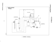
Do Not Copy WIRING DIAGRAM VE150(b)-2 O O LCD ASS'Y INVERTER PCB CON PCB J02 0 O 1'74 O 1P3 0 O DC/DC PCB 0 1801 P98I P980 P'83 P'85 o P006 P014 o P005 g P004 006 MAIN PCB [11'002 P100 P982 O O Vl tv Confidential -
Do Not Copy WIRING DIAGRAM VE150(b)-2 O O LCD ASS'Y INVERTER PCB CON PCB J02 0 O 1'74 O 1P3 0 O DC/DC PCB 0 1801 P98I P980 P'83 P'85 o P006 P014 o P005 g P004 006 MAIN PCB [11'002 P100 P982 O O Vl tv Confidential -
Service Manual
Page 24
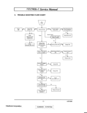
... on display? Yes No 10. Check VP signal is OK? PCB is Yes ► Check if Inverter is in pwr saving state? Yes V Check P005,P006 data bus have signal Yes • Change 1005 LCD controller IC No • Change LCD panel ViewSonic Corporation -21Confidential - Check O001,O002 is Y connect OK? VE150(b)-2 Service Manual 9. TROUBLE SHOOTING FLOW CHART No Display Check Y801 • No Check P104 pin5,6 is 12V Dark Check LED Color Amber Check 1O cable is...
... on display? Yes No 10. Check VP signal is OK? PCB is Yes ► Check if Inverter is in pwr saving state? Yes V Check P005,P006 data bus have signal Yes • Change 1005 LCD controller IC No • Change LCD panel ViewSonic Corporation -21Confidential - Check O001,O002 is Y connect OK? VE150(b)-2 Service Manual 9. TROUBLE SHOOTING FLOW CHART No Display Check Y801 • No Check P104 pin5,6 is 12V Dark Check LED Color Amber Check 1O cable is...
Service Manual
Page 25
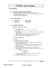
... 1. VE150(b)-2 Service Manual 10. ADJUSTMENT 10.1. Signals: reference the front detail specifications and timing table. Warm up time must be power ON for warm up time: The display must be over 30 minutes. (b). GEOMETRY DESIGNATION FUNCTION KEY FUNCTION KEY 10.3. Adjustment of screen and along a perpendicular to factory setting mode.(fig.1 & fig.2) (e). After auto balance, change full whitw pattern, adjust Contrast & Brightness to save. Do Not Copy 6/29/2001 WHITE...
... 1. VE150(b)-2 Service Manual 10. ADJUSTMENT 10.1. Signals: reference the front detail specifications and timing table. Warm up time must be power ON for warm up time: The display must be over 30 minutes. (b). GEOMETRY DESIGNATION FUNCTION KEY FUNCTION KEY 10.3. Adjustment of screen and along a perpendicular to factory setting mode.(fig.1 & fig.2) (e). After auto balance, change full whitw pattern, adjust Contrast & Brightness to save. Do Not Copy 6/29/2001 WHITE...
Service Manual
Page 26
... Green Gain 150 Switch Color 6500 6500 Blue Gain 146 Red -Cont.(Z) 131 131 Red Offset 20 Green -Cont.(Z) 133 133 Green Offset 24 Blue -Cont.(Z) 122 122 Blue Offset 20 Save 6500 Red -Bri.(Z) 128 Auto Balance Green -Bri.(Z) 128 'nit EEPROM Blue -Bri.(Z) 128 Auto Adjust Previous Page Next Page Save & Exit FACTORY-ADJ VER-01 (FIG.1) FACTORY-ADJ VER-01 (FIG.2) 2. Until all of modes are agjusted, exit OSD menu...
... Green Gain 150 Switch Color 6500 6500 Blue Gain 146 Red -Cont.(Z) 131 131 Red Offset 20 Green -Cont.(Z) 133 133 Green Offset 24 Blue -Cont.(Z) 122 122 Blue Offset 20 Save 6500 Red -Bri.(Z) 128 Auto Balance Green -Bri.(Z) 128 'nit EEPROM Blue -Bri.(Z) 128 Auto Adjust Previous Page Next Page Save & Exit FACTORY-ADJ VER-01 (FIG.1) FACTORY-ADJ VER-01 (FIG.2) 2. Until all of modes are agjusted, exit OSD menu...
Service Manual
Page 29
...DIGITAL MTV212MX64X(MTP) MYSON BEAD,HI-IMPEDANCE 3216MZ 200.000HM I VE150(b)-2 Service Manual...L008 L009 LO10 L011 L012 L013 L014 ViewSonic P/N E-C-0404-3815 E-C-0404-3900 E-C-...E-L-0407-1371 E-L-0407-1371 E-L-0407-1371 VENDOR PART DESCRIPTION CAP,CHIP 85'C 0.I00UF 50V Z ...SWITCH SMD LL4148 3.5X 1.5 GS08 DIODE,RECT(SMD) BAS32L PHILIPS DIODE,SWITCH SMD BAT54SLTI MOTOROLA SOT23 DIODE,SWITCH SMD BAT54SLTI MOTOROLA SOT23 DIODE,SWITCH SMD BAT54SLTI MOTOROLA SOT23 DIODE,SWITCH SMD BAT54SLTI MOTOROLA SOT23 DIODE,SWITCH SMD BAT54SLTI MOTOROLA SOT23 DIODE,SWITCH SMD BAT54SLTI MOTOROLA SOT23 DIODE,SWITCH...
...DIGITAL MTV212MX64X(MTP) MYSON BEAD,HI-IMPEDANCE 3216MZ 200.000HM I VE150(b)-2 Service Manual...L008 L009 LO10 L011 L012 L013 L014 ViewSonic P/N E-C-0404-3815 E-C-0404-3900 E-C-...E-L-0407-1371 E-L-0407-1371 E-L-0407-1371 VENDOR PART DESCRIPTION CAP,CHIP 85'C 0.I00UF 50V Z ...SWITCH SMD LL4148 3.5X 1.5 GS08 DIODE,RECT(SMD) BAS32L PHILIPS DIODE,SWITCH SMD BAT54SLTI MOTOROLA SOT23 DIODE,SWITCH SMD BAT54SLTI MOTOROLA SOT23 DIODE,SWITCH SMD BAT54SLTI MOTOROLA SOT23 DIODE,SWITCH SMD BAT54SLTI MOTOROLA SOT23 DIODE,SWITCH SMD BAT54SLTI MOTOROLA SOT23 DIODE,SWITCH SMD BAT54SLTI MOTOROLA SOT23 DIODE,SWITCH...
Service Manual
Page 32
.../01 VE150(b)-2 Service Manual LOCATION ...E-C-0404-3891 E-C-0404-3891 E-D-0403-1667 E-D-0403-1780 E-IC-0401-2026 E-IC-0401-2018 VENDOR PART DESCRIPTION RES,CHIP 1/10W 4.70K J T1608 RES,CHIP 1/10W 4.70K J TI608 RES,CHIP 1/10W...OSC XTAL 12MHZ CL30P WS LED KINGBRIGHT L-59YGW CONNECTOR B8B-XH-A 8PIN SWITCH,PU-TC P4.5*4P(REF SKHH43A520-SV FW) SWITCH,PU-TC SKHHLH1520-SV PC BOARD JT156E 1 T* CON 94V0... l0y M DIODE,SWITCH SMD L1A148 3.5X 1.5 TEMIC GS08 RECT BRIDGE SMD EA60QC04-TE I6F2 NI T0252 IC,DIGITAL SMD S816A33AMC SEIKO SOT23-5 IC,LINEAR(SMD) HIP6013CB INTERSIL ViewSonic Corporation -29 Confidential...
.../01 VE150(b)-2 Service Manual LOCATION ...E-C-0404-3891 E-C-0404-3891 E-D-0403-1667 E-D-0403-1780 E-IC-0401-2026 E-IC-0401-2018 VENDOR PART DESCRIPTION RES,CHIP 1/10W 4.70K J T1608 RES,CHIP 1/10W 4.70K J TI608 RES,CHIP 1/10W...OSC XTAL 12MHZ CL30P WS LED KINGBRIGHT L-59YGW CONNECTOR B8B-XH-A 8PIN SWITCH,PU-TC P4.5*4P(REF SKHH43A520-SV FW) SWITCH,PU-TC SKHHLH1520-SV PC BOARD JT156E 1 T* CON 94V0... l0y M DIODE,SWITCH SMD L1A148 3.5X 1.5 TEMIC GS08 RECT BRIDGE SMD EA60QC04-TE I6F2 NI T0252 IC,DIGITAL SMD S816A33AMC SEIKO SOT23-5 IC,LINEAR(SMD) HIP6013CB INTERSIL ViewSonic Corporation -29 Confidential...
Service Manual
Page 33
VE150(b)-2 Service Manual LOCATION L8I0 L811 L812 L813 L814(RA) L814(RB) P801 P803 Q801 Q802 R836 R837 R839 R841 R842 R843 R845 U802 P951 P951 P951 P952 P952 P961 P961 P961 P980 P981 P982 P983 P984 P985 U901 V901 Y801(RA) Y801(RA) Y801(RB) Y801(RB) Y801(RC) Y801(RC) ViewSonic P/N E-L-0407-0013...-0808-5496 M-MS-0808-5493 M-MS-0808-5494 B-SB-0221-0203 M-LCD-0826-0069 A-AD-0114-0114 A-AD-0114-0095 A-AD-0114-0115 A-AD-0114-0122 A-AD-0114-0116 A-AD-0114-0118 VENDOR PART DESCRIPTION FERRITE CORE 3.5X9X0.8 COIL,CHOKE JTI56E1 0.8*15.5T 10uH COIL,CHOKE JD156G 15UF 21.5T REF COIL,CHOKE...
VE150(b)-2 Service Manual LOCATION L8I0 L811 L812 L813 L814(RA) L814(RB) P801 P803 Q801 Q802 R836 R837 R839 R841 R842 R843 R845 U802 P951 P951 P951 P952 P952 P961 P961 P961 P980 P981 P982 P983 P984 P985 U901 V901 Y801(RA) Y801(RA) Y801(RB) Y801(RB) Y801(RC) Y801(RC) ViewSonic P/N E-L-0407-0013...-0808-5496 M-MS-0808-5493 M-MS-0808-5494 B-SB-0221-0203 M-LCD-0826-0069 A-AD-0114-0114 A-AD-0114-0095 A-AD-0114-0115 A-AD-0114-0122 A-AD-0114-0116 A-AD-0114-0118 VENDOR PART DESCRIPTION FERRITE CORE 3.5X9X0.8 COIL,CHOKE JTI56E1 0.8*15.5T 10uH COIL,CHOKE JD156G 15UF 21.5T REF COIL,CHOKE...


