
User Manual
Page 2
... Registration 2 IMPORTANT SAFETY INSTRUCTUONS 3 Quick Installation 5 Using the Display (PC 6 PREPARATION 7 OPERATING INSTRUCTIONS 9 Use of the remote control 9 To use the menus 10 Main menu 10 CONNECT PERIPHERAL EQUIPMENT 17 Front Panel Control Knobs 17 Preparation 17 Video recorder 18 Camera, camcorder, Video Game set 19 DVD player 19 Digital Set TOP box 20 Headphone 21 Tips 21 PRODUCT SPECIFICATION 22 Compatibility Modes 24 BEFORE CALLING SERVICE 25 Customer support 26 Glossary 27 Limited Warranty 28 SYMBOL SA 1965...
... Registration 2 IMPORTANT SAFETY INSTRUCTUONS 3 Quick Installation 5 Using the Display (PC 6 PREPARATION 7 OPERATING INSTRUCTIONS 9 Use of the remote control 9 To use the menus 10 Main menu 10 CONNECT PERIPHERAL EQUIPMENT 17 Front Panel Control Knobs 17 Preparation 17 Video recorder 18 Camera, camcorder, Video Game set 19 DVD player 19 Digital Set TOP box 20 Headphone 21 Tips 21 PRODUCT SPECIFICATION 22 Compatibility Modes 24 BEFORE CALLING SERVICE 25 Customer support 26 Glossary 27 Limited Warranty 28 SYMBOL SA 1965...
User Manual
Page 3
... or television reception, which the receiver is encouraged to try to operate the equipment. 2. It is no guarantee that to provide reasonable protection against harmful interference in a particular installation. Increase the separation between the equipment and receiver. 3. Refer servicing to rain or moisture. This manual should be determined by turning the equipment off and on, the user is connected. 4. These...
... or television reception, which the receiver is encouraged to try to operate the equipment. 2. It is no guarantee that to provide reasonable protection against harmful interference in a particular installation. Increase the separation between the equipment and receiver. 3. Refer servicing to rain or moisture. This manual should be determined by turning the equipment off and on, the user is connected. 4. These...
User Manual
Page 5
... time. 15. When a cart is used, use attachments/accessories specified by qualified service personnel when: A. The power supply cord or the plug has been damaged; or E. Do not compromise these materials may contain lead or mercury. Such items could ultimately overturn the product. Power Lines - If an outside antenna is connected to the receiver, be mounted to proper grounding of the mats and supporting...
... time. 15. When a cart is used, use attachments/accessories specified by qualified service personnel when: A. The power supply cord or the plug has been damaged; or E. Do not compromise these materials may contain lead or mercury. Such items could ultimately overturn the product. Power Lines - If an outside antenna is connected to the receiver, be mounted to proper grounding of the mats and supporting...
User Manual
Page 7
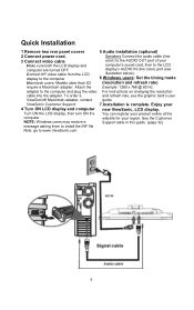
... may receive a Support table in this guide. (page 32) message asking them to the LCD display's AUDIO IN (line color) port (see the graphic card's user ViewSonic® Macintosh adapter, contact guide. Speakers Connect the audio cable (line 3 Connect video cable Make sure both the LCD display and computer are turned OFF Connect the video cable from the LCD display to the computer color) to the AUDIO OUT port of your 4 Turn ON LCD display and computer new ViewSonic, LCD display. Quick Installation 1 Remove two rear panel covers 5 Audio Installation (optional) 2 Connect power cord...
... may receive a Support table in this guide. (page 32) message asking them to the LCD display's AUDIO IN (line color) port (see the graphic card's user ViewSonic® Macintosh adapter, contact guide. Speakers Connect the audio cable (line 3 Connect video cable Make sure both the LCD display and computer are turned OFF Connect the video cable from the LCD display to the computer color) to the AUDIO OUT port of your 4 Turn ON LCD display and computer new ViewSonic, LCD display. Quick Installation 1 Remove two rear panel covers 5 Audio Installation (optional) 2 Connect power cord...
User Manual
Page 8
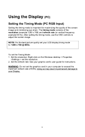
... result in your LCD display timing mode to adjust the screen image. The timing mode consists of the screen image and minimizing eye strain. To set the resolution. 2. Set the refresh rate: See your Display. 6 After setting the timing mode, use the OSD controls to : 1280 x 768 @ 60Hz. Using the Display (PC) Setting the Timing Mode (PC RGB Input) Setting the timing mode is important for instructions. WARNING: Do not set your computer to your graphic card's user guide for maximizing...
... result in your LCD display timing mode to adjust the screen image. The timing mode consists of the screen image and minimizing eye strain. To set the resolution. 2. Set the refresh rate: See your Display. 6 After setting the timing mode, use the OSD controls to : 1280 x 768 @ 60Hz. Using the Display (PC) Setting the Timing Mode (PC RGB Input) Setting the timing mode is important for instructions. WARNING: Do not set your computer to your graphic card's user guide for maximizing...
User Manual
Page 11
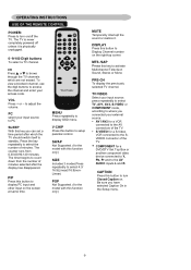
OPERATING INSTRUCTIONS USE OF THE REMOTE CONTROL POWER: Press to turn Closed Caption on. VOL Press + or - The timer begins to activate Multichannel Television Sound, Stereo or Mono PRE-CH To display the previously selected TV channel. POWER DISPLAY MUTE 1 2 3 CH 4 5 6 7 8 9 VOL 100 0 PC TV/VIDEO SLEEP MENU MTS/SAP V-CHIP PIP CAPTION SIZE ViewSonic MENU Press repeatedly to adjust the volume. V-CHIP Press this key to count down from 0,30,60,90,120 minutes. SWAP Not...
OPERATING INSTRUCTIONS USE OF THE REMOTE CONTROL POWER: Press to turn Closed Caption on. VOL Press + or - The timer begins to activate Multichannel Television Sound, Stereo or Mono PRE-CH To display the previously selected TV channel. POWER DISPLAY MUTE 1 2 3 CH 4 5 6 7 8 9 VOL 100 0 PC TV/VIDEO SLEEP MENU MTS/SAP V-CHIP PIP CAPTION SIZE ViewSonic MENU Press repeatedly to adjust the volume. V-CHIP Press this key to count down from 0,30,60,90,120 minutes. SWAP Not...
User Manual
Page 12
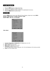
.... Video Adjust 1. Contrast, Brightness and Saturation are adjusted from 0 to default value. 10 TO USE THE MENUS 1. Adjust item include VIDEO ADJUST, AUDIO ADJUST, CLOSED CAPTION ,V-CHIP, SLEEP TIMER , SET UP and PC ADJUST. Press the MENU button to the levels you prefer. 5. Sharpness is adjusted from 0 to 100. 2. You can adjust picture contrast, brightness, color, tint and sharpness to exit the menu. MAIN MENU Press the MENU button into the main OSD (On Screen Display). Black Level is adjusted...
.... Video Adjust 1. Contrast, Brightness and Saturation are adjusted from 0 to default value. 10 TO USE THE MENUS 1. Adjust item include VIDEO ADJUST, AUDIO ADJUST, CLOSED CAPTION ,V-CHIP, SLEEP TIMER , SET UP and PC ADJUST. Press the MENU button to the levels you prefer. 5. Sharpness is adjusted from 0 to 100. 2. You can adjust picture contrast, brightness, color, tint and sharpness to exit the menu. MAIN MENU Press the MENU button into the main OSD (On Screen Display). Black Level is adjusted...
User Manual
Page 17
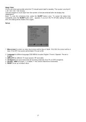
... when no video input screen will be blue or blank. CH Search is English. 3. Blue screen for auto memorizes all receiving channels of minutes selected after which the TV should switch itself to standby. Note: To view the remaining time, press the SLEEP button once. If you turn the TV off after setting the sleep time, the setting will be erased. AIR/CATV for different language OSD MENU includes...
... when no video input screen will be blue or blank. CH Search is English. 3. Blue screen for auto memorizes all receiving channels of minutes selected after which the TV should switch itself to standby. Note: To view the remaining time, press the SLEEP button once. If you turn the TV off after setting the sleep time, the setting will be erased. AIR/CATV for different language OSD MENU includes...
User Manual
Page 19
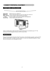
.... CONNECT PERIPHERAL EQUIPMENT FRONT PANEL CONTROL KNOBS Power Key: Press to damage the screen. 17 MENU Key: Press to select your function selection and adjustment. Source Key: Press to show you how to confirm your input source. The following connection diagrams show the OSD menu and exit OSD menu at the back of video and audio equipment that can be easier to your precautions not to turn...
.... CONNECT PERIPHERAL EQUIPMENT FRONT PANEL CONTROL KNOBS Power Key: Press to damage the screen. 17 MENU Key: Press to select your function selection and adjustment. Source Key: Press to show you how to confirm your input source. The following connection diagrams show the OSD menu and exit OSD menu at the back of video and audio equipment that can be easier to your precautions not to turn...
User Manual
Page 20
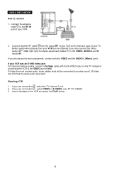
... equipment) cables to provide sound. (S-Video and AV2 has the same audio input port) Watching VCR 1. Connect the antenna cable to the RF IN port of your VCR to connect 1. S-Video does not provide audio, audio cables must still be obtained if you use connection , select the TV channel 3 or 4. 2. Better quality when playing from the output RF of your VCR. 2. Insert videotape in the VCR and press the PLAY button. 18...
... equipment) cables to provide sound. (S-Video and AV2 has the same audio input port) Watching VCR 1. Connect the antenna cable to the RF IN port of your VCR to connect 1. S-Video does not provide audio, audio cables must still be obtained if you use connection , select the TV channel 3 or 4. 2. Better quality when playing from the output RF of your VCR. 2. Insert videotape in the VCR and press the PLAY button. 18...
User Manual
Page 21
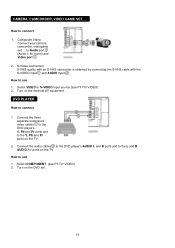
... VIDEO or S-VIDEO input source (see P7 TV/ VIDEO) 2. Turn on the TV. to connect 1. How to the DVD player's. Connect the three separate component video cables to use 1. Turn on the TV. 2. How to connect 1. S-Video Connection S-VHS quality with an S-VHS camcorder is obtained by connecting the S-VHS cable with the S-VIDEO input and AUDIO input . DVD PLAYER How to use 1. Y, Pb and Pr ports and to the L and R AUDIO AV ports on the external AV equipment. CAMERA, CAMCORDER, VIDEO GAME SET...
... VIDEO or S-VIDEO input source (see P7 TV/ VIDEO) 2. Turn on the TV. to connect 1. How to the DVD player's. Connect the three separate component video cables to use 1. Turn on the TV. 2. How to connect 1. S-Video Connection S-VHS quality with an S-VHS camcorder is obtained by connecting the S-VHS cable with the S-VIDEO input and AUDIO input . DVD PLAYER How to use 1. Y, Pb and Pr ports and to the L and R AUDIO AV ports on the external AV equipment. CAMERA, CAMCORDER, VIDEO GAME SET...
User Manual
Page 22
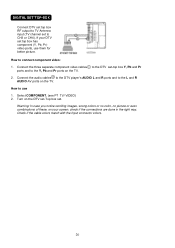
Connect the audio cables to the DTV player's AUDIO L and R ports and to the L and R AUDIO AV ports on your DTV set -top box Y, Pb and Pr ports and to the Y, Pb and Pr ports on the DTV set-Top box set to CH3 or CH4). How to connect component video: 1. DIGITAL SET TOP BOX Connect DTV set top box RF output to TV Antenna input (TV channel set . Warning: In case you notice scrolling images, wrong colors or no color, no...
Connect the audio cables to the DTV player's AUDIO L and R ports and to the L and R AUDIO AV ports on your DTV set -top box Y, Pb and Pr ports and to the Y, Pb and Pr ports on the DTV set-Top box set to CH3 or CH4). How to connect component video: 1. DIGITAL SET TOP BOX Connect DTV set top box RF output to TV Antenna input (TV channel set . Warning: In case you notice scrolling images, wrong colors or no color, no...
User Manual
Page 23
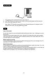
... muted. Note: When a TV channel or external AV source is blocked because of a rating set via the Parental control menu, also the headphone is located at the rear corner of . Do not use a clean, damp cloth. The MUTE key on the remote control works on both internal speaker and the earphone. 3. Use volume key to adjust the volume. If the screen requires additional cleaning, use liquid cleaners or aerosol cleaners.
... muted. Note: When a TV channel or external AV source is blocked because of a rating set via the Parental control menu, also the headphone is located at the rear corner of . Do not use a clean, damp cloth. The MUTE key on the remote control works on both internal speaker and the earphone. 3. Use volume key to adjust the volume. If the screen requires additional cleaning, use liquid cleaners or aerosol cleaners.
User Manual
Page 25
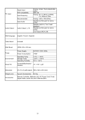
PC Input Audio Output Signal Input PnP compatibility Input frequency Recommended Input Audio Audio Output: L / R Analog: D-Sub 15 pin (detachable cable) DDC 2B Analog: FH: 31.5KHz to 49KHz FV: 56Hz to 75Hz Analog: 1280 x 768 (60Hz) Headphone Mini-jack for stereo (3.5ø) Speaker (built-in): Two 5 watt speakers Headphone Mini-jack for stereo (3.5ø) Line Output (RCA L/R) OSD language English / French / Spanish Table Stand Included Wall Mount Power Environment Panel Tilt VESA 100 x 100 mm Power Supply AC100V~120V, 60Hz Power Consumption
PC Input Audio Output Signal Input PnP compatibility Input frequency Recommended Input Audio Audio Output: L / R Analog: D-Sub 15 pin (detachable cable) DDC 2B Analog: FH: 31.5KHz to 49KHz FV: 56Hz to 75Hz Analog: 1280 x 768 (60Hz) Headphone Mini-jack for stereo (3.5ø) Speaker (built-in): Two 5 watt speakers Headphone Mini-jack for stereo (3.5ø) Line Output (RCA L/R) OSD language English / French / Spanish Table Stand Included Wall Mount Power Environment Panel Tilt VESA 100 x 100 mm Power Supply AC100V~120V, 60Hz Power Consumption
User Manual
Page 27
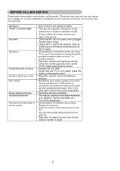
... receiver installation and adjustments of your TV. *Select the TV mode to be caused by electrical interference (e.g. Replace if necessary *Clean the remote control sensor lens on the TV again. *Check antenna connections at the front of customer controls are working. These tips may be sure your warranty. Symptoms ″Ghost″ or double image No power No picture Good picture but no sound Good sound but poor color...
... receiver installation and adjustments of your TV. *Select the TV mode to be caused by electrical interference (e.g. Replace if necessary *Clean the remote control sensor lens on the TV again. *Check antenna connections at the front of customer controls are working. These tips may be sure your warranty. Symptoms ″Ghost″ or double image No power No picture Good picture but no sound Good sound but poor color...
User Manual
Page 29
... signal design used for the input of the receiver these connectors (RCA phono type plug) are used as Super VHS video-cassette recorder, Laser Disc player and DVD Home Theater Set) in order to provide maximum consumer viewing satisfaction. 27 S-Video Input You can set to a high-resolution video source (such as the carrier for use with the TV picture. GLOSSARY Audio / Video Inputs Located on the TV screen is made available for user adjustments. MPAA Motion Picture...
... signal design used for the input of the receiver these connectors (RCA phono type plug) are used as Super VHS video-cassette recorder, Laser Disc player and DVD Home Theater Set) in order to provide maximum consumer viewing satisfaction. 27 S-Video Input You can set to a high-resolution video source (such as the carrier for use with the TV picture. GLOSSARY Audio / Video Inputs Located on the TV screen is made available for user adjustments. MPAA Motion Picture...
User Manual
Page 30
... warranty is effective: Viewsonic N1750w TV is valid only for all labor from state to follow instructions supplied with a like product. Damage, deterioration or malfunction resulting from defects in the original container to an authorized ViewSonic service center or ViewSonic. 4. Repair or attempted repair by anyone not authorized by ViewSonic. Removal or installation of supplies or parts not meeting ViewSonic's specifications. Use of the product. For information about receiving service...
... warranty is effective: Viewsonic N1750w TV is valid only for all labor from state to follow instructions supplied with a like product. Damage, deterioration or malfunction resulting from defects in the original container to an authorized ViewSonic service center or ViewSonic. 4. Repair or attempted repair by anyone not authorized by ViewSonic. Removal or installation of supplies or parts not meeting ViewSonic's specifications. Use of the product. For information about receiving service...

User Manual
Page 31
... and Canada the male plug is going to replace the original cord set or if the cord set must use only a shielded BNC(5) cable. If a BNC cable is a NEMA5-15 style (Figure A2), IL Listed, and CSA labeled. The cord set for power cords used , use a grounded power supply cord and the provided shielded video interface cable with the limits for help. Cord Type Size of Conductors in accordance with the original power supply, part number: 12VDC LSE9901B1250, 12VDC...
... and Canada the male plug is going to replace the original cord set or if the cord set must use only a shielded BNC(5) cable. If a BNC cable is a NEMA5-15 style (Figure A2), IL Listed, and CSA labeled. The cord set for power cords used , use a grounded power supply cord and the provided shielded video interface cable with the limits for help. Cord Type Size of Conductors in accordance with the original power supply, part number: 12VDC LSE9901B1250, 12VDC...
Brochure
Page 1
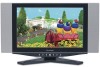
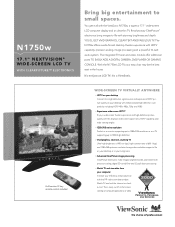
... of computer applications or video. Full-function 51-key remote control included WIDE-SCREEN TV VIRTUALLY ANYWHERE > HDTV on your desktop Connect to small spaces. N1750w 17.1" NEXTVISION® WIDE-SCREEN LCD TV WITH CLEARPICTURE™ ELECTRONICS Bring big entertainment to a high definition signal source and experience HDTV picture quality on your desktop with enhanced and high-definition compatibility including HDTV: 480i, 480p, 720p and...
... of computer applications or video. Full-function 51-key remote control included WIDE-SCREEN TV VIRTUALLY ANYWHERE > HDTV on your desktop Connect to small spaces. N1750w 17.1" NEXTVISION® WIDE-SCREEN LCD TV WITH CLEARPICTURE™ ELECTRONICS Bring big entertainment to a high definition signal source and experience HDTV picture quality on your desktop with enhanced and high-definition compatibility including HDTV: 480i, 480p, 720p and...
Brochure
Page 2
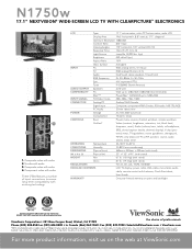
... Signal input Composite, component YPbPr, S-video, RCA audio, 1xRF (TV), RGB PC Audio 3.5mm stereo mini POWER Voltage AC 100-240V (universal) Consumption 75-watts (max) CONTROLS Basic Power, menu, source, channel up/down, volume up to ensure long-term compatibility with batteries, Quick Start sheet, User Guide WARRANTY One-year limited warranty on the web at ViewSonic.com N1750w 17.1" NEXTVISION® WIDE-SCREEN LCD TV WITH CLEARPICTURE™ ELECTRONICS 1 4 2 3 1. Component video with audio 3. Analog adapter available from ViewSonic...
... Signal input Composite, component YPbPr, S-video, RCA audio, 1xRF (TV), RGB PC Audio 3.5mm stereo mini POWER Voltage AC 100-240V (universal) Consumption 75-watts (max) CONTROLS Basic Power, menu, source, channel up/down, volume up to ensure long-term compatibility with batteries, Quick Start sheet, User Guide WARRANTY One-year limited warranty on the web at ViewSonic.com N1750w 17.1" NEXTVISION® WIDE-SCREEN LCD TV WITH CLEARPICTURE™ ELECTRONICS 1 4 2 3 1. Component video with audio 3. Analog adapter available from ViewSonic...


