English Owners Manual
Page 2
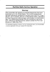
The channel assignments include frequencies assigned for use in these frequencies without an individual license, please contact the FCC Call Center at 1-888-CALL-FCC. For frequencies/channels that have restricted use in Canada, and use of the U.S. Maritime Radio Services Operation Warning! Coast Guard, use in the U.S. This transmitter will operate on channels/frequencies that are currently for exclusive use in international waters. Operation in the United States. For...
The channel assignments include frequencies assigned for use in these frequencies without an individual license, please contact the FCC Call Center at 1-888-CALL-FCC. For frequencies/channels that have restricted use in Canada, and use of the U.S. Maritime Radio Services Operation Warning! Coast Guard, use in the U.S. This transmitter will operate on channels/frequencies that are currently for exclusive use in international waters. Operation in the United States. For...

English Owners Manual
Page 3
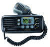
... Channel 16 communications. 6. Controls transmitter's output power between US and International Channels. 7. INT (USA/International) - VOLUME/On/Off - Turns the SOLARA power on or off and adjusts the volume. Controls 4 Controls and Indicators 1 23 567 8 1. Indicators for Channel Number, 16, INT, 1W and TX. 3. L/M CHANNEL Selectors - SQUELCH - CH16 - Controls the background noise when a signal is not received. 4. Press to transmit and release to select the desired communication channel. 2. These controls are used to receive. 5. Switches operation...
... Channel 16 communications. 6. Controls transmitter's output power between US and International Channels. 7. INT (USA/International) - VOLUME/On/Off - Turns the SOLARA power on or off and adjusts the volume. Controls 4 Controls and Indicators 1 23 567 8 1. Indicators for Channel Number, 16, INT, 1W and TX. 3. L/M CHANNEL Selectors - SQUELCH - CH16 - Controls the background noise when a signal is not received. 4. Press to transmit and release to select the desired communication channel. 2. These controls are used to receive. 5. Switches operation...

English Owners Manual
Page 4
... displayed as two digits (Example: 01, 02, 03, etc.). ANT. (Antenna) Connector - The connecting wire must use . Indicates PTT switch is selected. 10. LO - REMOTE Speaker Connector - Indicates that Channel 16 is pressed. 13. Indicates transmitted output is 1 Watt. 12. Indicates Channel Number in use the included 3.5mm miniature plug. 16. Connect black power lead to negative power source. Connect the antenna here using a PL259 type connector. 15. DC Power Cord with In-line Fuse Holder - Indicates International Channel Mode...
... displayed as two digits (Example: 01, 02, 03, etc.). ANT. (Antenna) Connector - The connecting wire must use . Indicates PTT switch is selected. 10. LO - REMOTE Speaker Connector - Indicates that Channel 16 is pressed. 13. Indicates transmitted output is 1 Watt. 12. Indicates Channel Number in use the included 3.5mm miniature plug. 16. Connect black power lead to negative power source. Connect the antenna here using a PL259 type connector. 15. DC Power Cord with In-line Fuse Holder - Indicates International Channel Mode...
English Owners Manual
Page 5
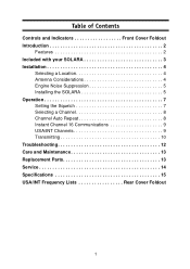
Table of Contents Controls and Indicators Front Cover Foldout Introduction 2 Features 2 Included with your SOLARA 3 Installation 4 Selecting a Location 4 Antenna Considerations 4 Engine Noise Suppression 5 Installing the SOLARA 5 Operation 7 Setting the Squelch 7 Selecting a Channel 8 Channel Auto Repeat 8 Instant Channel 16 Communications 9 USA/INT Channels 9 Transmitting 10 Troubleshooting 12 Care and Maintenance 13 Replacement Parts 13 Service 14 Specifications 15 USA/INT Frequency Lists Rear Cover Foldout 1
Table of Contents Controls and Indicators Front Cover Foldout Introduction 2 Features 2 Included with your SOLARA 3 Installation 4 Selecting a Location 4 Antenna Considerations 4 Engine Noise Suppression 5 Installing the SOLARA 5 Operation 7 Setting the Squelch 7 Selecting a Channel 8 Channel Auto Repeat 8 Instant Channel 16 Communications 9 USA/INT Channels 9 Transmitting 10 Troubleshooting 12 Care and Maintenance 13 Replacement Parts 13 Service 14 Specifications 15 USA/INT Frequency Lists Rear Cover Foldout 1
English Owners Manual
Page 6
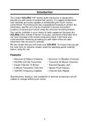
...; Receives 10 Weather Channels • Transmits 54 Marine Channels • External Speaker Jack • Splash Proof Chassis • Channel Auto Repeat Specifications, features, and availability of optional accessories are easily capable of withstanding the harsh marine environment. You can be mounted in your SOLARA. It will enjoy your choice of radio equipment because the SOLARA offers Instant Channel 16 access, automatic transmitter timeout, and coverage of the marine frequency band...
...; Receives 10 Weather Channels • Transmits 54 Marine Channels • External Speaker Jack • Splash Proof Chassis • Channel Auto Repeat Specifications, features, and availability of optional accessories are easily capable of withstanding the harsh marine environment. You can be mounted in your SOLARA. It will enjoy your choice of radio equipment because the SOLARA offers Instant Channel 16 access, automatic transmitter timeout, and coverage of the marine frequency band...
English Owners Manual
Page 8
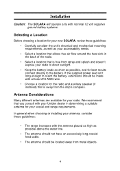
... choosing or installing your antenna, consider these guidelines: • Carefully consider the unit's electrical and mechanical mounting requirements, as well as possible, and for your radio. Installation Caution: The SOLARA will operate only with nominal 12 volt negative ground battery systems. Selecting a Location Before choosing a location for your new SOLARA, review these guidelines: • The range increases with the antenna placed as...
... choosing or installing your antenna, consider these guidelines: • Carefully consider the unit's electrical and mechanical mounting requirements, as well as possible, and for your radio. Installation Caution: The SOLARA will operate only with nominal 12 volt negative ground battery systems. Selecting a Location Before choosing a location for your new SOLARA, review these guidelines: • The range increases with the antenna placed as...
English Owners Manual
Page 9
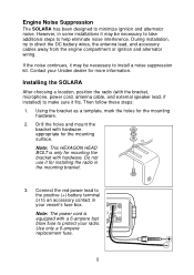
... suppression kit. Note: The power cord is only for mounting the bracket with hardware appropriate for installing the radio in the mounting bracket. 3. If the noise continues, it for the mounting surface. Connect the red power lead to the positive (+) battery terminal or to direct the DC battery wires, the antenna lead, and accessory cables away from the engine compartment or ignition and alternator wiring. Use only a 6-ampere replacement fuse. 5 Contact your Uniden...
... suppression kit. Note: The power cord is only for mounting the bracket with hardware appropriate for installing the radio in the mounting bracket. 3. If the noise continues, it for the mounting surface. Connect the red power lead to the positive (+) battery terminal or to direct the DC battery wires, the antenna lead, and accessory cables away from the engine compartment or ignition and alternator wiring. Use only a 6-ampere replacement fuse. 5 Contact your Uniden...

English Owners Manual
Page 10
Do not insert the screw without attaching the bracket. 6 4. Note: Do not use any other mounting knobs than the ones enclosed. Install the radio in the mounting bracket and connect the antenna cable and accessories to a ground source in your vessel's fuse box. 5. Connect the black wire of the power cord to the negative (-) battery terminal or to their appropriate jacks and connectors.
Do not insert the screw without attaching the bracket. 6 4. Note: Do not use any other mounting knobs than the ones enclosed. Install the radio in the mounting bracket and connect the antenna cable and accessories to a ground source in your vessel's fuse box. 5. Connect the black wire of the power cord to the negative (-) battery terminal or to their appropriate jacks and connectors.
English Owners Manual
Page 11
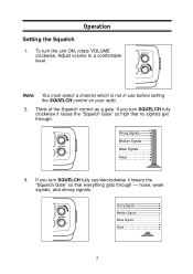
noise, weak signals, and strong signals. 7 Think of the Squelch control as a gate. Adjust volume to a comfortable level. If you turn the unit ON, rotate VOLUME clockwise. Note: You must select a channel which is not in use before setting the SQUELCH control on your radio. 2. Operation Setting the Squelch 1. If you turn SQUELCH fully counterclockwise it raises the "Squelch Gate" so high that everything gets through . 3. To turn SQUELCH fully clockwise it lowers the "Squelch Gate" so that no signals get through -
noise, weak signals, and strong signals. 7 Think of the Squelch control as a gate. Adjust volume to a comfortable level. If you turn the unit ON, rotate VOLUME clockwise. Note: You must select a channel which is not in use before setting the SQUELCH control on your radio. 2. Operation Setting the Squelch 1. If you turn SQUELCH fully counterclockwise it raises the "Squelch Gate" so high that everything gets through . 3. To turn SQUELCH fully clockwise it lowers the "Squelch Gate" so that no signals get through -
English Owners Manual
Page 12
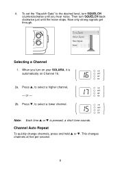
Then turn SQUELCH back clockwise just until you turn SQUELCH counterclockwise until the noise stops. When you hear noise. Press L, to select a lower channel. Note: Each time L or M is automatically on Channel 16. 2a. Now only strong signals get through. This changes channels at five per second. 8 or - 2b. Channel Auto Repeat To quickly change channels, press and hold L or M. Press M, to select a higher channel, - To set the "Squelch Gate" to the desired level, turn on your SOLARA, it is pressed, a short tone sounds. 4. Selecting a Channel 1.
Then turn SQUELCH back clockwise just until you turn SQUELCH counterclockwise until the noise stops. When you hear noise. Press L, to select a lower channel. Note: Each time L or M is automatically on Channel 16. 2a. Now only strong signals get through. This changes channels at five per second. 8 or - 2b. Channel Auto Repeat To quickly change channels, press and hold L or M. Press M, to select a higher channel, - To set the "Squelch Gate" to the desired level, turn on your SOLARA, it is pressed, a short tone sounds. 4. Selecting a Channel 1.
English Owners Manual
Page 13
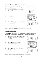
... CH16 again, to return to another channel using the CH16 button. 1. Note: Each time INT is pressed a short tone sounds. To change to the international frequencies. 3. Press INT, to the USA frequencies. Instant Channel 16 Communications You can transmit and receive both USA and International frequencies. Press INT again, to return to change the selected set of frequencies use INT. 1. When you are on , the...
... CH16 again, to return to another channel using the CH16 button. 1. Note: Each time INT is pressed a short tone sounds. To change to the international frequencies. 3. Press INT, to the USA frequencies. Instant Channel 16 Communications You can transmit and receive both USA and International frequencies. Press INT again, to return to change the selected set of frequencies use INT. 1. When you are on , the...
English Owners Manual
Page 14
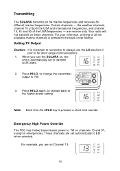
... sounds. Press HI/LO again, to change the transmitter output to 1W. 3. are set to 1W on Channel 13. 10 For your reference, a listing of the USA frequencies - Emergency High Power Override The FCC has limited transmission power to transmit at 25 watts. 2. For example, you turn the SOLARA on 54 marine frequencies and receives 80 different marine frequencies. These channels are receive only. Press HI/LO, to change...
... sounds. Press HI/LO again, to change the transmitter output to 1W. 3. are set to 1W on Channel 13. 10 For your reference, a listing of the USA frequencies - Emergency High Power Override The FCC has limited transmission power to transmit at 25 watts. 2. For example, you turn the SOLARA on 54 marine frequencies and receives 80 different marine frequencies. These channels are receive only. Press HI/LO, to change...
English Owners Manual
Page 15
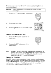
... flash, and the unit will not be used accordingly. 1. communication frequencies will not transmit. If necessary, you can override the LO power output setting during an emergency situation. Transmitting with the SOLARA 1. Transmitter Time-Out If the PTT button on your microphone is an emergency procedure and should be jammed. 11 Warning: This is held down and the power is turned on your receiver...
... flash, and the unit will not be used accordingly. 1. communication frequencies will not transmit. If necessary, you can override the LO power output setting during an emergency situation. Transmitting with the SOLARA 1. Transmitter Time-Out If the PTT button on your microphone is an emergency procedure and should be jammed. 11 Warning: This is held down and the power is turned on your receiver...
English Owners Manual
Page 16
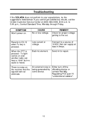
... key is noise on the receiver that Mfg. contact that the squelch will not eliminate. Reverts to the set. There is pressed. If you cannot get satisfactory results, call the Uniden Customer Service Center at least 4 Amps. to your expectations, try the suggestions listed below. An external noise is pressed - REMEDY Check for repair. When the PTT is Either turn...
... key is noise on the receiver that Mfg. contact that the squelch will not eliminate. Reverts to the set. There is pressed. If you cannot get satisfactory results, call the Uniden Customer Service Center at least 4 Amps. to your expectations, try the suggestions listed below. An external noise is pressed - REMEDY Check for repair. When the PTT is Either turn...
English Owners Manual
Page 17
...Owner's Manual Other Printed Material Microphone Hanger and Screws Mounting Bracket and Knobs 3.5mm Mini Plug and Spare Fuse 13 Replacement Parts These replacement parts are responsible for the continued FCC technical compliance of an emergency. Its rugged design requires very little maintenance; A defective antenna may cause damage to your radio...fresh water. • If the antenna has been damaged, you should not transmit except in the case of your radio, we recommend that you arrange for periodic performance checks with your Uniden Marine Dealer. however, these precautions should be...
...Owner's Manual Other Printed Material Microphone Hanger and Screws Mounting Bracket and Knobs 3.5mm Mini Plug and Spare Fuse 13 Replacement Parts These replacement parts are responsible for the continued FCC technical compliance of an emergency. Its rugged design requires very little maintenance; A defective antenna may cause damage to your radio...fresh water. • If the antenna has been damaged, you should not transmit except in the case of your radio, we recommend that you arrange for periodic performance checks with your Uniden Marine Dealer. however, these precautions should be...
English Owners Manual
Page 18
..., Monday through Friday 14 If you with complete service information. If you require service that will be able to assist you want factory service, please pack your radio in a suitable container that is within the terms of your warranty you contact the Uniden dealer where your purchase was made. Service Should you find it desirable or necessary to...
..., Monday through Friday 14 If you with complete service information. If you require service that will be able to assist you want factory service, please pack your radio in a suitable container that is within the terms of your warranty you contact the Uniden dealer where your purchase was made. Service Should you find it desirable or necessary to...

English Owners Manual
Page 19
Specification General Channels Controls Status Indicators Channel Display Channel Selector Buttons Connectors Size Weight Supply Voltage Antenna Impedance Microphone Speaker Operating Temperature Range Shock and Vibration FCC Approvals Transmitter Power Output Power Requirement Modulation Signal-to-Noise Audio Distortion Spurious Suppression Output Power Stabilization Frequency Range Frequency Stability: Receiver Frequency Range Sensitivity Circuit Squelch Sensitivity Spurious Response Adjacent Channel Selectivity Audio Output Power Power Requirement IF Frequencies Transmit 54 Receive 80 ...
Specification General Channels Controls Status Indicators Channel Display Channel Selector Buttons Connectors Size Weight Supply Voltage Antenna Impedance Microphone Speaker Operating Temperature Range Shock and Vibration FCC Approvals Transmitter Power Output Power Requirement Modulation Signal-to-Noise Audio Distortion Spurious Suppression Output Power Stabilization Frequency Range Frequency Stability: Receiver Frequency Range Sensitivity Circuit Squelch Sensitivity Spurious Response Adjacent Channel Selectivity Audio Output Power Power Requirement IF Frequencies Transmit 54 Receive 80 ...
English Owners Manual
Page 20
... retail sale. The Product should be of no further effect 36 months after following the instructions in this Operating Guide you are certain that has caused you without charge for parts, service, or any other than an authorized Uniden service center for this warranty, (E) used as part of any conversion kits, subassemblies, or any time while this warranty at : Uniden America Corporation Parts and Service...
... retail sale. The Product should be of no further effect 36 months after following the instructions in this Operating Guide you are certain that has caused you without charge for parts, service, or any other than an authorized Uniden service center for this warranty, (E) used as part of any conversion kits, subassemblies, or any time while this warranty at : Uniden America Corporation Parts and Service...
English Owners Manual
Page 21
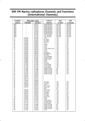
Weather VTS Port Ops Port Ops Port Ops VTS Safety Com'l Com'l Com'l & Non Com'l Com'l Com'l Port Ops Navigational Port Ops Environmental Safety Calling State Control Com'l Com'l Port Ops Coast... Yes Yes Yes Yes Yes Yes Yes Yes Yes No Weather Can. VHF FM Marine radiophone Channels and Functions (International Channels) CHANNEL DESIGN WXO WX1 WX2 WX3 WX4 WX5 WX6 WX7 WX8 ...73 74 77 78 79 80 81 82 83 84 85 86 87 88 FREQUENCY (MHz) TRANSMIT 156.050 156.100 156.150 156.200 156.250 ....125 157.175 157.225 157.275 157.325 157.375 157.425 RECEIVE 163.275 162.550 162.400 162.475 162.425 162.450 162....
Weather VTS Port Ops Port Ops Port Ops VTS Safety Com'l Com'l Com'l & Non Com'l Com'l Com'l Port Ops Navigational Port Ops Environmental Safety Calling State Control Com'l Com'l Port Ops Coast... Yes Yes Yes Yes Yes Yes Yes Yes Yes No Weather Can. VHF FM Marine radiophone Channels and Functions (International Channels) CHANNEL DESIGN WXO WX1 WX2 WX3 WX4 WX5 WX6 WX7 WX8 ...73 74 77 78 79 80 81 82 83 84 85 86 87 88 FREQUENCY (MHz) TRANSMIT 156.050 156.100 156.150 156.200 156.250 ....125 157.175 157.225 157.275 157.325 157.375 157.425 RECEIVE 163.275 162.550 162.400 162.475 162.425 162.450 162....
English Owners Manual
Page 22
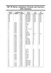
Weather VTS Port Ops Port Ops Port Ops VTS Safety Com'l Com'l Com'l & Non Com'l Com'l Com'l Port Ops Navigational Port Ops Environmental Safety Calling State Control Com'l Com'l Port Ops Coast Guard Coast Guard Coast Guard Public Corresp Public Corresp...Yes No Yes Yes No Yes Yes Yes No Yes No Yes Yes Yes Yes No VHF FM Marine radiophone Channels and Functions (USA Channels) CHANNEL DESIGN WX0 WX1 WX2 WX3 WX4 WX5 WX6 WX7 WX8 WX9 01 02 03 04 ...70 71 72 73 74 77 78 79 80 81 82 83 84 85 86 87 88 FREQUENCY (MHz) TRANSMIT RECEIVE 156.050 156.100 156.150 156.200 156.250 156.300 156.350 156.400 156...
Weather VTS Port Ops Port Ops Port Ops VTS Safety Com'l Com'l Com'l & Non Com'l Com'l Com'l Port Ops Navigational Port Ops Environmental Safety Calling State Control Com'l Com'l Port Ops Coast Guard Coast Guard Coast Guard Public Corresp Public Corresp...Yes No Yes Yes No Yes Yes Yes No Yes No Yes Yes Yes Yes No VHF FM Marine radiophone Channels and Functions (USA Channels) CHANNEL DESIGN WX0 WX1 WX2 WX3 WX4 WX5 WX6 WX7 WX8 WX9 01 02 03 04 ...70 71 72 73 74 77 78 79 80 81 82 83 84 85 86 87 88 FREQUENCY (MHz) TRANSMIT RECEIVE 156.050 156.100 156.150 156.200 156.250 156.300 156.350 156.400 156...


