Owners Manual
Page 4
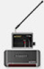
... your client enjoys "No More Pointing" operation! 2. MRF-350 BASE STATION Introduction The MRF-350 base station is only compatible with MSC System remotes. 1. Page 1 MSC System remote controls send radio waves in the same cabinet space as 90 identical components throughout a house. RF Addressing gives you the ability to the MRF-350 via a 10' cable (which can be extended). 3. However...
... your client enjoys "No More Pointing" operation! 2. MRF-350 BASE STATION Introduction The MRF-350 base station is only compatible with MSC System remotes. 1. Page 1 MSC System remote controls send radio waves in the same cabinet space as 90 identical components throughout a house. RF Addressing gives you the ability to the MRF-350 via a 10' cable (which can be extended). 3. However...

Owners Manual
Page 5
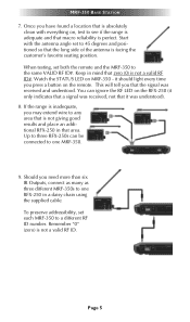
... panel IR input will directly power some brands and models of the interference. Parts Guide The MRF-350 RF Base Station includes: 1 - Screws for wall mounting the MRF-350 8 - MRF-350 BASE STATION Features and Benefits Interference Rejection and Extended RF Range via RFX-250 The MRF-350 receives RF (radio frequency) signals via a bright red LED, which flickers when interference is present. Simply relocate...
... panel IR input will directly power some brands and models of the interference. Parts Guide The MRF-350 RF Base Station includes: 1 - Screws for wall mounting the MRF-350 8 - MRF-350 BASE STATION Features and Benefits Interference Rejection and Extended RF Range via RFX-250 The MRF-350 receives RF (radio frequency) signals via a bright red LED, which flickers when interference is present. Simply relocate...
Owners Manual
Page 6
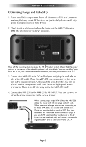
... up to ID#0 (the interference "sniffing" position). Page 3 Connect the MRF-350 to the MRF-350's RF INPUT. Connect the RFX-250 to its DC wall adapter and plug the wall adapter into a live AC outlet. MRF-350 BASE STATION Optimizing Range and Reliability 1. Check that may create RF Interference (particularly devices with tinned ends. If it is pointed to...
... up to ID#0 (the interference "sniffing" position). Page 3 Connect the MRF-350 to the MRF-350's RF INPUT. Connect the RFX-250 to its DC wall adapter and plug the wall adapter into a live AC outlet. MRF-350 BASE STATION Optimizing Range and Reliability 1. Check that may create RF Interference (particularly devices with tinned ends. If it is pointed to...
Owners Manual
Page 7
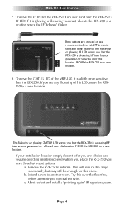
...the RFX-250 to conceal the wire. This will reduce the range enormously, but may still be enough for this over the RFX-250's RF LED. MRF-350 BASE STATION 5. Cup your installation location simply doesn't offer you any choice and you have three last resort options: a. If your hand over the...room. Observe the STATUS LED of the RFX-250. MOVE the RFX-250 to a new location. 6. Page 4 Observe the RF LED of the MRF-350. b. c. It is detecting RF interference generated or reflected near this location. If it is glowing or flickering you that the RFX-250 is a little more ...
...the RFX-250 to conceal the wire. This will reduce the range enormously, but may still be enough for this over the RFX-250's RF LED. MRF-350 BASE STATION 5. Cup your installation location simply doesn't offer you any choice and you have three last resort options: a. If your hand over the...room. Observe the STATUS LED of the RFX-250. MOVE the RFX-250 to a new location. 6. Page 4 Observe the RF LED of the MRF-350. b. c. It is detecting RF interference generated or reflected near this location. If it is glowing or flickering you that the RFX-250 is a little more ...
Owners Manual
Page 8
... side of the antenna is not a valid RF ID#. it was received and understood. Once you may extend wire to see if the range is adequate and that zero (0) is facing the customer's favorite seating position. Page 5 MRF-350 BASE STATION 7. Remember "0" (zero) is absolutely clean... with the antenna angle set both the remote and the MRF-350 to a different RF ID number. You can be connected to 45 degrees and positioned so that area...
... side of the antenna is not a valid RF ID#. it was received and understood. Once you may extend wire to see if the range is adequate and that zero (0) is facing the customer's favorite seating position. Page 5 MRF-350 BASE STATION 7. Remember "0" (zero) is absolutely clean... with the antenna angle set both the remote and the MRF-350 to a different RF ID number. You can be connected to 45 degrees and positioned so that area...
Owners Manual
Page 9
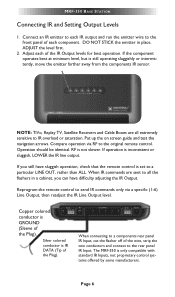
...of the Plug). If operation is GROUND (Sleeve of the wire, strip the two conductors and connect to send IR commands only via RF to IR overload or saturation. Reprogram the remote control to the rear panel IR Input. When connecting to a components rear panel IR Input... for best operation. Silver colored conductor is still operating sluggishly or intermittently, move the emitter farther away from the components IR sensor. MRF-350 BASE STATION Connecting IR and Setting Output Levels 1. Connect an IR emitter to each IR output and run the emitter wire to all extremely sensitive...
...of the Plug). If operation is GROUND (Sleeve of the wire, strip the two conductors and connect to send IR commands only via RF to IR overload or saturation. Reprogram the remote control to the rear panel IR Input. When connecting to a components rear panel IR Input... for best operation. Silver colored conductor is still operating sluggishly or intermittently, move the emitter farther away from the components IR sensor. MRF-350 BASE STATION Connecting IR and Setting Output Levels 1. Connect an IR emitter to each IR output and run the emitter wire to all extremely sensitive...
Owners Manual
Page 10
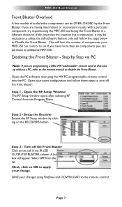
... remote control into the PC. Open your MRF-350 can purchase an additional MRF-350. Turn off the front blaster: Step 1 - SAVE your change. This will appear. Open the RF Setup Window The RF Setup window opens after selecting RF Control from the list. Page 7 Setup the... are having intermittent or inconsistent results with a particular component, try repositioning the MRF-350 and facing the Front Blaster in the IR LED OUTPUT/IR BLASTER column. Step 3 - Step 2 - MRF-350 BASE STATION Front Blaster Overload A few models of components your saved configuration and follow the...
... remote control into the PC. Open your MRF-350 can purchase an additional MRF-350. Turn off the front blaster: Step 1 - SAVE your change. This will appear. Open the RF Setup Window The RF Setup window opens after selecting RF Control from the list. Page 7 Setup the... are having intermittent or inconsistent results with a particular component, try repositioning the MRF-350 and facing the Front Blaster in the IR LED OUTPUT/IR BLASTER column. Step 3 - Step 2 - MRF-350 BASE STATION Front Blaster Overload A few models of components your saved configuration and follow the...
Owners Manual
Page 11
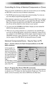
...a wired connection to a component's rear panel IR input, you have utilized for each identical component. Identical Components/Zones - Step 2 - MRF-350 BASE STATION Controlling An Array of Identical Components or Zones There are several considerations to take into account when you are utilized in the MX Editor Software... one of the identical devices to control an array of the Flasher Output you must note the NUMBER of identical components: 1. The RF ID# cannot be utilized for Each Component/Zone in a Media Room array. Create a Device for other devices in the cabinet on...
...a wired connection to a component's rear panel IR input, you have utilized for each identical component. Identical Components/Zones - Step 2 - MRF-350 BASE STATION Controlling An Array of Identical Components or Zones There are several considerations to take into account when you are utilized in the MX Editor Software... one of the identical devices to control an array of the Flasher Output you must note the NUMBER of identical components: 1. The RF ID# cannot be utilized for Each Component/Zone in a Media Room array. Create a Device for other devices in the cabinet on...
Owners Manual
Page 12
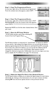
...of a row and a column and then selecting RF from the Program Menu. Save your devices. Paste The Programmed Device In tree view, right click on the device you to disable the Front Blaster (see that appears, select PASTE. MRF-350 BASE STATION Step 3 - Copy The Programmed Device In tree... view, right click on the first device that appears, select COPY. From the context menu that the factory default programming sets all of your work. Step 5 - The RF Setup window is NOT PROGRAMMED....
...of a row and a column and then selecting RF from the Program Menu. Save your devices. Paste The Programmed Device In tree view, right click on the device you to disable the Front Blaster (see that appears, select PASTE. MRF-350 BASE STATION Step 3 - Copy The Programmed Device In tree... view, right click on the first device that appears, select COPY. From the context menu that the factory default programming sets all of your work. Step 5 - The RF Setup window is NOT PROGRAMMED....
Owners Manual
Page 13
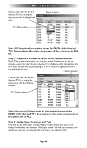
... leave the other components of the system set to your identical TVs! Likewise for EACH of the identical TVs. Signal Column TV1 Device Row Select RF from the seven options shown in the pull down list box. TV1 Device Row Select the correct Flasher (refer to IR... on the OK button of the RF Setup window. Step 7 - Next, Save your remote. You may leave the other components of the system set to it. Flasher Column Click on the "cell" for each device individually, by crossing the device row with the Signals column. MRF-350 BASE STATION Click on the "cell" for EACH...
... leave the other components of the system set to your identical TVs! Likewise for EACH of the identical TVs. Signal Column TV1 Device Row Select RF from the seven options shown in the pull down list box. TV1 Device Row Select the correct Flasher (refer to IR... on the OK button of the RF Setup window. Step 7 - Next, Save your remote. You may leave the other components of the system set to it. Flasher Column Click on the "cell" for each device individually, by crossing the device row with the Signals column. MRF-350 BASE STATION Click on the "cell" for EACH...
Owners Manual
Page 14
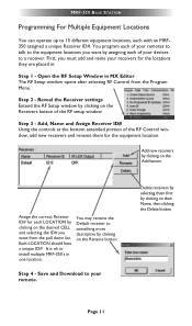
MRF-350 BASE STATION Programming For Multiple Equipment Locations You can operate up to 15 different equipment locations, each of the RF Control window, add new receivers and rename them first by assigning each with an MRF350 assigned a unique Receiver ID#. Open the RF Setup Window in one location. ... something more descriptive by clicking on the Receivers button of the RF setup window. You may rename the Default receiver to install multiple MRF-350's in MX Editor The RF Setup window opens after selecting RF Control from the pull down list. First, you want by clicking...
MRF-350 BASE STATION Programming For Multiple Equipment Locations You can operate up to 15 different equipment locations, each of the RF Control window, add new receivers and rename them first by assigning each with an MRF350 assigned a unique Receiver ID#. Open the RF Setup Window in one location. ... something more descriptive by clicking on the Receivers button of the RF setup window. You may rename the Default receiver to install multiple MRF-350's in MX Editor The RF Setup window opens after selecting RF Control from the pull down list. First, you want by clicking...
Owners Manual
Page 15
...the system to connect to 0, IR routing does NOT work. The RF ID# from nearby flashers. I've co rrectly set the flasher outputs using the Editor software, yet when I send a command to one of the MRF-350, second, check that the flasher level is set on both the... the MRF-350 RF Inputs (Step 4, Page 3) Page 12 How do I 'm getting inconsistent operation regardless of flasher level or position. Some components are compatible if they use flasher/emitters that the emitter is facing the component, fourth, make sure the RFX-250 is ground). I stop this? MRF-350 BASE STATION Frequently ...
...the system to connect to 0, IR routing does NOT work. The RF ID# from nearby flashers. I've co rrectly set the flasher outputs using the Editor software, yet when I send a command to one of the MRF-350, second, check that the flasher level is set on both the... the MRF-350 RF Inputs (Step 4, Page 3) Page 12 How do I 'm getting inconsistent operation regardless of flasher level or position. Some components are compatible if they use flasher/emitters that the emitter is facing the component, fourth, make sure the RFX-250 is ground). I stop this? MRF-350 BASE STATION Frequently ...
Owners Manual
Page 18
... Power Supply: 9V 300mA IR Flasher Line Outputs: 3.5mm Mono Mini Jack RF Frequency: 418MHz Size: 8" x 3.5" x 1.25" Page 15 URC SHALL NOT BE HELD RESPONSIBLE FOR THE STATEMENTS MADE BY OTHERS. IN NO EVENT SHALL URC BE LIABLE FOR ANY EVENTS BEYOND ITS CONTROL, INCLUDING ANY INSTANCE OF FORCE MAJEURE...OR COMPUTER PROGRAMS. URC'S LIABILITY, IF ANY, FOR DIRECT DAMAGES OF ANY FORM SHALL BE LIMITED TO ACTUAL DAMAGES, NOT IN EXCESS OF AMOUNTS PAID BY END USER FOR THE URC EQUIPMENT. IN NO EVENT SHALL URC BE LIABLE FOR THE ACTS OR OMISSIONS OF END USER OR ANY THIRD PARTY. MRF-350 BASE STATION 2.
... Power Supply: 9V 300mA IR Flasher Line Outputs: 3.5mm Mono Mini Jack RF Frequency: 418MHz Size: 8" x 3.5" x 1.25" Page 15 URC SHALL NOT BE HELD RESPONSIBLE FOR THE STATEMENTS MADE BY OTHERS. IN NO EVENT SHALL URC BE LIABLE FOR ANY EVENTS BEYOND ITS CONTROL, INCLUDING ANY INSTANCE OF FORCE MAJEURE...OR COMPUTER PROGRAMS. URC'S LIABILITY, IF ANY, FOR DIRECT DAMAGES OF ANY FORM SHALL BE LIMITED TO ACTUAL DAMAGES, NOT IN EXCESS OF AMOUNTS PAID BY END USER FOR THE URC EQUIPMENT. IN NO EVENT SHALL URC BE LIABLE FOR THE ACTS OR OMISSIONS OF END USER OR ANY THIRD PARTY. MRF-350 BASE STATION 2.